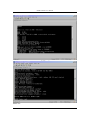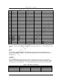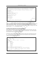
1
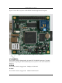
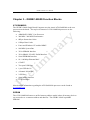
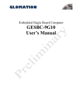
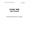
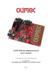
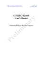
GESBC-9260S
User’s Manual
Embedded Single Board Computer
GESBC-9260S User’s Manual
Table of Contents
Chapter 1 – Introducing the GESBC-9260S Single Board Computer................................ 4
GESBC-9260S Overview ............................................................................................... 4
Advanced Features.......................................................................................................... 4
AT91SAM9260............................................................................................................... 5
SDRAM .......................................................................................................................... 5
FLASH............................................................................................................................ 5
USB................................................................................................................................. 6
UART.............................................................................................................................. 6
DEBUG Port ................................................................................................................... 6
Chapter 2 – Getting Started................................................................................................. 7
Assembly and Connections............................................................................................. 7
Operation......................................................................................................................... 7
Configurations................................................................................................................. 9
Chapter 3 – GESBC-9260S Function Blocks ................................................................... 10
AT91SAM9260............................................................................................................. 10
SDRAM ........................................................................................................................ 10
FLASH.......................................................................................................................... 11
USB............................................................................................................................... 11
RS-232 Port 0 and Port 1 .............................................................................................. 11
RS-485 .......................................................................................................................... 12
I2C Bus ......................................................................................................................... 12
Ethernet ......................................................................................................................... 12
USB Port ....................................................................................................................... 13
SPI Bus, On-chip A/D and GPIO ................................................................................. 13
RTC............................................................................................................................... 14
JTAG............................................................................................................................. 14
Power Requirement....................................................................................................... 15
Chapter 4 – Software Description..................................................................................... 16
Overview....................................................................................................................... 16
Data Storage on GESBC-9260S ................................................................................... 16
GESBC-9260S Linux Code .......................................................................................... 16
U-boot ........................................................................................................................... 16
U-boot Booting Linux................................................................................................... 16
Loading Linux Kernel and root File System................................................................. 17
Chapter 5 – Development Tools ....................................................................................... 19
Overview....................................................................................................................... 19
Linux Development Tool Chain ................................................................................... 19
Chapter 6 – Troubleshooting ............................................................................................ 21
Version 0.2
Page 2 of 21
8-Jan-09
GESBC-9260S User’s Manual
List of Tables
Table 1 System Configuration ............................................................................................ 9
Table 2 Debug UART Port 0 Connector.......................................................................... 11
Table 3 UART Port P1 Connector ................................................................................... 11
Table 4 RS-485 Port J6 .................................................................................................... 12
Table 5 J9 I2C bus ........................................................................................................... 12
Table 6 J16 I/O Expansion............................................................................................... 13
Table 7 J20 JTAG Connector ........................................................................................... 14
Table 8 J1 Power Supply Connector................................................................................. 15
Table 9 NAND FLASH Storage Map............................................................................... 16
Version 0.2
Page 3 of 21
8-Jan-09
GESBC-9260S User’s Manual
Chapter 1 – Introducing the GESBC-9260S Single Board
Computer
GESBC-9260S Overview
The GESBC-9260S is a low cost compact sized single board computer based on Atmel
AT91SAM9260 processor. With a large peripheral set targeted to a variety of
applications, the GESBC-9260S is well suited for industrial controls, digital media
servers, audio jukeboxes, thin clients, set-top boxes, point-of-sale terminals, biometric
security systems, and GPS devices.
Advanced Features
The heart of the GESBC-9260S is the AT91SAM9260 which is the one in a series of
ARM926EJ-S-based processors. The AT91SAM9260 microcontroller features DSP
Instruction Extensions, ARM Jazelle® Technology for Java® Acceleration. It has
separate 8 Kbyte instruction and data caches with write buffer. The ARM926EJ-S on the
AT91SAM9260 functions with a maximum operating clock rate of 200MHz and a power
usage between 20mW and 250mW (dependent upon clock speed). The ARM core
operates from a 1.8V supply while the I/O operates at 3.3V. The low power
consumption makes it an idea platform for battery operated applications. The GESBC9260S is wireless ready with ZigBee and USB WiFi interfaces.
The list below summarizes the features of the GESBC-9260S.
•
•
•
•
•
•
•
•
•
•
•
•
•
•
•
•
•
200MHz Processor Core – ARM926EJ-S with MMU
32 ~ 64MB SDRAM
128MB ~ 1GB NAND FLASH
4 channel 10-bit Analog-to-Digital Converter (ADC
2 RS-232 Universal Asynchronous Receiver / Transmitters (UARTs)
1 USB Host Port
1 USB Device Port
Real-Time Clock with battery backup
Hardware Debug Interface (JTAG)
SD/MMC Socket
GPIO Ports with high current drive (up to 16mA)
1 I2C Port
1 SPI Port
Optiona 10/100 Mbps Ethernet port
Optional RS-485 Port
ZigBee interface for optional ZigBee module.
USB WiFi connector for optional USB WiFi module
Version 0.2
Page 4 of 21
8-Jan-09
GESBC-9260S User’s Manual
Figure 1 below shows a picture of the GESBC-9260S Single Board Computer.
Figure 1. GESBC-9260S Single Board Computer
AT91SAM9260
The GESBC-9260S is shipped with the Atmel AT91SAM9260 processor. For more
information regarding the AT91SAM9260 processor please see the AT91SAM9260
datasheet.
SDRAM
The GESBC-9260S is shipped with 32MBytes of SDRAM.
FLASH
The GESBC-9260S is shipped with 128MB NAND FLASH.
Version 0.2
Page 5 of 21
8-Jan-09
GESBC-9260S User’s Manual
USB
The GESBC-9260S is shipped with 1 USB host port, and 1 USB device port.
UART
The GESBC-9260S is shipped with a RS-232 interface with hardware handshaking
signals.
DEBUG Port
The GESBC-9260S is shipped with the 3 wire RS-232 serial debug port.
Version 0.2
Page 6 of 21
8-Jan-09
GESBC-9260S User’s Manual
Chapter 2 – Getting Started
This chapter describes the GESBC-9260S working environment and familiarizes the user
with its components and functionality. This chapter contains the following sections:
•
Assembly and Connections
o Describes how to assemble and connect components to the GESBC-9260S
Single Board Computer
•
Operation
o Describes how to operate the GESBC-9260S Single Board Computer
Assembly and Connections
In order to use the GESBC-9260S the user must first assemble and connect the
peripherals to the GESBC-9260S, as described in the following procedure.
1. Place the GESBC-9260S on a static free surface.
2. Make sure all of the jumpers are in the factory default position. The unit is
shipped in a factory default configuration. If the user is uncertain that the
GESBC-9260S has the jumpers in the factory default configuration, please see the
next section regarding board configuration.
3. Connect 5V regulated power supply to the board.
4. Connect null modem serial cable between GESBC-9260S debug port P0 and
PC/terminal serial port.
5. Launch a terminal emulator, such as HyperTerminal, or minicom, on the PC
configured to connect to the serial port of the GESBC-9260S. Configure the
serial port with the following parameters: 115200 bits per second, 8 data bits, no
parity, 1 stop bit, no flow control.
Operation
A few seconds after applying power to the GESBC-9260S, debug information will be
displayed on the terminal program. The following figures show what this should look
like.
Version 0.2
Page 7 of 21
8-Jan-09
GESBC-9260S User’s Manual
Please see
Version 0.2
Page 8 of 21
8-Jan-09
GESBC-9260S User’s Manual
Chapter 4 – Software Description for more details regarding the software functionality.
Configurations
Jumpers are used to configure the GESBC-9260S to operate in different mode. The
following table lists all the settings for each jumper.
Jumper
S1
BP1
Version 0.2
Table 1 System Configuration
Description
PA6 port input for boot strap code boot mode
open – normal ROM boot sequence
close – ROM debug mode
System reset switch header
Page 9 of 21
8-Jan-09
GESBC-9260S User’s Manual
Chapter 3 – GESBC-9260S Function Blocks
AT91SAM9260
The GESBC-9260S Single Board Computer uses the Atmel AT91SAM9260 as the core
processor on the board. The top-level features of AT91SAM9260 processor are the
following:
•
ARM926EJ-S RISC Core Processor
•
200 MHz / 200 MIPS Performance
•
8Kbyte Instruction Cache
•
8 Kbyte Data Cache
•
Linux and Windows CE enabled MMU
•
100 MHz System Bus
•
32 bit SDRAM Interface
•
32 bit SRAM / FLASH / ROM Interface
•
Serial EEPROM Interface
•
10 / 100 Mbps Ethernet MAC
•
6 UART
•
Two-port USB Host
•
1 port USB device
•
4 channel 10 bit ADC
•
2 SPI Port
•
Serial Audio Interface
•
JTAG Interface
More detailed information regarding the AT91SAM9260 processor can be found at
www.atmel.com.
SDRAM
The AT91SAM9260 features a unified memory address model where all memory devices
are accessed over a common address and data bus. The GESBC-9260S up 64MB
SDRAM.
Version 0.2
Page 10 of 21
8-Jan-09
GESBC-9260S User’s Manual
FLASH
The GESBC-9260S is shipped with 128 Mbytes of NAND FLASH memory. The
GESBC-9260S can be also ordered with optional 256MB ~ 1GB NAND FLASH.
USB
The GESBC-9260S Single Board Computer provides two USB host connections. The
AT91SAM9260 USB host controller is configured for one root hub port and features an
integrated transceiver for the port. The AT91SAM9260 integrates one USB 2.0 Full
Speed host port. The port is fully compliant to the OHCI USB 2.0 Full Speed
specification (12 Mbps). The controller complies with the OHCI specification for USB
Revision 1.1. The USB port are brought out by a standard USB type A connector.
The GESBC-9260S Single Board Computer provides one USB device port. The USB
Device Port (UDP) is compliant with the Universal Serial Bus (USB) V2.0 full-speed
device specification.
RS-232 Port 0 and Port 1
The GESBC-9260S Single Board Computer is shipped with one 5 wire RS-232 UART
interface and one 3 wire RS-232 debug UART port.
The port 0 is the debug USART port of the AT91SAM9260. It is provided via a 3 pin
header. The signal designation is listed in the following table.
Table 2 Debug UART Port 0 Connector
Pin Number
Signal Name
1
RX
2
TX
3
GND
The port 1 is the USART 0 of the AT91SAM9260. It is provided via a standard DB9
male connector with hardware handshake signals.
Table 3 UART Port P1 Connector
Pin Number
Signal Name
1
NC
3
TX
5
GND
7
RTS
9
NC
Version 0.2
Pin Number
2
4
6
8
Page 11 of 21
Signal Name
RX
NC
NC
CTS
8-Jan-09
GESBC-9260S User’s Manual
RS-485
The GESBC-9260S Single Board Computer provides one optional full/half duplex RS485 port. The RS-485 port is connected to USART3 with RTS signal for RS-485 driver
direction control. The RS-485 signal is provided via a 1x5 2.54mm spacing header J6.
JP3 selects half or full duplex mode, connects pin 1 and 2 set the RS-485 driver to full
duplex mode and connects pin 2 and 3 set the RS-485 driver to half duplex mode.
Table 4 RS-485 Port J6
Pin Number
Signal Name
1
RXA
2
RXB
3
TXB
4
TXA
5
GND
The RTS3 is connected to the RS-485 driver chip for data direction control in half duplex
mode. The normal setting of RTS signal is normally low. For RS-485 mode the RTS
signal must set to normally high. The user program must set the RTS mode before the
half duplex mode RS-485 port can be used. When operating in half duplex mode the
TXA and TXB are internally connected to RXA and RXB.
I2C Bus
The GESBC-9260S Single Board Computer provides one I2C bus interface via a 1x3
2.54mm spacing header J9.
Table 5 J9 I2C bus
Pin Number
1
2
3
Signal Name
SDA
SCL
GND
Ethernet
The GESBC-9260S Single Board Computer has optional Ethernet interface. The
AT91SAM9260 contains a MAC subsystem that is compliant with the ISO/TEC 802.3
topology for a single shared medium with several stations. The Media Access Controller
(MAC) within the AT91SAM9260 supports 1/10/100 Mbps transfer rates and interfaces
to industry standard physical layer devices. The optional DM9161A 100Base-X /
10Base-T Transceiver device which, along with a RJ45 connector, provides the physical
layer interface.
Version 0.2
Page 12 of 21
8-Jan-09
GESBC-9260S User’s Manual
USB Port
The GESBC-9260S Single Board Computer is shipped with 1 USB host port on standard
USB type-A connector. The USB host port also is available from a 6 position 1mm
spacing mini connector that interfaces directly to Via VT6656 USB WiFi module.
The GESBC-9260S Single Board Computer is shipped with one USB device port on a
standard USB type B connector.
SPI Bus, On-chip A/D and GPIO
The AT91SAM9260 contains very rich set of peripherals that are multiplex into 2 groups,
Peripheral A and Peripheral B, with individually programmable pins. The SPI bus, A/D
and GPIO are provided together with other functions on the I/O expansion port. The I/O
expansion port is a 2x25 2.54mm spacing header. The following table lists signals
available on the I/O expansion connector with their corresponding multiplexed functions
and default usage on the GESBC-9260S Single Board Computer.
Table 6 J16 I/O Expansion
Pin I/O Line
Peripheral A
1
2
3
PB0
SPI1_MISO
4
PB1
SPI1_MOSI
5
PB2
SPI1_SPCK
6
PB3
SPI1_NPCS0
7
PB8
TXD2
8
PB9
RXD2
9
PB10
TXD3
10 PB11
RXD3
11 PB16
TK0
12 PB17
TF0
13 PB18
TD0
14 PB19
RD0
15 PB20
RK0
16 PB21
RF0
17 PB22
DSR0
18 PB23
DCD0
19 PB24
RTR0
20 PB25
RI0
21 PB30
PCK0
22 PB31
PCK1
23 PC0
AD0
24 PC1
AD1
25 PC4
A23
26 PC5
A24
Version 0.2
Peripheral B
Comments
Function
+3.3V
+3.3V
TIOA3
TIOB3
TIOA4
TIOA5
ISI_D8
ISI_D9
TCLK3
TCLK4
TIOB4
TIOB5
ISI_D0
ISI_D1
ISI_D2
ISI_D3
ISI_D4
ISI_D5
ISI_HSYNC
ISIMCK
SCK3
PCK0
SPI1_NPCS2
SPI1_NPCS1
Page 13 of 21
RS-485 Port
RS-485 Port
8-Jan-09
GESBC-9260S User’s Manual
27
28
29
30
31
32
33
34
35
36
37
38
39
40
41
42
43
44
45
46
47
48
49
50
PC6
PC7
PC8
PC9
PC10
PC11
PC16
PC17
PC18
PC19
PC20
PC21
PC22
PC23
PC24
PC25
PC26
PC27
PC28
PC29
PC30
PC31
TIOB2
TIOB3
NCS4/CFCS0
NCS5/CFCS1
A25/CFRNW
NCS2
D16
D17
D18
D19
D20
D21
D22
D23
D24
D25
D26
D27
D28
D29
D30
D31
CFCE1
CFCE2
RTS3
TIOB0
CTS3
SPI0-_NPCS1
SPI0-_NPCS2
SPI0-_NPCS3
SPI1-_NPCS1
SPI1-_NPCS2
SPI1-_NPCS3
EF100
TCLK5
RS-485
GND
GND
For more detailed information on multiplexed peripherals please see AT91SAM9260 data
sheet.
RTC
The GESBC-9260S uses the AT91SAM9260 on-chip RTC with battery hook-up to
provide accurate time keeping. The on-board battery holder accepts CR1220 coin cell
batteries.
JTAG
The GESBC-9260S Single Board Computer is shipped with a 10 pin connector that
provides JTAG debug signals for the CPU. The JTAG provides the user with the ability
to debug system level programs. The signal designation is listed in the following table.
Pin Number
1
3
5
Version 0.2
Table 7 J20 JTAG Connector
Signal Name
Pin Number
3.3V
2
NTRST
4
TMS
6
Page 14 of 21
Signal Name
3.3V
TDI
TCK
8-Jan-09
GESBC-9260S User’s Manual
7
9
RTCK
GND
8
10
TDO
GND
ZigBee Interface
The GESBC-9260S Single Board Computer is shipped with socket for XBeeZnet2.5
module from Digi. The serial data lines connected to the ZigBee interface are RXD1 and
TXD1 from the AT91SAM9260 processor. The hardware control signals are RTS1
(PB28) and CTS1 (PB29) from the AT91SAM9260 processor. The system reset signal
NRST is connected to the module RESET line pin 5.
Power Requirement
The GESBC-9260S Single Board Computer requires regulated 5V DC. The power
supply should have minimum 350mA capacity.
Table 8 J1 Power Supply Connector
Pin Number
Signal Name
1
5V DC
2
GND
Version 0.2
Page 15 of 21
8-Jan-09
GESBC-9260S User’s Manual
Chapter 4 – Software Description
Overview
This chapter provides information regarding the software that is shipped with the
GESBC-9260S Board. The software included with the board is U-boot boot loader,
Linux kernel 2.6.25, and Debian distribution style compact root file system. The
applications included provide access to all hardware functions on the GESBC-9260S
board.
Data Storage on GESBC-9260S
The default configuration of the GESBC-9260S Single Board Computer uses on board
NAND FLASH for all data storage requirements, including boot strap code, boot loader,
Linux kernel, and Linux file system.
The following table is the storage map on the NAND FLASH.
Table 9 NAND FLASH Storage Map
Start Address
Size
Usage
0x00000000
0x20000
Boot strap code
0x00020000
0x40000
U-boot
0x00060000
0x40000
U-boot primary environment storage range
0x000A0000
0x40000
U-boot secondary environment storage range
0x00100000
0x300000
Linux kernel
0x00400000
-Root file system
GESBC-9260S Linux Code
The GESBC-9260S is shipped with Linux 2.6.25 kernel pre-installed. This software is
programmed into the system FLASH located on the board prior to shipment. The Linux
kernel is configured with all the device drivers included for the GESBC-9260S board.
U-boot
U-boot provides a simple interface for loading operating systems and applications onto
the GESBC-9260S board. U-Boot uses a serial console for its input and output. The
default serial port setting is 115200,8,N,1. It also supports the built-in Ethernet port and
general flash programming.
The board is shipped with U-boot pre-installed. Please refer to U-boot user’s manual
regarding detailed information of U-boot.
U-boot Booting Linux
The following shows the default U-boot setup for booting Linux.
Version 0.2
Page 16 of 21
8-Jan-09
GESBC-9260S User’s Manual
U-Boot> printenv
bootargs=console=ttyS0,115200 root=/dev/mtdblock2 rw rootfstype
=jffs2 mtdparts=at91_nand:1M(bootloader),3M(kernel),-(rootfs)
bootcmd=nand read.jffs2 0x21800000 0x100000 0x200000; bootm
0x21800000
bootdelay=1
baudrate=115200
ethaddr=00:0c:20:02:0a:5b
ipaddr=192.168.0.200
serverip=192.168.0.102
netmask=255.255.255.0
stdin=serial
stdout=serial
stderr=serial
ethact=macb0
Environment size: 353/131067 bytes
U-Boot>
The bootcmd setting of the U-boot reads the Linux kernel from NAND FLASH at
address 0x100000 to SDRAM at address 0x21800000 and start executing the kernel code
at the same memory address. The NAND FLASH from 0x400000 and up is used for
Linux root file system. The U-boot passes the MTD device partition setting to the Linux
kernel via the bootargs environment variable.
Loading Linux Kernel and root File System
The U-boot boot-loader provides many ways to load Linux kernel and file system into
FLASH memory. The loading by Ethernet network is shown here. User can consult Uboot manual for other methods of loading data.
After power on the GESBC-9260S board, stop the U-boot auto-execution by press any
key. The following message should be shown on the terminal console on the host PC
connected to the GESBC-9260S board.
RomBOOT
>
U-Boot 1.3.3 (Jul 19 2008 - 15:50:33)
DRAM: 34 MB
NAND: 128 MiB
In:
serial
Out:
serial
Err:
serial
Net:
macb0
macb0: Starting autonegotiation...
macb0: Autonegotiation timed out (status=0x7849)
macb0: link up, 100Mbps full-duplex (lpa: 0x4de1)
Hit any key to stop autoboot: 0
U-Boot>
Version 0.2
Page 17 of 21
8-Jan-09
GESBC-9260S User’s Manual
The net work address and server address must be set before network transfer can take
place. The following commands will set the SBC IP address and server IP address,
set ipaddr xxx.xxx.xxx.xxx
set serverip xxx.xxx.xxx.xxx
The server IP is the IP address where a TFTP server must be run. To load Linux kernel
type in the following command,
t 0x21800000 uImage
The U-boot will load uImage file from the TFTP server whose IP address is specified by
the serverip environment vairbale.
The NAND FLASH sectors must be erased first before new kernel image can be stored.
The following command will erase the NAND FLASH sectors reserved for Linux kernel,
nand erase 0x100000 0x200000
The use the flowing command to store the kernel image from SDRAM to NAND FLASH,
nand write.jffs2 0x21800000 0x100000 0x200000
The following commands can be used to load root file system into the FLASH memory,
nand erase 0x400000 [available_nand_flash_memory_size]
t 0x21000000 rootfs.img
nand write.jffs2 0x21000000 x0400000 $(filesize)
Please be noted that the image is first loaded into the SDRAM and then stored into the
FLASH memory. The image size can not exceed the available SDRAM on the board.
After the kernel and root file system have been updated the board can be simply reboot
by recycle the power.
Version 0.2
Page 18 of 21
8-Jan-09
GESBC-9260S User’s Manual
Chapter 5 – Development Tools
Overview
This chapter provides a brief introduction to development tools that are available for the
AT91SAM9260 System-on-a-Chip processor. The central processing core on the
AT91SAM9260 is a 200 MHz ARM926EJ-S processor. The ARM926EJ-S RISC
processing core is supported through various toolsets available from third party suppliers.
The typical toolset required for the code development is a compiler, assembler, linker and
a source-level code debugger. Code debugging is supported via the on-chip JTAG
interface.
Linux Development Tool Chain
The Linux development tool chain is available at Glomation website in the support page.
A host PC running Linux operating system is required to run the development tools. This
guide assumes user had basic Linux or Unix application development knowledge.
Host Computer Requirement
The host PC should run Redhead, SuSe, or other Linux distribution, a RS-232 serial port,
at least 500MB free disk space, and a terminal program such as minicom.
Hardware Connection
A null modem cable is required to connect GESBC-9260S to the host computer.
Install Linux Development Tool Chain
The ARM Linux Development Tool chain can be installed in any directory on the host
system. The following example uses cross compiler default directory /usr/local/arm as
the installing directory for the ARM Linux cross compiler.
1. Login as root and untar the tool chain
cd /
tar jxvf /<cross compiler tar file directory>/ Generic-arm_gcc4.2.3-glibc-2.3.3.tar.bz2
2. Set up the directory path variable
export PATH=/usr/local/arm/gcc-4.2.3-glibc-2.3.3/arm-unknownlinux-gnu/bin:$PATH
Version 0.2
Page 19 of 21
8-Jan-09
GESBC-9260S User’s Manual
above command can be included in the shell resource file so it is executed every
time you login. For bash shell, a good place to put is in .bashrc in your home
directory.
Compile Linux Kernel
The GESBC-9260S is shipped with Linux kernel version 2.6.25. The patch for the
kernel source tree is available at Glomation website in the support page.
Prepare Linux Kernel source
Obtain the kernel source 2.6.25 from http://www.kernel.org. Untar the Linux kernel,
tar xjf
linue-2.6.25.bz2
Patch the kernel source with GESBC-9260S patch,
patch –p1 < /<patch-file-directory-path>/patch_file_name
Configure Linux Kernel
The GESBC-9260S can use the default configuration file for the Atmel AT91SAM9260ek evaluation board.
make ARCH=arm CROSS_COMPILE=arm-unknown-linux-gnuat91sam9260ek_defconfig
If additional configuration is required, executing the following command in the Linux
kernel directory,
make ARCH=arm CROSS_COMPILE=arm-unknown-linux-gnu- menuconfig
If problem occurs, make sure the default PATH variable is set to the correct tool chain
directory
Compile Kernel
Once Linux kernel has been configured, it can be compiled using following command,
make ARCH=arm CROSS_COMPILE=arm-unknown-linux-gnu- uImage
The Linux kernel should compile without error and the image file will be created.
Version 0.2
Page 20 of 21
8-Jan-09
GESBC-9260S User’s Manual
Chapter 6 – Troubleshooting
This chapter provides Troubleshooting information. Search the entries in the Problem
column in order to find the item that best describes your situation. Then perform the
corrective action in the same row. If the problem persists, contact Glomation.
Version 0.2
Page 21 of 21
8-Jan-09