1
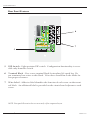
TM
Programmable Flush-Mount Control Panel
Designer’s Manual
GENERAL CAUTIONS AND WARNINGS!
To prevent electrical shock or potential fire hazards, do not expose XControl™ products to moisture or rain.
Before using this product, read the user manual for further warnings and cautions.
The following cautions should be carefully observed when installing, wiring, servicing or using
this product:
DO NOT remove the face plate/panel assembly of the unit. There are no user serviceable parts on the circuit assembly. Refer service to qualified personnel.
DO NOT use solvents or other cleaners to clean the unit. Basic external care
requires only a damp cloth. Disconnect the power supply cabling before cleaning.
Read all safety and installation instructions and retain all documentation for further
reference.
The XControl 4L should be installed so that its mounting position does not interfere with proper ventilation.
This product should not be installed or placed near a source of heat.
Power supply cabling and associated connectors should be unplugged from the
power source when the unit is not used for long periods of time, or will be stored.
This product requires mounting in NEMA metal enclosures. Mounting this product
in open space, or in plastic enclosures is not recommended.
Care should be taken to ensure that the installation is clear of possible sources of
contamination. Make sure that the product’s ventilation openings are not exposed
to possible sources of liquid, gases, or other contaminant.
This product should be inspected by a qualified service technician if the power supply cabling or connectors have been damaged, if the unit has been dropped, or if a
foreign substance has gained access to the interior electronic and electrical components.
The information contained in this manual is subject to change without notice. Peavey Electronics
is not liable for improper installation or configuration. The information contained herein is
intended only as an aid to qualified personnel in the design, installation and maintenance of engineered audio systems. The installing contractor or end user is ultimately responsible for the successful implementation of these systems.
All creative content in this manual, including the layout, art design, content, photography, drawings, specifications and all other intellectual property is Copyright ® 2002 Peavey Electronics
Corporation. All Rights Reserved.
Manual by WR.
Table Of Contents
1- Welcome.........................................................................................................................................5
Thank You!..................................................................................................................................................6
What’s in the box?....................................................................................................................................7
Other XControl™ products.....................................................................................................................7
Features.......................................................................................................................................................8
Applications................................................................................................................................................9
2-Fundamentals...............................................................................................................................11
Design Considerations...........................................................................................................................12
Infrastructure............................................................................................................................................13
Using XControl........................................................................................................................................14
Front Panel Features...............................................................................................................................16
Rear Panel Features.................................................................................................................................17
3- Installation..........................................................................................................................................19
Mechanical................................................................................................................................................20
Cabling & Connections........................................................................................................................20
Data Network Wiring............................................................................................................................21
Connection Summary.............................................................................................................................23
4- Configuration....................................................................................................................................25
Configuration Overview.......................................................................................................................26
Base Address Basics................................... ............................................................................................27
5- Appendix.....................................................................................................................................29
Control Sequence Number Chart.......................................................................................................30
Frequently Asked Questions................................................................................................................34
Serial Command Strings........................................................................................................................35
1
Welcome
XControl™ 4L Designer’s Manual
Thank You!
Thank you for adding XControl panels to your
MediaMatrix® system. The XControl flush
mounted control panels are designed from the
ground up, specifically for the integrated systems contractor. In spite of the vast array of
external control options available for
MediaMatrix systems, XControl adds yet
another dimension to end user interface.
You will find the combination of XControl panels and MediaMatrix software to be an
extremely powerful way for you to provide the
end-user an intuitive, flexible and cost-effective
control interface.
While the XControl panels include intelligent
functionality and software controlled features,
the real power of XControl the external control
functionality built into the MediaMatrix software environments, both MWare™ and XWare™.
Using some forethought, planning and good
basic design will allow the system integrator to
maximize system functionality while keeping
costs down, maintaining high usability.
Page 6
http://mediamatrix.peavey.com copyright 2002 All Rights Reserved
Welcome
What’s in the box?
XControl™ panels are packaged in a single container and include the following items:
•
XControl 4L flush-mount panel
Black Phillips head countersunk 6-32 mounting screws (2)
•
•
#6 Insulated Spade Lugs (5)
•
120 ohm terminating resistors (2)
•
User manual (this manual)
If any of these items are missing, please contact
the MediaMatrix® Tech Support department.
Other XControl products
In addition to the 4L, the current XControl line
includes two other panels that will make your
system even more flexible. Call your sales rep,
or the MediaMatrix sales department for more
information on all of the exciting XControl
products.
•
4x4
The 4x4 is a 2-gang NEMA panel with 4 programmable buttons and 4 programmable “virtual” rotary controls. All controls include status
LEDs.
•
4S
The 4S is a 1-gang NEMA panel with 4 programmable buttons and status LEDS.
All XControl products operate on the same network. Using a combination of panels will give
your system complete efficiency and maximum
ease of use.
MediaMatrix® - A Division Of Peavey Electronics Corp.
Page 7
XControl™ 4L Designer’s Manual
Features
1-gang NEMA mount
4 assignable rotary controls
• LED control status indicators
• Label space for customization
™
• Up to 8 XControls on a single X-Frame 88,
®
32 on frame-based MediaMatrix systems
• RS-485 network connectivity
• Easy wiring & installation
• Configurable controls
• Application examples available
• Attractive cosmetic package
• Standard 1G mounting
• Flexible
• Addressable
• Tracking rotary controls for multiple locations
• Software upgradeable
• Bus or local power supply options
• Low power requirements
• Cost effective
•
•
Page 8
http://mediamatrix.peavey.com copyright 2002 All Rights Reserved
Welcome
Applications
XControl™ flush mounted controllers are
designed for applications where simple enduser control is required. Intended for easy
access to fundamental system parameters,
XControl products are especially useful in
applications where system technicians, as well
as users, need access to specific system controls.
Among the many applications where XControl
provides fundamental benefits are:
Conference Rooms
Meeting Rooms
Combinable Ballrooms
Paging Systems
Entertainment Systems
Theatre BOH (Back of House)
Bars & Restaurants
Schools
Medical Facilities
Institutional Facilities
Municipal Facilities
Courtrooms
Lecture Halls
Presentation Rooms
Of course, many other applications are suitable
for XControl products. Because XControl
products are configurable, there is practically
no limit to the number of applications where
XControl can be implemented. From simple
volume controls to pre-recorded message playback, XControl provides rich functionality for
any application. Use your imagination, and
install XControl for all of your system installations.
MediaMatrix® - A Division Of Peavey Electronics Corp.
Page 9
2
Fundamentals
XControl™ 4L Designer’s Manual
Design Considerations
XControl flush mounted controllers include an
open-architecture design. Each virtual knob on
the 4L is configurable within the XWare™ or
MWare™ software. XControl panels provide
rich programmable functionality that allow the
system designer complete control over all system parameters, end user access and system
maintenance.
It is important to understand that out of the
box, XControl panels will do nothing. Each
control must be configured within the
MediaMatrix® software. Sample configuration
files are available for use with the X-Frame™ 88
which provide a good starting point for the system designer. With regular MediaMatrix,
XControl is completely configurable, using
MWare's powerful ControlGroup functionality.
There are no assumptions as to the intended
use, since the sky is pretty much the limit when
using XControl with MediaMatrix systems.
XControl adds a new level of end-user interface
to your system. No longer are you limited to
on-screen interface, CV controls or third-party
control systems. XControl can be used as a
stand-alone controller or in conjunction with
any of these other control options.
When using XControl panels, it is much easier
to integrate their functionality into your system
at the design level. Especially with frame-based
MediaMatrix systems, XControl integration
should be planned for at the earliest possible
phase of your system design.
Page 12
http://mediamatrix.peavey.com copyright 2002 All Rights Reserved
Fundamentals
Infrastructure
Like all integrated system work, infrastructure
is among the most important design factors.
With XControl™, infrastructure is equally
important, and must be designed and installed
correctly in order to provide reliable and errorfree performance.
Each XControl panel in your system requires
two separate connections. Both connections
are terminated to the rear panel 5-screw terminal block. (See the wiring details in this manual for more information on terminations.)
POWER
Each XControl panel requires power. Power
can be supplied from an AC or DC supply and
installed locally or on a bus architecture.
Depending on the number of XControl panels
in your system, available conduits and equipment closets, etc., you may require a centrally
located power supply. If this is the case, the
power supply should be capable of providing
enough current at the operating voltage for the
entire string of panels in the system. In some
systems, using local "wall wart" power supplies
may be a better solution.
NETWORK
XControl panels use a form of RS-485 (X-Net™)
to communicate to the MediaMatrix® processor.
This network provides connectivity for up to 8
XControl panels on a single X-Frame™ 88
processor, and 32 panels for regular frame-based
MediaMatrix systems.
The network connection is a "bus" architecture.
The easiest way to implement XControl panels
is to "daisy chain" the panels on a single wiring
bus that connects across all panels in the sys-
MediaMatrix® - A Division Of Peavey Electronics Corp.
Page 13
XControl™ 4L Designer’s Manual
tem. A single RS-485 connection then terminates to the MediaMatrix® system. If a bus
architecture is not possible due to the facility's
conduit or wireway limitations, separate home
runs between the XControl panels and the
MediaMatrix system may be required. In this
case, all home runs of RS-485 cable from
XControl panels should be terminated to a single network connection at the MediaMatrix
system. In systems where a large number of
home runs are necessary, a separate terminal
block may be required to allow better management of the multiple terminations. Refer to the
connections section for details.
Using XControl
One of the primary uses for XControl panels is
to provide simple, intuitive access of system
parameters to end-users. As a result of openarchitecture and configurable design of the
MWare™ software, XControl panels can be
implemented to provide just about any function
that an end user may require.
Each XControl panel includes label space so
that you can identify the function of each button, knob or LED on the XControl panel. This
identification is critical to the successful implementation of systems using XControl. The
label space provides enough room for any type
of label, including custom labels made from
engraved plastic or embossed aluminum products. For less critical environments, labels
could be generated from handheld label making
systems.
While a label will identify specific control use,
the XControl's LEDs will provide visual feedback on function status. LEDs on XControl
panels provide different status feedback,
depending on the color of the LED.
Page 14
http://mediamatrix.peavey.com copyright 2002 All Rights Reserved
Fundamentals
RED
Red LEDs indicate the status of a variable control, typically an audio function. All XControl™
rotary controls include red LED arrays to indicate a variable system parameter change.
GREEN
Green LEDs indicate function. For example,
XControl rotary controls can be changed by
pushing on the knob. Each push of the knob
will change the function of the knob. An illuminated green LED will indicate each subsequent function of the knob. A label space adjacent to the green LED makes it easy to identify
each function or use.
In addition, XControl panels with buttons use
green LEDs to indicate feedback tied to button
function.
(Buttons and associated LEDs not included on
the 4L panel.)
MediaMatrix® - A Division Of Peavey Electronics Corp.
Page 15
XControl™ 4L Designer’s Manual
Front Panel Features
1
2
3
4
1
Knob Status LED - Four green mutually exclusive LEDs indicate current
status of knob functions. Pressing the knob will sequence these LEDs.
2
Label Space - Space provided for contractor-fabricated label. Labels
should be applied to identify each control function to the end user.
3
LED Array - Eight segment, circular LED array indicates current knob
position. Array display is dependent on assignment of knob function.
4
Knob - Programmable rotary encoder with endless action. Includes integral push-switch for assigning function.
Page 16
http://mediamatrix.peavey.com copyright 2002 All Rights Reserved
Fundamentals
Rear Panel Features
6
5
O
N
1 2 3 4 5 6 7 8
7
5
DIP Switch - Eight position DIP switch. Configuration functionality is accessible only from this switch.
6
Terminal Block - Five-screw terminal block for insulated #6 spade lug. Do
not terminate bare wires to this block. Wire dress should fan to the inside for
box proper clearance.
7
Wire Label - Adhesive label identifies the function of each screw on the terminal block. An additional label is provided on the circuit board adjacent to each
screw.
NOTE: Rear panel illustration does not accurately reflect component layout.
MediaMatrix® - A Division Of Peavey Electronics Corp.
Page 17
3
Installation
XControl™ 4L Designer’s Manual
Mechanical
All XControl panels are designed to mount in standard NEMA electrical enclosures. This includes boxes designed for fixed installation into sheet rock, wood
or masonry construction. We do not recommend that XControl panels be
installed into plastic boxes or in open wall space. All cabling and terminations should be installed into EMT conduit, securely coupled to the mounting
box and system ground plane.
Cabling & Connections
A five-screw terminal block is mounted on the rear panel of each XControl
product. This terminal block is designed to be terminated using insulated #6
spade lugs crimped to stranded wire. Do not terminate bare wire to these
screws. Use the correct spade lug for the wire size you are using. Minimum
wire size for use with XControl products is 24AWG. Larger wire should be
used in systems with multiple panels installed on long cable runs.
O
N
Page 20
1 2 3 4 5 6 7 8
http://mediamatrix.peavey.com copyright 2002 All Rights Reserved
Installation
Use only stranded, UTP (un-shielded, twisted pair) cable for XControl™ installations. For best performance and reliability, we recommend using Category 5
(CAT 5) cable for longer runs. (Cable runs exceeding 2000’ are possible using
CAT 5 cable, proper conduit and terminations.)
All XControl products require power to operate. This power connection is
made at the 5-screw terminal block. The XControl panels operate with either
DC or AC power supplies. When using DC, the voltage should be between
12V and 24V DC and be capable of supplying enough current for the total
number of XControl panels for the installation. Each panel draws 15mA. You
can also use an AC power supply with a voltage range of 9-16 VAC.
Power can be supplied to the XControl panel on a bus or it may be distributed
locally at each panel. Care should be taken that multiple panels and their associated cabling do not exceed the capability of the power supply.
Data Network Wiring
Implementing XControl in a MediaMatrix® system requires a separate RS-485
network. This network must be implemented correctly, using fundamentally
sound cable and installation techniques.
Electrically, XControl panels exist on a "bus" topology, ie, a "daisy chain."
Mechanically, however, you can interconnect the panels in any way that best
facilitates your system infrastructure. Often, there are limits on how conduit
systems are installed or with the actual conditions at the panel locations.
There are two electrical circuits that must be connected to the XControl network (see connections illustration), power and the RS-485 network. The bus
topology essentially applies to both circuits, yet there are alternatives for providing power.
If your infrastructure will support it, you can install a single power supply at
the MediaMatrix location and bus this power throughout your XControl network. However, if necessary, you can supply power to individual panels locally or by a combination of power supplies. This does not affect the installation
of the RS-485 network.
MediaMatrix® - A Division Of Peavey Electronics Corp.
Page 21
XControl™ 4L Designer’s Manual
The distribution of power and the connectivity of the RS-485 network should
be planned carefully. The illustration below shows a typical example of a system with a centralized termination for the data network and power connections. This is a “daisy chain” type of installation. There may be applications
where several power supply locations are required and multiple home runs of
the RS-485 network exist. It is important to understand that it doesn’t matter
how many branches of wire are incorporated into the system, as long as each
panel gets power and a single RS-485 bus is returned “home”.
Remember, while power can be locally distributed, the RS-485 network cannot. All XControl data network connections in the system must eventually
come home to the MediaMatrix® processing system. Whether this happens
from individual home runs, a "daisy chain" bus, or a combination of both is of
no consequence. However, if there are multiple home runs of RS-485, they
must all be connected in parallel at the MediaMatrix RS-485 port.
Each XControl 4L panel includes a single 5-screw barrier terminating strip. If
a single panel is in the middle of a run, you should plan on terminating the
incoming and outgoing circuits to the same set of spade lugs. If the panel is
removed for service, the circuit will not be interrupted, and panels further up
the line will not be affected. This is the primary reason why there is only one
point of termination on the panel.
To Power Supply
RS-485 Data Connection
To other XControl panels
Page 22
http://mediamatrix.peavey.com copyright 2002 All Rights Reserved
Installation
For maximum reliability, we recommend using the supplied 120 ohm resistor
to terminate the end of the data network circuit. The EOL termination should
be installed between the positive and negative terminals of the RS-485 data
terminals at the last panel in the chain. In adverse conditions, both ends of the
circuit should be terminated. The illustration below shows a typical example.
O
N
1 2 3 4 5 6 7 8
Connection Summary
Bottom line....hooking up the 4L is a relatively simple matter. Just get power
to each panel, either by bussing a power supply out to the string or by local
supplies at each panel, and hook up the network. Remember, the data network is a bus, but physically it can be wired in any combination of a single
“daisy chain” or individual home runs. All RS-485 data cables must return to
the MediaMatrix® processor and be wired to a single RS-485 data port.
Finally, you should terminate the ground wire from the panel to the ground
pin of the MediaMatrix RS-485 port.
As far as installation goes, that’s pretty much it. Let’s move on to the software,
configuration and addressing.
MediaMatrix® - A Division Of Peavey Electronics Corp.
Page 23
4
Configuration
XControl™ 4L Designer’s Manual
Configuration Overview
Configuring the 4L involves setting the following functions:
•
•
Knob Base Address
Panel Function/Type
Before attempting to configure the 4L, make sure that your system is completely wired and the XControl network is terminated correctly to a MediaMatrix
system. The power should be on for both the MediaMatrix system and the
XControl power supply.
Configuring the 4L is accomplished by adjusting the rear panel DIP switch.
The DIP switch includes 8 two-position switches, labeled 1-8. Switches 1 & 2
should be set as shown in the illustration below and should not be changed.
Any other configuration of switches 1 & 2 will prevent the 4L from operating
properly. Switches 3-8 are used to set the Base
Address.
The DIP switch is located on the rear panel of the
4L in the lower corner of the circuit assembly.
Each switch in the DIP has two positions, ON and
OFF. The switches are adjusted correctly when
the cap is at either end of the slot. A switch that
is in the center of its travel is not adjusted correctly.
Panel Function
(Set and forget)
Page 26
O
N
1 2 3 4 5 6 7 8
Base Address
http://mediamatrix.peavey.com copyright 2002 All Rights Reserved
Configuration
Base Address Basics
In an XControl system, each panel in the system must have a Base Address.
The Base Address places a group of controls into a “sequence” of Serial ID numbers that allows the MediaMatrix® software to identify each control function.
The sequence includes 4 adjacent Serial ID numbers for each group of controls
and there are 64 addresses available. An address can be unique for each panel
in a system, or multiple panels can share a single address. It is important to
understand that there are limits to the number of unique Base Addresses that
can exist on a single network. In XWare™ the limit is eight and in MWare™,
thirty-two is the limit for each group. These are unique Base Addresses, not
panels. In other words, if you have several panels that share the same Base
Address, they count as one.
It is important to note that the Base Address number is always a multiple of 4,
except for Base Address 0. The Serial IDs that are assigned from the Base
Address always begin one number higher. For example, Base Address 0
includes Serial IDs 1, 2, 3 & 4. Base Address 4 includes Serial IDs 5, 6, 7 & 8,
etc.
To set the Base Address for the 4L, configure DIP switches 3-8 for the desired
address as shown in the illustration below. Remember, only switches 3-8 are
used for the Base Address. For this illustration, the other switches are grayed
out to avoid confusion. A complete table of Base Address settings can be found
in the Appendix.
Base Address 0 (Serial IDs 1-4)
Base Address 4 (Serial IDs 5-8)
Confirm the settings by configuring a view file within MediaMatrix® and
assigning the corresponding Serial ID numbers.
MediaMatrix® - A Division Of Peavey Electronics Corp.
Page 27
5
Appendix
XControl™ 4L Designer’s Manual
Control Sequence Number Chart (Base Address)
DIP Switches
Address/ID Sequence
DIP Switches
Address/ID Sequence
(0) 1-4
(40) 41-44
(4) 5-8
(44) 45-48
(8) 9-12
(48) 49-52
(12) 13-16
(52) 53-56
(16) 17-20
(56) 57-60
(20) 21-24
(60) 61-64
(24) 25-28
(64) 65-68
(28) 29-32
(68) 69-72
(32) 33-36
(72) 73-76
(36) 37-40
(76) 77-80
3 4 5 6 7 8
3 4 5 6 7 8
Page 30
http://mediamatrix.peavey.com copyright 2002 All Rights Reserved
Appendix
DIP Switches
Address/ID Sequence
DIP Switches
Address/ID Sequence
3 4 5 6 7 8
(80) 81-84
(120) 121-124
(84) 85-88
(124) 125-128
(88) 89-92
(128) 129-132
(92) 93-96
(132) 133-136
(96) 97-100
(136) 137-140
(100) 101-104
(140) 141-144
(104) 105-108
(144) 145-148
(108) 109-112
(148) 149-152
(112) 113-116
(152) 153-156
(116) 117-120
(156) 157-160
MediaMatrix® - A Division Of Peavey Electronics Corp.
Page 31
XControl™ 4L Designer’s Manual
DIP Switches
Page 32
Address/ID Sequence
DIP Switches
Address/ID Sequence
(160) 161-164
(200) 201-204
(164) 165-168
(204) 205-208
(168) 169-172
(208) 209-212
(172) 173-176
(212) 213-216
(176) 177-180
(216) 217-220
(180) 181-184
(220) 221-224
(184) 185-188
(224) 225-228
(188) 189-192
(228) 229-232
(192) 193-196
(232) 233-236
(196) 197-200
(236) 237-240
http://mediamatrix.peavey.com copyright 2002 All Rights Reserved
Appendix
DIP Switches
Address/ID Sequence
(240) 241-244
(244) 245-248
(248) 249-252
(252) 253-256
NOTE: Changes made to the panel are not activated until power is reset. After changing
the Base Address DIP settings, reset the power by powering down. Upon power-up, the
panel will operate with the new Base Address.
MediaMatrix® - A Division Of Peavey Electronics Corp.
Page 33
XControl™ 4L Designer’s Manual
Frequently Asked Questions
Q: Why is the LED array flashing?
A: A flashing LED array indicates that the selected control is not receiving a
response from the MediaMatrix® software. Improper system wiring, power
loss or a view file that is not compiled are common causes. Other possibilities
include a view file that does not include an assigned control and/or an improper Base Address setting.
Q: Why does the LED array flash after exiting Configuration Mode?
A: This is a normal condition. The LEDs flash to indicate an unknown state.
Simply turning the knob of an active, assigned control function will return the
4x4 to a normal state, and the LED array will synchronize with the assigned
control in the view file.
Q: Why does my X-Frame™ 88 LCD screen indicate a “framing” error?
A: The most common cause is an incorrectly wired data network. Confirm
that the polarity between all panels in the system is properly wired and that
correct polarity is observed across the entire circuit. Pressing the NEXT button on the X-Frame 88 front panel will clear the error. Later versions of
XWare (v2.2a and higher) will clear this error automatically after 45 seconds.
Page 34
http://mediamatrix.peavey.com copyright 2002 All Rights Reserved
Appendix
Serial Command Strings
The following chart shows the command strings sent from the 4L for each control function. For more information on serial command strings, refer to the
documentation for the product you are using. For X-Frame™ 88, please see the
X-Net™ Protocol document included with every XWare™ installation. For
MWare™, please see the section on PASHA™ serial control in the MWare
Help.
Knob syntax:
S0XXDD.
Command (Set)
Period (return, or end)
Hex Value (2 character, 00 or FF)
Serial ID (3 character)
Value is distributed across 256 steps; with 00 the absolute minimum, FF the
absolute maximum.
A “GET” command is sent from the 4L to retrieve and update the LEDs from
control data at the MediaMatrix® host. The LED array is updated when the
“Push” button is pressed. The GET command string is “G0XX.”.
A period follows each string as an end of statement designator.
MediaMatrix® - A Division Of Peavey Electronics Corp.
Page 35
TM
MediaMatrix®
A Division of Peavey Electronics Corp.
711 A St., Meridian, Mississippi 39301
601-483-9548
http://mediamatrix.peavey.com
Features & specifications subject to change without notice
Copyright © 2002, All Rights Reserved
Printed in the USA 3/2002
80303062