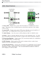
1
TM
D1V™ Rotary Control Panel
D4S™ Button Panel
™
PS Power Distribution Module
USER MANUAL
General Cautions & Warnings!
To prevent electrical shock or potential fire hazards, do not expose these products to moisture or
rain.
Before using this product, read the user manual for further warnings and cautions.
The following cautions should be carefully observed when installing, wiring, servicing or using this
product:
DO NOT remove the face plate/panel assembly of the unit. There are no user serviceable
parts on the circuit assembly. Refer service to qualified personnel.
DO NOT use solvents or other cleaners to clean the unit. Basic external care requires only
a damp cloth. Disconnect the power supply cabling before cleaning.
Read all safety and installation instructions and retain all documentation for further reference.
D Series panels should be installed so that its mounting position does not interfere with
proper ventilation.
This product should not be installed or placed near a source of heat.
Power supply cabling and associated connectors should be unplugged from the power
source when the unit is not used for long periods of time, or will be stored.
This product requires mounting with NEMA metal enclosures. Mounting this product in
open space, or in plastic enclosures is not recommended.
Care should be taken to ensure that the installation is clear of possible sources of contamination. Make sure that the product’s ventilation openings are not exposed to possible
sources of liquid, gases, or other contaminant.
This product should be inspected by a qualified service technician if the power supply
cabling or connectors have been damaged, if the unit has been dropped, or if a foreign
substance has gained access to the interior electronic and electrical components.
The information contained in this manual is subject to change without notice. Peavey Electronics
is not liable for improper installation or configuration. The information contained herein is
intended only as an aid to qualified personnel in the design, installation and maintenance of engineered audio systems. The installing contractor or end user is ultimately responsible for the successful implementation of these systems.
All creative content in this manual, including the layout, art design, content, photography, drawings, specifications and all other intellectual property is Copyright ® 2002 Peavey Electronics
Corporation. All Rights Reserved.
Manual by WR.
Contents
Welcome...............................................................................................4
What’s in the box?..................................................................................4
Products...............................................................................................5
Features & Applications...........................................................................5
D1V Panel Features................................................................................6
D4S Panel Features................................................................................7
Power Supply.........................................................................................8
PS Panel Features...................................................................................9
Installation..........................................................................................10
Connections.........................................................................................11
Configuring the Base Address.................................................................12
EOL Terminations.................................................................................13
Configuring buttons for Trigger Mode (4S Only).........................................14
Configuring buttons for Switch Mode (4S Only).........................................15
Base Address Chart (Address 1-77).........................................................16
Base Address Chart (Address 81-121).....................................................17
Welcome
Welcome
Thank you for adding D Series panels to your Architectural Acoustics® sound
system. The D Series flush-mount control panels are designed from the
ground up, specifically for the integrated systems contractor. In spite of
the multiple options for controlling Architectural Acoustics products, D
Series adds yet another dimension to end user interface.
You will find the combination of D Series and Architectural Acoustics sound
products an extremely powerful way to provide the end-user with an
intuitive, flexible and cost-effective control interface.
With some forethought, planning and good basic design, you can use
Architectural Acoustics products to maximize system functionality while
keeping costs down, maintaining high usability.
At press time, the D Series control panels are supported by the Digitool MX
Digital Audio Processor and the PZS 140R Multi-Zone Mixer Amplifier.
What’s in the box?
D Series panels are packaged in a single container and include the following
items:
• D4S or D1V flush-mount panel
• Black Phillips head countersunk 6-32 mounting screws (2)
• User manual (this manual)
The optional D Series PS power distribution module is packaged separately
and includes a 16.5 VAC power supply and this manual.
If any of these items are missing, please contact the Architectural Acoustics
Tech Support department.
PAGE 4
D Series™ User Manual
Products
Products
This manual covers the complete line of Architectural Acoustics D Series
control products.
• D4S
The D4S is a one-gang Decora™ panel with four programmable buttons and
status LEDS
• D1V
The D1V is a one-gang Decora panel with four programmable “virtual”
rotary controls and status LEDS
• PS
Power supply distribution module with mounting plate and integral EOL
termination
Features & Applications
•
•
•
•
•
•
•
Standard Decora package
Assignable controls
LED control status indicators
Label space for customization
RS-485 network connectivity
Easy wiring & installation
Flexible
•
•
•
•
•
•
•
Addressable
Tracking rotary control locations
Software upgradeable
Power supply card available
Low power requirements
Cost effective
Integral EOL Terminators
D Series controllers are designed for applications where simple end-user
control is required. Among the many applications where D Series panels
provide fundamental benefits are:
•
•
•
•
•
•
•
•
Conference Rooms
Meeting Rooms
Combinable Ballrooms
Paging Systems
Entertainment Systems
Theatre BOH (Back of House)
Bars & Restaurants
Schools
•
•
•
•
•
•
Medical Facilities
Institutional Facilities
Municipal Facilities
Courtrooms
Lecture Halls
Presentation Rooms
D Series™ User Manual
PAGE 5
Panel Features
D1V™ Panel Features
1
2
3
6
7
4
5
1. Zone LED - Single-color green LED illuminates to indicate the active
zone. The active zone is determined by successive pushes of the rotary
control knob.
2. Level LED - Single-color green LED array indicates current position of
rotary knob. An independent array exists for each zone.
3. Label Space - Use this area to affix adhesive label to identify zone.
4. Knob - Rotary encoder adjusts the level of the assigned zone. An integral momentary push-switch selects a single zone with successive pushes.
5. Mounting Bracket - Single-gang (1G) mounting bracket for installation
into standard NEMA 1G switch box.
6. DIP Switch - Eight-position DIP switch assigns button mode, base
address and EOL termination function.
7. RJ-45 Connectors - Dual RJ-45 connectors for installation into D Series
RS-485 network. These connectors are wired in parallel and include data
and power supply connections. The recommended termination media is
UTP Category 5 (CAT5) cable.
PAGE 6
D Series™ User Manual
Panel Features
D4S™ Panel Features
1
3
5
2
6
4
1. Label Space - Use this area to affix adhesive label to identify zone.
2. Zone LED - Single-color green LED illuminates to indicate the active
zone. The LED function is dependent on the button mode (see page 15).
3. Zone Switch - Momentary push button. Depending on the switch
configuration, this switch will either select a mutually exclusive input/output
or add to a group of four signals.
4. Mounting Bracket - Single-gang (1G) mounting bracket for installation
into standard NEMA 1G switch box.
5. DIP Switch - Eight-position DIP switch assigns button mode, base
address and EOL termination function.
6. RJ-45 Connectors - Dual RJ-45 connectors for installation into D Series
RS-485 network. These connectors are wired in parallel and include data
and power supply connections. The recommended termination media is
UTP Category 5 (CAT5) cable.
D Series™ User Manual
PAGE 7
Power Supply
Power Supply
The D Series control panels are active electronic devices, and therefore
require a low voltage power supply to function. To properly distribute the
low-voltage power required to operate a network with multiple panels, the
D Series PS power supply distribution module is required. The D Series PS
includes a 16.5 VAC “wall wart” style low voltage power supply, which
distributes the power to the panel network.
Although the PS module includes an AC power supply, the D Series panels
operate with either DC or AC power supplies. When using a DC power
supply, the voltage should be between 12V and 24V DC and be capable of
supplying enough current for the total number of panels for the installation.
For AC power systems, the voltage range is 9-16 VAC. Each panel draws
approximately 15mA. Care should be taken to ensure that multiple panels
and their associated cabling do not exceed the capability of the power supply.
PAGE 8
D Series™ User Manual
Power Supply
PS Panel Features
1
3
2
4
1. EOL Jumper - Two-position jumper for configuring EOL (end-of-line)
terminating circuit. Placing the supplied shorting pin on this jumper will
enable an RC circuit across the RS-485 positive and negative data
conductors.
2. RJ-45 Connectors - Two female RJ-45 connectors wired in parallel for
distribution of low voltage power. Typically, one connector terminates the
control port of the audio processor and the distant control network
terminates at the other connector.
3. Power Supply Input Connector - Female pin jack for terminating the
including 16.5 VAC power supply unit. The power range is 12-24 VDC or
9-16 VAC.
4. Mounting plate - Powder-coated CRS mounting plate.
D Series User Manual
PAGE 9
Installation
Installation
D Series panels are designed to mount in standard NEMA electrical
enclosures. This includes boxes designed for fixed installation into sheet
rock, wood or masonry construction. All cabling and terminations should
be installed into conduit, securely coupled to the mounting box and system
ground plane.
EMT conduit systems are
recommended for
commercial and industrial
applications or in adverse
environments.
For a proper finish,
use only Decora™ style
cover plates to match
the box gang size.
PAGE 10
D Series™ User Manual
Connections
Connections
Implementing D Series control panels requires a separate wiring
infrastructure that includes RS-485 data and low voltage power in a bus or
“daisy chain” topology. For best performance and reliability, only Category
5 (CAT 5) cable should be used for D Series networks. Cable runs
exceeding 2000’ are possible using CAT 5 cable, proper conduit and
terminations.
In some cases, especially when extremely long cable runs are present, it
may be necessary to terminate the end of the data line (EOL). The D
Series PS power distribution module includes the proper terminating circuit
and is jumper-selectable for such cases. In adverse conditions, both ends
of the data line may require EOL termination. If this is the case, you can
terminate the far end of the network by enabling an additional EOL
termination at the last panel in the string with the DIP switch. (See page
13.)
The illustration below shows a typical example of how the control network
should be configured using a Digitool™ MX processor.
To other panels
D Series™ User Manual
PAGE 11
Configuration
Configuring the Base Address
In a D Series control system, each panel on the network must have a Base
Address. The Base Address places a group of four absolute controls into a
“sequence” that allows the system software to identify each control
function. For the D4S™ these controls are buttons and for the D1V™, they
are rotary controls. Each Base Address includes four adjacent controls and
there are 32 Base Addresses available on a single network. An address can
be unique for each panel in a system, or multiple panels with the same
control function can share a single address. These are unique Base
Addresses, not panels. In other words, if you have several panels that
share the same Base Address, they count as one.
To set the Base Address, configure DIP switches 3-7 for the desired address
number. Only switches 3 through 7 are used for the Base Address. A
complete table of Base Address settings can be found on pages 16 and 17.
Base Address Switches
It is important to note that Base Addresses act together in a mutually
exclusive group of four adjacent addresses. This is especially important
when using the D4S. Placing multiple D4S control panels in the same
group of Base Addresses will allow for a large number of mutually exclusive
buttons. For example, if four D4S panels are configured for Trigger Mode
and set for adjacent Base Addresses within the same group, the combined
panels will provided sixteen mutually exclusive buttons, where only one
button could be active at a time. Likewise, if independent trigger operation
is required, the panels should be set with Base Addresses from separate
groups (see pages 16 & 17).
PAGE 12
D Series™ User Manual
Configuration
EOL Terminations
As mentioned on page 11, the PS power supply distribution module includes
an integral EOL (end-of-line) terminating circuit. However, in adverse
conditions, it may be necessary to terminate both ends of the control
network.
In addition to the terminator on the PS module, each panel includes an
integral terminating circuit that can be activated by setting DIP switch 8 to
the ON position.
Enabling both the PS and panel terminators, you can terminate both ends
of the control data network. This is the best method to ensure that your
data cabling is secure from unwanted interference or noise that could affect
data transfer performance.
EOL Termination Switch
Terminated
Open
D Series™ User Manual
PAGE 13
Configuration
Configuring buttons for Trigger Mode (D4S™ Only)
The buttons on the D4S are always a set and can be configured as
“Triggers” or “Switches”. In Trigger mode, each button transmits a
momentary signal when pressed. This signal is a “one-shot” command that
the software recognizes as a trigger. A trigger has no ON or OFF state, it is
simply a momentary logic signal. When a trigger has been activated, the
button’s LED will illuminate and stay illuminated until another trigger in the
same group is activated. In other words, the four buttons and their
associated LEDs are “mutually exclusive”. (See page 12 for information
about mutually exclusive Base Addresses.)
Before attempting to configure the D4S, make sure that your system is
completely wired and terminated correctly to the audio processing product.
The power should be ON for both the processor and the D Series network.
Configuring the D4S is accomplished by adjusting the rear panel DIP
switch. The DIP switch includes eight two-position switches, labeled 1-8.
There are three basic groups of switches that provide the configuration
functionality for the D4S. Switch 1 determines Function/Type, switches 3-7
determine Base Address (see page 12) and switch 8 toggles the EOL
terminating circuit on and off (see page 13). Switch 2 is not used.
Each switch in the DIP package has two positions, ON and OFF. The
switches are adjusted correctly when the cap is at either end of the slot. A
switch that is in the center of its travel is not adjusted correctly.
To configure the D4S for trigger operation, set DIP switch 1 as shown in the
illustration below:
Button Function switch (shown in Trigger Mode)
PAGE 14
D Series™ User Manual
Configuration
Configuring buttons for Switch Mode (D4S™ Only)
When the buttons are configured as
switches, each button is independent and
no longer acts as part of a mutually
exclusive group. The button sends
alternate ON and OFF commands with each
button press. The LED indicates the
ON/OFF status for each button separately.
The buttons can be set
for trigger OR switch
operation only. You
cannot mix function in a
single button group.
This feature is used primarily to turn ON specific audio functions, such as a
mute, or in conjunction with level controls, switches and simple audio
routing.
To configure the D4S for switch operation, set DIP switch 1 as shown in the
illustration below:
Button Function switch (shown in Switch Mode)
D Series™ User Manual
PAGE 15
Base Address
Base Address Chart (Address 1-77)
DIP Switches
Base Address
DIP Switches
Address/ID Sequence
1
41
5
45
9
49
13
53
17
57
21
61
25
65
29
69
33
73
37
77
3 4 5 6 7
3 4 5 6 7
PAGE 16
D Series™ User Manual
Base Address
Base Address Chart (Address 81-121)
DIP Switches
Address/ID Sequence
DIP Switches
Address/ID Sequence
3 4 5 6 7
81
121
85
Not Used
89
Dividing lines indicate
Base Address groups
where mutually exclusive
operation is possible
using the D4S™.
93
97
101
105
109
113
117
D Series™ User Manual
PAGE 17
Architectural Acoustics®
A Division of Peavey Electronics Corp.
711 A St., Meridian, Mississippi 39301
601-483-5376
http://aa.peavey.com
Features & specifications subject to change without notice
Copyright © 2002, All Rights Reserved
Printed in the USA