1
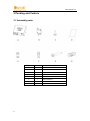
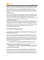
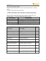
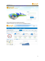
User Manual V1.3 User Operating Manual Model Number: PIU4K User Manual V1.3 This manual is an integral part of the unit. Please read the instruction manual carefully before installation, operation or maintenance. Keep this instruction manual for future reference. This document is not to be reproduced in any manner, nor are the contents to be disclosed to anyone, without the express authorization of Omnik. User Manual V1.3 Catalog 1 Read This First ................................................................................................................................ 2 2 Symbols in the manual ................................................................................................................... 3 2.1 Safety symbols..................................................................................................................... 3 2.2 Other Symbols ..................................................................................................................... 3 2.3 Technical competence ......................................................................................................... 5 2.4 Safety Instructions ............................................................................................................... 6 3 Packing and Feature ....................................................................................................................... 8 3.1 Assembly parts .................................................................................................................... 8 3.2 Structure of Micro-Kit ......................................................................................................... 9 3.3 Main functions .................................................................................................................... 9 3.3.1 Basic protection functions........................................................................................ 9 3.3.2 Plant monitoring functions..................................................................................... 12 3.4 Technical Parameters ........................................................................................................ 13 4 Installation.................................................................................................................................... 13 4.1 Operating Condition .......................................................................................................... 13 4.2 System diagram ................................................................................................................. 14 4.3 Installation Procedure ....................................................................................................... 15 5 Operating Static ............................................................................................................................ 21 5.1 Working Mode................................................................................................................... 21 5.2 Grid-Connection ................................................................................................................ 22 5.3 Grid Disconnect ................................................................................................................. 22 5.4 Installation checklist .......................................................................................................... 23 5.5 Start-Up– Checks ............................................................................................................... 24 6 Disconnecting a Micro-Kit from the system ................................................................................. 25 7 Monitoring and Troubleshooting and Maintenance .................................................................... 26 7.1 Safety checks ..................................................................................................................... 26 7.2 Maintain periodically......................................................................................................... 26 7.3 Micro-Kit Status LED Indications and Error Reporting....................................................... 27 7.4 Internet WEB ..................................................................................................................... 28 8. Contact ........................................................................................................................................ 31 Appendix ......................................................................................................................................... 32 1 User Manual V1.3 1 Read This First Thank you for selecting Omnik new energy– a leading supplier of micro-inverter products for the solar PV market. Omnik’s new product “Micro-Kit” acts as the power interface (PI) to the utility grid. It is a separate device installed at the coupling point to the utility grid to provide the safety functions such as over/under voltage, over/under frequency, and especially active anti-islanding as well as lightning protection and line impedance stabilizing network (LISN), modular design. The data of real-time performance information of energy harvest for all Omnik micro-inverter systems can be collected by Omnik’s built in energy terminal unit Energy Terminal Unit (ETU) ”, and be transmitted to Omnik Solar Energy Data Acquisition System (SEDAS) to achieve a global data monitoring for PV power plant. This user manual includes Micro-Kit overview, installation, operation instruction and technical parameters. To assure properly installation and operation, please carefully read this user manual before installation, and pay attention to the caution symbol affixed on the product. Please hand this user manual to the end user. 2 User Manual V1.3 2 Symbols in the manual 2.1 Safety symbols Warnings and cautions tell you about the dangerous conditions that can occur if you do not follow all instructions in this manual. Please read following safety symbols to indicate dangerous conditions and important safety instruction. DANGER The DANGER symbols in this manual and on the Micro-Kit Indicate a hazard with a high level of risk which if not avoided, will result in death or serious injury. WARNING The WARNING symbols in this manual and on the Micro-Kit indicate ahazard with a medium level of risk which if not avoided, could result in death or serious injury. CAUTION The CAUTION symbols in this manual and on Micro-Kit indicate a hazard with a low level of risk which if not avoided, could result in minor or moderate injury. NOTE The NOTE symbols in this manual indicate the important product information. 2.2 Other Symbols Some Symbols replace words on the equipment, on a display, or in manuals. Trademark 3 User Manual V1.3 No access for unauthorized personal Caution, risk of danger Symbol for the marking of electrical and electronics devices according to Directive 2002/96/EC. Indicates that the device, accessories and the packaging must not be disposed as unsorted municipal waste and must be collected separately at the end of the usage Please follow Local Ordinances or Regulations for disposal or contact an authorized representative of the manufacturer for information concerning the decommissioning of equipment. Direct current Alternating current PE Protective conductor Earth(ground)TERMINAL Protective conductor Terminal Fuse Refer to the operating instructions Caution, risk of electric shock CE mark is attached to the solar Micro-Kit to verify that the unit follows the provisions of the European Low Voltage and EMC Directives 4 User Manual V1.3 PV Photovoltaic + DC terminal, indicating the polarity of the connections, positive, all positive connections shall be made with Red insulated wire _ DC terminal, indicating the polarity of the connections, negative, all negative connections with black insulated wires PCS Power conversion equipment, hereby is our DC/AC inverter SERVICE PERSONNEL Qualified personnel DVC Closed Electrical Operating Area A person having appropriate technical training and experience necessary to be aware of hazards to which that person may be exposed in performing a task and of measures to minimize risks to that person or other persons Person adequately advised or supervised by an electrically skilled person to enable him or her to perceive risks and to avoid hazards which electricity can create. For the purpose of the safety information of this manual, a "qualified person" is someone who is familiar with requirements for safety, refrigeration system and EMC and is authorized to energize, ground, and tag equipment, systems, and circuits in accordance with established safety procedures. The Micro-Kit and endues system may only be commissioned and operated by qualified personnel. Decisive voltage class Room or location for electrical equipment to which access is restricted to skilled or instructed persons by the opening of a door or the removal of a barrier by the use of a key or tool and which is clearly marked by appropriate warning signs 2.3 Technical competence The procedures described in this manual should be performed by trained and authorized personnel only. Maintenance should only be undertaken by competent individuals who have a general knowledge of and experience with devices of this nature. No repairs should ever be undertaken 5 User Manual V1.3 or attempted by anyone not having such qualifications. Compliance with safety regulations depends upon installing and configuring system correctly, including using the specified wirings. Only professional assemblers who are familiar with requirements for safety, Photovoltaic system and EMC must install the system. The assembler is responsible for ensuring that the end system complies with all the relevant laws in the country where it is to be used. Omnik require using only genuine replacement parts, manufactured or sold by Omnik for all repair parts replacements. Read completely through each step in every procedure before starting the procedure; any exceptions may result in a failure to properly and safely complete the attempted procedure. Servicing of this product in accordance with this manual should never be undertaken in the absence of proper tools, test equipment and the most recent revision to this manual, which is clearly and thoroughly understood. 2.4 Safety Instructions This chapter contains the safety instructions that you must follow when installing, operating and servicing the unit. If ignored, physical injury or death may follow, or damage may occur to the unit. Read the safety instructions before you commence work on the unit. If you are unable to understand the Dangers, Warnings, Cautions or Instructions, contact the manufacturer or an authorized service dealer before installing, operating and servicing the unit. To ensure your personal safety and the proper use of Micro-Kit, please carefully read this manual before installation. If the product is damaged when installation not comply with this manual, Omnik do not respond for any quality assurance and other risks. For Omnik Micro-Kit Warranty Terms and Conditions, see the appendix of this manual. • Be aware that only qualified personnel should install and /or replace Omnik Micro-Kit. • Perform all electrical installations in accordance with all local electrical codes. • Comply the rules of correctly use of tools and personal protective equipment (PPE) for insuring the Micro-Kit safe running. 6 User Manual V1.3 • Be aware that only qualified personnel should maintain Omnik Micro-Kit. • Connection of any photovoltaic system to the electrical utility grid should only commence after receiving prior approval from the utility company. • The Micro-Kit MUST be installed and debugged complying with this manual by the professional authorized by Omnik. • All electrical installation MUST meet the local standard. • To assure the safe running, must comply with the relative standard for using the tool properly and Personal Protective Equipment (PPE). Away from the chemical and reagent. • The Micro-Kit must installed environments suitable for it’s IP rating. • CAUTION! The device is intended for fixed installation, Located on a part that is not removable without impairing the operation of the unit. • CAUTION! Visible and legible to the operator during the normal operation of the device. • WARNINGS - Risk of electric shock- Do not open cover. No user serviceable parts inside. Servicing limited to qualified service personnel. • WARNINGS - The printed circuit boards contain components sensitive to electrostatic discharge. Wear a grounding wrist band when handling the boards. Do not touch the boards unnecessarily. • WARNINGS - Do not operate any device which is damaged, lacking parts or dented. Failure to observe this warning may result in an electric shock, injury, fire or accident. • WARNINGS - Before installing the unit, agree with the customer the site. • WARNINGS - The output connection with AC grid shall be protected by a max. 20A circuit breaker. • The PIU4K-230-AU shall be connected with the Omnik M248A-230-AU inverter as a system. It cannot operate as a stand-alone unit or in case of AC grid disruption WARNING: Be aware that the input AC voltage of the Omnik Micro-Kit shall not exceed the rated voltage; higher voltage may cause permanent damage to the device. It contains no user serviceable and Omnik- Micro-Kit Warranty parts. CAUTION: SAVE THESE INSTRUCTIONS– This manual contains important instructions for Micro-Kit that shall be followed during installation and maintenance. Warning: Only authorized persons can be allowed for installation of inverter 7 User Manual V1.3 3 Packing and Feature 3.1 Assembly parts 8 Object Quantity Description A 1 Micro-Kit B 1 Bracket C 1 M4X8 Screw D 1 User manual E 1 AC Bus connector F 1 Grid connector G 3 ST6X50 Screw H 3 Expansion tube User Manual V1.3 3.2 Structure of Micro-Kit 1 Cover 2 RJ45 socket 3 Base 4 USB socket 5 Display screen 6 Mounting plate 7 Output socket 8 Input socket Note: If the Ethernet Cable and Can bus Cable are not connected, no holes of outlets shall be opened. 3.3 Main functions 3.3.1 Basic protection functions • Over/Under Voltage protection Micro-Kit _DSP1 sample the real time voltage signal of one grid period, and get the current grid frequency by Lock-in Algorithm, compare the signal with 9 User Manual V1.3 Grid_ frequency_ max, Grid_ frequency _min. If the signal is more than Grid_ frequency_ max or less than Grid_ frequency _min, Micro-Kit _DSP1 will disconnect the relay connected to the grid within 2S, and all the micro-inverters will stop working. If the signal is less than Grid_ frequency_ max and more than Grid_ frequency _min, Micro-Kit _DSP1 will connect the relay in 60~180S, all the micro-inverters will start working again. Figure 3.3.1 under/over voltage protection flow chart • Over/Under Frequency protection Micro-Kit _DSP1 sample the real time voltage signal of one grid period, and get the current grid voltage by Lock-in Algorithm, compare the signal with Grid_voltage_max, Grid_voltage_min. If the signal is more than Grid_voltage_max or less than Grid_voltage_min, Micro-Kit _DSP1 will disconnect the relay connected to the grid within 2S, and all the micro-inverters will stop working. If the signal is less than Grid_ voltage_ max and more than Grid_ voltage_ min, Micro-Kit _DSP1 will connect the relay in 60~180S, all the micro-inverters will start working again. 10 User Manual V1.3 Figure 3.3.2 under/over frequency protection flow chart • Over Current Protection: If the output over current caused by internal fault of M248 is occurred, the fuse will be open to disconnect the M248 and grid, the LED will be flickered at the same time. Micro-Kit _DSP1 sample the real time current signal of one grid period, and get the current grid current by Lock-in Algorithm, compare the signal with Grid_ current_ max. If the signal is more than Grid_ current_ max, Micro-Kit _DSP1 will disconnect the relay connected to the grid within 2S, and all the micro-inverters will stop working. If the signal is less than Grid_ current_ max, Micro-Kit _DSP1 will connect the relay in 60~180S, all the micro-inverters will start working again. • Short Circuit Protection: M248 sample the real time voltage signal of one grid period, and get the current grid voltage by Lock-in Algorithm. If the grid is short circuit, Lock-in Algorithm will be failed and M248 will stop working within 2S, and have a fault alert by LED. Micro-Kit _DSP1 sample the real time voltage signal of one grid period, and get the current grid voltage by Lock-in Algorithm, If the grid is short circuit, Lock-in Algorithm will be failed and Micro-Kit _DSP1 will disconnect the relay connected to the grid within 2S, and all the micro-inverters will stop working. • Anti- Islanding Protection M248 increase the reactive distortion to the output current at normal operating 11 User Manual V1.3 conditions, and all the M248 are same connection to keep the consistency of distortion. Micro-Kit _DSP1 sample the real time voltage signal of one grid period, and get the current grid reactive power by Lock-in Algorithm, compare the signal with Grid_VA_max, the reactive power detected is more than Grid_VA_max if the system is islanding, and Micro-Kit _DSP1 will disconnect the relay connected to the grid within 2S, and all the micro-inverters will stop working. •DC Injection(1A): Micro-Kit _DSP1 sample the real time current signal of one grid period, and get the current grid DC injection by FFT Algorithm, compare the signal with Grid_ current0_ max (equivalent to 1A), If the DC injection is more than Grid_ current0_ max, Micro-Kit _DSP1 will disconnect the relay connected to the grid within 2S, and all the micro-inverters will stop working. •Leakage Current (30mA): Micro-Kit _DSP1 sample the real time current signal of one grid period through differential current sensor, and get the current grid leakage current directly, compare the signal with Grid_ leakage_ current_ max (equivalent to 30mA), If the DC injection is more than Grid_ leakage_ current_ max, Micro-Kit _DSP1 will disconnect the relay connected to the grid within 2S, and all the micro-inverters will stop working. 3.3.2 Plant monitoring functions • Use the Power Line Carrier Communication (PLCC) technology within Photovoltaic power plant By PLCC technology, Micro-Kit collects generation data from the PV power plant, and transmits to the central database by its built in ETU. Measures the data of energy harvest by high-precision digital power meter by high-precision digital power meter, Micro-Kit measures the data of energy harvest to achieve the photovoltaic power plant status monitoring, and transmits the collected data to central database by eLog. • High-Frequency Line Impedance Stabilization Network (LISN) By high frequency LISN integrated, Micro-Kit can improve the immunity, but also effectively prevent the Micro-Kit interference to the grid. • Uses CAN-bus to connect every single power interface Micro-Kit to realize power data monitoring Every Micro-Kit connect with others through CAN-bus. Photovoltaic power generation data can be collected by embedded component, ETU, which is connected with internet and central database and transmitted data to central database. Solar Energy Data Acquisition System (SEDAS) analyses the data. 12 User Manual V1.3 3.4 Technical Parameters Model PIU4K Data (AC) Rated switched power Rated voltage Rated current voltage range frequency range 3.68KW 230V 16A 195V ~ 253V (Adjustable With Country Deviation) 49Hz ~ 51Hz (Adjustable With Country Deviation) Electrical Portal Grid and Array Grid Array Double Relay Connect to Grid Connect to Array Mechanical Data Enclosure environmental rating Operating temperature range Dimensions (WxHxD) in mm Weight IP40 -20℃~65℃ 212x209x81mm 1.5kg Features Compliance Warranty Power Consumption CQC/TUV/DK5940/G83/SEMKO/ETL 5 Years 6W 4 Installation 4.1 Operating Condition Operating Temperature Ambient temperature: -20℃~﹢65℃。 Operating Humidity Air Relative Humidity <=90% Rated Input AC230V/50Hz 13 User Manual V1.3 4.2 System diagram Figure 4.2 System diagram 14 User Manual V1.3 4.3 Installation Procedure Dimension See below Figure 4.3.1. Figure 4.3.1 Dimension of Micro-Kit Warning • Micro-Kit MUST connect to earth effectively. • To comply with local installation of the safety practices and guidelines, and shall comply with the proper use of tools and personal protective equipment (PPE) requirements. Caution Between the cables, power supply cable and CAN Bus, and RJ-45 cable to the internet (if optional), must be isolated from each other. Do not place these cables in the same rack. 15 User Manual V1.3 Installation Diagram See below Figure 4.3.2. Figure 4.3.2 Installation Diagram Step 1: Connect the plants terminal to AC BUS Cable. Step 2: Connect the grid terminal to the Grid. Step 3: Connect the USB terminal of Micro-Kit to Debug-COM. Step 4: Connect the RJ45 terminal of Micro-Kit to the Ethernet devices connected to the Internet or network card on the PC (Optional). Pin1-White Pin2-Brown Pin3-Green Pin4-NC White - N Black - L Green - PE Table 4.3.1 AC Input Terminal Note: CAN bus terminal, grid terminal, plants terminal are all standard component. Be connected to relative terminal. 16 User Manual V1.3 Grid connection 1. Wire fastening and split Screw connection: Tightening torque typically 0.8Nm-1.0Nm 2. Connector fastening and split 3. Connector Locking and split 17 User Manual V1.3 Installation program 1. Drill three holes in the wall as following figure. 18 User Manual V1.3 2. PlaceΦ 12mm expansion tubes in every hole by rubber hammer, then fix the bracket to the wall with 3 ST6X50 screws. 3. Connect Micro-Kit to bracket as following figure. 19 User Manual V1.3 4. Fasten Micro-Kit and bracket with M4X8 screw. 20 User Manual V1.3 5 Operating Static Energy data terminal ETU is the core component of the world‟s first Power Plant Interface (PPI) created by Omnik, it realizes the connection between solar power plant and internet. As an intelligent communication gateway, ETU uses Omnik’s Power Line Communication (PLC) technology to continuously monitor the data of energy harvest of solar power plant such as power, voltage, current and frequency; it can also transmit the real-time data of energy harvest to Omnik‟s Solar Energy Data Acquisition System (SEDAS) to realize the monitoring around the world. Set aside a minimum functionality of the ETU module in the Micro-Kit, you can optional this ETU modules to achieve the connection between PV power plant and the Internet. RJ45 cable should be simultaneously matching with ETU module. 5.1 Working Mode The working modes of an Omnik Micro-Inverter are: Start up Active Fault Standby The detailed working mode descriptions are as below: Start up Start up mode is for a newly installed Micro-Kit. This startup mode must base on the proper AC, micro-inverter, Ethernet and Can bus cables connecting. Active When the Micro-Kit is in normal operation process, this insures that the power available from micro-inverter array is exported to the utility grid. The LED inside of Micro-Kit will flash in green. Fault If the system does not operate correctly, Omnik Micro-Kit would stop automatically and enter into Disable mode. The Omnik Micro-Kit system keeps detecting the disable information, it will be in disable mode until fault release. If the inoperative Micro-Kit has been repaired and match to the electrical utility grid, the whole system would enter operation mode after 60 seconds to 5 minutes. Be aware that only qualified personnel should maintain the OMNIK Micro-Inverters. The LED will flash in yellow (communication fault) or red. Standby When the Micro-Kit is in operation process but keeps with low voltage and 21 User Manual V1.3 current in micro-inverter side for a certain time. The Micro-Kit manages transition from “Active” to “Standby”. In “standby” mode, Micro- Inverters keep detecting the energy output of each micro-inverter. When the output energy reaches the power generation conditions, the inverter would enter into “Active” from the “Standby” state. • The equipment maintenance only can be carried through by service department of Omnik, or the service centre or professional authorized by Omnik. Maintenance personnel should be familiar with all the warnings in this manual and the proposed steps • Must be sure to disconnect the input and output power before removal of equipment for maintenance. 5.2 Grid-Connection Micro-Kit system connects grid automatically. It detects and monitors the performance of each PV module through each micro-inverter. When the output energy reaches the power generation conditions, the Micro-Kit system begin connect grid and generate electricity. 5.3 Grid Disconnect If the state grid cannot match the following situations (table 5.3.1), it bring the Omnik Micro-Inter to a rest. Type Rated Variation Range Voltage 230V 205V - 265V Frequency 50Hz 47Hz – 51Hz Table 5.3.1 Parameter of European state power grid Only to be carried out by qualified competent personnel. Start Micro-Kit after checking all below steps: WARNING Connect the Micro-Kit to the electrical utility grid only after receiving prior approval from the utility company. 22 User Manual V1.3 WARNING Only qualified personnel could connect Omnik Micro-Kit to the electrical utility grid. 5.4 Installation checklist To ensure the safe operation of the devices, they may be installed and commissioned only by qualified personnel in full compliance with the warnings referred to in this manual. Checklist Check the mechanical and electrical installation of the unit before startup. Go through the checklist below together with another person. Read the Safety instructions and EC directives on the previous pages of this manual before you work on the unit. Mechanical Installation Check screw connections on the inverter for tightness. The ambient operating conditions are allowed. (See Technical parameter); The unit is fixed properly on a nonflammable wall. (See Mechanical installation.) The cooling air will flow freely. The unit is fixed tightly and support is enough. (See Mechanical installation.) Electrical Installation Check all screws of the connection terminals in the installation system before and after the inverter for tightness. The AC output voltage matches the unit nominal voltage. Make sure that the whole micro-inverters array power cannot exceed the permissible input power range of the device The micro-inverter output cable and Micro-Kit input cable‟s connections and their tightening torques are OK. There are no tools, foreign objects or dust from drilling inside the unit. Unit, connection box and other covers are in place. The Micro-Kit output power cable and the main power connection is OK. The Ethernet and Can bus (more than 2 Micro-Kit) connections are OK. The external cords and cables are fixed tightly, and strain relief clamp is provided for external accessible cords and cables。 Cord and cable inlets are sealed completely after cord/cable installation. 23 User Manual V1.3 5.5 Start-Up– Checks The device has been checked at the factory and adjusted so that it can be commissioned immediately after being installed. Following Section Installation checklist, for your personal safety and to avoid damage, the following safety checks should be performed before start by a qualified person who has adequate training, knowledge, and practical experience to perform these tests. The data should be recorded in an equipment log. If the device is not functioning properly or fails any of tests, the device has to be repaired. 1. Inspect the equipment and accessories for mechanical and functional damage. 2. Inspect the safety relevant labels for legibility. 3. Inspect the fuse to verify compliance with rated current and breaking characteristics. 4. Measurement of insulation resistance 5. Measurement of earth resistance 6. Mounting structures: Verify tightness and integrity of bolts and other fastening devices; Verify if there is significant corrosion. 24 User Manual V1.3 6 Disconnecting a Micro-Kit from the system To ensure safe disconnection of the Micro-Kit from the solar power plant, it must NOT be carried out under load conditions. Ensure the following disconnection steps are carried out in the order shown: 1. Disconnect the AC by isolating the branch via the circuit breaker. 2. Disconnect the AC cable from micro-inverter in the branch circuit. 3. Make sure the LED inside of Micro-Kit is off. 4. Disconnect the Ethernet and CAN bus cable. 5. Remove the Micro-Kit from the system. 25 User Manual V1.3 7 Monitoring and Troubleshooting and Maintenance No use-serviceable parts inside, before servicing and in the event of internal malfunction the unit, send the Micro-Kit to authorized representative or manufacturer! Never operate this product and change any part of Micro-Kit yourself. Only trained and authorized professional personnel WHO ARE FAMTLIAR WITH THE REQUIREMENTS OF SAFETY was allowed to perform servicing and maintenance work. 7.1 Safety checks Safety checks should be performed at least every 12 months by manufacturer’s qualified person who has adequate training, knowledge, and practical experience to perform these tests. The data should be recorded in an equipment log. If the device is not functioning properly or fails any of tests, the device has to be repaired. For safety check details, refer to this manual, section 3 Safety instruction and EC Directives. 7.2 Maintain periodically Only qualified person may perform the following works. During the process of using the Micro-Kit, the manage person shall examine and maintain the machine regularly. The concrete operations are as follow. 1. Check the SEDAS (Solar Energy Data Acquisition System) website if the indicators the Micro-Kits are in normal state. This check should be performed at least every 6 months. 2. Check if the input and output wires are damaged or aged. This check should be performed at least every 6 months. 26 User Manual V1.3 Before cleaning the Micro-Kit: Wear gloves and safety glasses. Disconnect grid cable and micro-inverter’s cable with Micro-Kit – Isolating device. Clean the inverter with wet cloth carefully. 7.3 Micro-Kit Status LED Indications and Error Reporting Micro-Kit has an inside LED to indicate the status of the Micro-Kit. The following table 7.3.1 is the LED indications and error report. LED Operation Working Mode 2 short yellow blinks startup Flashing yellow continuously Producing power and communicating with ETU 4 short yellow blinks Producing power and not communicating with ETU 6 short yellow blinks Disable 3 short yellow blinks Standby Table 7.3.1Status LED Indications and Error Reporting Fields Grid Voltage Explain Grid Voltage Unit V Grid Current Export DC A Grid Frequency Grid Frequency Hz DC input voltage DC input voltage V DC Input DC A Power Output Power W Temperature Ambient temperature °C Module Temperature M248 Module Temperature °C Daily Working Hours Daily power generation Working Hours for the day generation power for the day Minute kWH Monthly power generation Daily power generation for the month kWH Amount of power generation Amount of power generation kWH Amount of working hours Hour Amount of working hours Diagram 7-3-1 Details Control Information 27 User Manual V1.3 Fields Module Disable Explain M248 module disable in the PV system Over temperature M248 over temperature in the PV system Over current PV module export over current Over DC voltage Over DC voltage in PV module Over AC voltage Over voltage in state grid Low voltage Low voltage in state grid Frequency disable Abnormal frequency in state grid Island effect Anti-island protection Diagram 7-3-2 Information of Disable Mode NOTE Disable Micro-Inverter does not affect the operation of all Omnik Micro-Inverter system. System will bypass the disable Micro-Inverter. WARNING Be aware that only qualified personnel should troubleshoot the PV array or the Omnik Micro-Inverter. WARNING Never disconnect the DC wire connectors under load. Ensure that no current is flowing in the DC wires prior to disconnecting. 7.4 Internet WEB Introduction Use The monitoring website developed by Omnik to real time track the statistics information of the energy harvest for all Omnik micro-inverter system and monitor per-module’s performance which is integrated into the Omnik micro-inverter system. 28 User Manual V1.3 Register address:http://221.131.118.124:28080 Data collector Micro-Kit registers procedure: Register Succeed, log on and enter the webpage as below: 29 User Manual V1.3 click“settings”,and enter the Micro-Kit register page: click “device” At the last part of the page, click “add”, fulfill the Micro-Kit serial Number in the blank space, for example:“90000001”, click “OK” and finish the register of the data collector. 30 User Manual V1.3 8. Contact Suzhou Headquarter Xinghu Road No.218 bioBAY Park C2-101 215123 Suzhou China Tel: +86 512 6295 6676 Fax: +86 512 6295 6682 Email: [email protected] www.Omnik-solar.com Omnik German Service Center An der Pikardie 6 01277 Dresden Deutschland Tel: +49 (0)351 30986031 Fax: +49 (0)351 30930022 Email: [email protected] Service line Tel: +86 512 6295 6676 Fax: +86 512 6295 6682 Email: [email protected] 31 User Manual V1.3 Appendix Limited Warranty OMNIK provides the 5-year warranty (The exact time depends on the contract) due to our responsible attitudes toward customers and partners and our confidence in OMNIK products. During the warranty period, if any defect in workmanship and materials of the Omnik micro-inverters is detected, customers is entitled by the warranty to ask for replacement or repairing from Omnik with no extra cost. During the Warranty period, require the product invoices and purchase date for free replacement or repairing. The Limited Warranty does not cover the product which trademark is not visible. The Limited Warranty does not cover following situations: Damaged by transportation Improperly installed Improperly operated Improperly handled or used Use under conditions for which the product was not designed or in an unsuitable environment. Any installation and use beyond the scope of relevant international standards Damage cause by non-normal natural environment 32