1
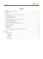
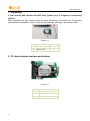
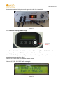
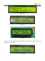
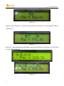
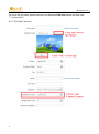
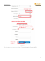
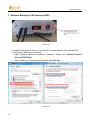
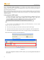
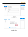
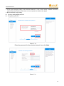
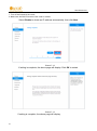
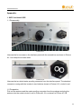
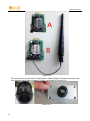
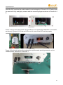
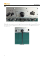
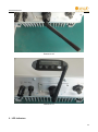
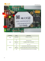
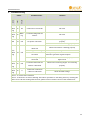
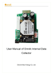
User Manual V2.5.1 User Manual of Omnik Internal Data Collector Omnik New Energy Co.,Ltd. User Manual V2.5.1 Catalog 1. Unpacking ..................................................................................................................................................................... 2 2. PV data collector interface and buttons ........................................................................................................................ 2 3. Set up antenna.............................................................................................................................................................. 3 4. S/N Label ...................................................................................................................................................................... 3 5. Connect the PV data collector to the inverter (Shown in Picture 5-1) ........................................................................... 3 5.1 Connection .............................................................................................................................................................. 3 5.2 IP Address Display and settings .............................................................................................................................. 4 6. Register on monitoring website ..................................................................................................................................... 7 6.1 Click Register button to go to registering interface for new account ....................................................................... 7 6.2 Fill in user’s information as required ....................................................................................................................... 7 6.2.1 “End User” Account...................................................................................................................................... 8 7. Network Settings (In AP mode by WiFi) ...................................................................................................................... 10 8. Login the PV monitoring system to manage the power station ................................................................................... 19 8.1 “End User” User Interface ..................................................................................................................................... 19 9. IPhone & iPad application ........................................................................................................................................... 24 9.1 Auto Mode: ............................................................................................................................................................ 24 9.2 Manual Mode ........................................................................................................................................................ 26 9.2.1 Step for monitoring without Internet connection (Manual Mode) ................................................................ 26 9.2.2 Features ............................................................................................................................................. 26 10. Contact........................................................................................................................................................................ 28 Appendix. ............................................................................................................................................................................ 29 1. WiFi Card Install SOP ............................................................................................................................................. 29 1.1 Disassembly ................................................................................................................................................. 29 1.2 Preparation ................................................................................................................................................... 29 1.3 Installation .................................................................................................................................................... 31 2. LED Indicators .................................................................................................................................................... 33 3. Troubleshooting .................................................................................................................................................. 35 1 User Manual V2.5.1 1. Unpacking If your inverter had installed the WiFi card, please go to 6. Register on monitoring website. After unpacking the box, please check the parts according to the below list. Contact the manufacturer immediately, should if you find any damage, missing or and wrong model. Picture 1-1 No. Name Quantity A PV data collector 1 B WIFI antenna 1 2. PV data collector interface and buttons C B A Picture 2-1 No. 2 Name A 12pin connecting fingers B Reset Button C I-PEX Interface User Manual V2.5.1 3. Set up antenna Connect the WIFI antenna to I-PEX interface on data collector as shown in Picture 3-1 Picture 3-1 4. S/N Label Picture 4-1 5. Connect the PV data collector to the inverter (Shown in Picture 5-1) 5.1 Connection 1. Power off the inverter 2. Open the RS232/RS485 interface panel 3. Plug the data collector with antenna onto the inverter through the connecting fingers 4. Power on the inverter Note: Due to the shielding of the metal case, please keep the antenna outside of the inverter. Otherwise, the signal of wireless communication will be too weak. 3 User Manual V2.5.1 The detailed installation SOP, please refer appendix 1.WiFi Card Install SOP Picture 5-1 5.2 IP Address Display and settings Picture 5-2 Press Picture 5-2 the function “button” and after S/N: xxxxxx(Picture 5-3 WiFi Card Number) the display will change to IP address, it is possible there are 3 case: Picture 5-4-1 0.0.0.0 ( router ssid&password is not found by wi-fi card,if you have not set connect your router, factory value) Picture 5-4-2 10.10.100.254 (restore default value) Picture 5-4-3 192.168.16.55 (after setting ok) Picture 5-3 4 User Manual V2.5.1 Picture 5-4-1 Picture 5-4-2 Picture 5-4-3 When you see the IP address, Press Function button for 5 seconds,the default value will be Displayed as in Picture 5-5 Picture 5-5 5 User Manual V2.5.1 Continue to press the function key, you will see the following picture: YES Pac=xxxw Picture 5-6 When you see Picture 5-6,Press Function button for 5 seconds,you will see SET OK as in Picture 5-7 Picture 5-7 Picture 5-7, automatically quit setting after more than 30 seconds, it will show 10.10.100.254 or 0.0.0.0 IP, Picture 5-8 Picture 5-8 6 User Manual V2.5.1 6. Register on monitoring website Omnik’s PV monitoring system is supported by:IE8,Firefox,Chrome,safar. Login the website http://www.omnikportal.com, click register to enter the user registration page, follow the requirements for registration, please fill in the information for register. After successful registration, enter the mailbox and activity the account, then to complete the registration. 6.1 Click Register button to go to registering interface for new account Picture 6-1 6.2 Fill in user’s information as required Picture 6-2 7 User Manual V2.5.1 Remarks: please read the <Omnik service agreement >carefully, the enclosure is the cost list for all the countries, please choose your operators End User means the final user “*” you must fill it 6.2.1 “End User” Account 8 User Manual V2.5.1 Picture 6-3 After the register, you may enter next chapter 7. Network Settings (In AP mode by WiFi) 9 User Manual V2.5.1 7. Network Settings (In AP mode by WiFi) Picture 7-1 1. Prepare a computer or device, e.g. tablet PC and smart phone, that enables WiFi 2. Obtain an IP address automatically Open Wireless Network Connection Properties, double click Internet Protocol Version 4(TCP/IPv4) Select Obtain an IP address automatically, and click OK Picture 7-2 10 User Manual V2.5.1 3. Open wireless network connection and click View Wireless Networks Select wireless network of the data logging module, no passwords required as default. The network name consists of AP and the serial number of the product. Then click Connect. Picture 7-3 Picture 7-4 Connection successful 11 User Manual V2.5.1 Notice: If AP_(serial number of product) is not available in the wireless network list, there may be problems in the connection or setting of data logging module. Please check if the WiFi had installed ok, and inverter has been powered on. Before troubleshooting, please inquire with your inverter installer whether you are allowed to remove the cover of the inverter to trouble shoot the module. If not allowed, please contact customer service. 4. Set parameters of WiFi module (a) Open a web browser, and enter 10.10.100.254(the Default ip address of WiFi card, you may set domain name access, please see the picture 6-14), then fill in username:admin and password:admin, both of which are admin as default. Recommended browsers: Internet Explorer 8+, Google Chrome 15+, Firefox 10+ Note: 1. If the IP address shows 0.0.0.0 (factory value)on your LED (Picture5-4-1), it is not a correct address. There are 2 cases show 0.0.0.0: Not connect router rightly, you need reset to connect you router to make it right Card loose in the inverter, please check your inverter, see Appendix: 1.WiFi Card Install SOP 2. The default username &password :admin, admin, we suggest modify the username&password: Step: choose Account, input your username &password. admin admin Picture 7-5 (b) In the configuration interface of WiFi module, you can view general information of the module. 12 User Manual V2.5.1 Follow the setup wizard to start quick setting. Picture 7-6 Click Wizard to start Picture 7-7 Click Start to continue 13 User Manual V2.5.1 Picture 7-8 Click Refresh to search available wireless networks, or add it manually input Picture 7-9 Select the wireless network you need to connect, then click Next 14 User Manual V2.5.1 Notice: 1. If the signal strength (RSSI) of the selected network is <10%, which means unstable connection, please adjust the antenna of the router, or use a repeater to enhance the signal. 2. We recommend router setting: Security setting:WPA2-personal Encryption type:AES Picture 7-10 Enter the password for the selected network, then click Next Picture 7-11 15 User Manual V2.5.1 Notice: 1. Turn off the firewall of the router 2. Make sure the DHCP function of the router is enable Select Enable to obtain an IP address automatically, then click Next Picture 7-12 If setting is complete, the above page will display. Click OK to restart. Picture 7-13 If setting is complete, the above page will display. 16 User Manual V2.5.1 After your WiFi card set ok and get IP address from your router forexample:192.168.16.8, (you may see the IP address from LED, please see picture 5-4-3) Input: http://192.1168.16.8/ will display the following page: Picture 7-14 17 User Manual V2.5.1 You may also add your domain name of Wi-Fi card to easy access according below picture , after you set ok, input http://wifi, you may also access the related page Picture 7-15 Now we finish the network setting, then you may login www.omnikportal.com to browse your data. 18 User Manual V2.5.1 8. Login the PV monitoring system to manage the power station After the successful register and account activation,open the login interface as below picture 8-1, input the correct email and code and enter the PV monitoring system, then you can monitor and manage the power station. Input the correct email and code Picture 8-1 8.1 “End User” User Interface Power station list Picture 8-2 19 User Manual V2.5.1 Picture 8-3 List of Power Stations Not yet open Back to 8-2 Enter the sharing case Enter the configure “company account” interface interface Add one case under your account,same as 8-3 Picture 8-4 Navigation Bar 20 Reset password User Manual V2.5.1 Change case Case info search Real-time power and generated energy switchover Print current figure Power station info Energy saving Picture 8-5 Main interface of Power Station 21 User Manual V2.5.1 Internal temperature Latest data collecting time Picture 8-6 Real Time Interface Parameter options Choose the aim inverter Picture 8-7 History Interface 22 User Manual V2.5.1 Click ,turn to picture 8-7 Picture 8-8 Alert Interface The interface same as picture 8-3 Picture 8-9 System Setting Interface 23 User Manual V2.5.1 Picture 8-10 System Setting Interface 9. IPhone & iPad application 9.1 Auto Mode After registration of the power station, you can input the key words: Omnik,solar, inverter, PV, energy ,plant, monitor at the app store, then you can download the Omnik solar (iPhone) and Omnik Solar HD(iPad) at app store. After the download input your user name and password, then visit your station,(we supply a free demo, for the users who do not register)choose the power station and enter the main interface, then you the daily energy etc. will be displayed. Meanwhile, you can view the relevant date to view the curve as below: 24 User Manual V2.5.1 Picture 9-1 1. Log in interface 2. Power station list interface 3. Main interface 4. Daytime curve interface 25 User Manual V2.5.1 9.2 Manual Mode 9.2.1 Step for monitoring without Internet connection (Manual Mode) There are two methods to monitor the inverter via Wi-Fi without the internet connection. Device connected directly to the Inverter Wi-Fi. Search the Wi-Fi list on your smart device and connect to the relevant Inverter Wi-Fi data logger beginning with AP_6xxxxxxx (as shown in the example below). Open SolarView on your device (which you should have downloaded from Apple APP store), and choose “Manual Mode”. You are now able to monitor the inverter and the power being generated through it. This example shows device connection to an inverter with 601184936 Wi-Fi: Both the Inverter Wi-Fi and monitoring device (Smart Devices using iOS) connected to the LAN (not Internet) via the wireless router. Please follow instructions from 7.Network Settings (In AP mode by WiFi) After finishing the above procedures, launch the SolarView on your device and click “manual mode”. You are now able to monitor the inverter and the power being generated through it. Picture 9-2 9.2.2 Features 1. 2. 3. 4. 26 Monitoring Wi-Fi device without internet connection. Display all the relevant data from the inverter. Local access is much faster, and does not rely on external networking. Same functions as online monitoring system. User Manual V2.5.1 Picture 9-3 1. 2. 3. 4. Choose interface Connect WiFi card ok Setting page Inverter information 27 User Manual V2.5.1 10. Contact If you have any technical problems about our products,please contact us,you should confirm the follow things before contact us: Device model Data collector serial number The number of connected inverter Add: Xinghu Road No.218 bioBAY Park A4, Suzhou China Zip code:215213 Fax: +86 512 6295 6682 Tel: +86 512 6295 6676 Mail: [email protected] 28 User Manual V2.5.1 Appendix. 1. WiFi Card Install SOP 1.1 Disassembly Picture A1-1 Unscrew the four screws on the interface panel with the screwdriver as shown in Picture A1-1 and keep the screws aside. Picture A1-2 Unscrew the two-holed water-proofing connector from the interface panel. The standard connector coming with the inverter is two-holed as shown in Picture A1-2, circled in red. 1.2 Preparation Pick out the antenna and the water-proofing connector from the package and plug the antenna into the socket circled in red in Picture A1-3 A, as shown in Picture A1-3 B. 29 User Manual V2.5.1 Picture A1-3 The water-proofing connector for WiFi card is single-holed. Screw the connector onto the interface panel with a torque of 2.0N.m, as shown in Picture A1-4: Picture A1-4 30 User Manual V2.5.1 1.3 Installation Insert the WiFi card into the socket marked in red rectangular in Picture A1-5 A. Gently insert the card until it fully and tightly contacts with the connecting fingers as shown in Picture A1-5 B. Picture A1-5 Power on the inverter and check if the red LED is lit to indicate the installation is successful, as shown in Picture A1-6. If the red LED is not lit, check if the WiFi card is properly connected to the inverter. Picture A1-6 Power off the inverter and put the antenna through the water-proofing connector on the interface panel, as shown in Picture A1-7. Picture A1-7 31 User Manual V2.5.1 Screw the interface panel tight onto the inverter with a torque of 1.2N.m as shown in Picture A1-8 Picture A1-8 Tighten the water-proofing connector tight to fixate the antenna with a torque of 1.5N.m in a way that the antenna is properly mounted and can be turned in 360 degrees as shown in below pictures: Picture A1-9 32 User Manual V2.5.1 Picture A1-10 Picture A1-11 2. LED Indicators 33 User Manual V2.5.1 LINK RUN STATUS Picture A2-1 LED Name RUN Status Description On/Blinking Module is working Off Module is not working On LINK Blinking Off STATUS 34 Module is successfully connected to the server by WiFi under STA mode The WiFi module is in AP mode In STA mode; No WiFi connection or no connection to the server On Communication with the inverter is working Blinking Communicating with the inverter (transferring data) Off Communication with the inverter is not working User Manual V2.5.1 3. Troubleshooting Status Possible Causes LINK STATUS RUN On On Connection is successful Blink Communicating with the ing inverter Solution On/ Blink No need ing On/ Blink On ing No need Check if the connecting fingers are contacting Off Off Off No power connection properly Check if the inverter is working properly Inverter connection is abnormal On/ Blink Off Off ing Blink On Off ing On/ Blink ing Resetting or initializing Check the LEDs again after 1 minutes WiFi connection is not Change the position of the inverter or the successful On/ On Χ Check if the inverter is working properly antenna to get better signal reception Antenna is not properly Check if antenna is connected properly. Screw connected tight if loose Communication with the Check if the connecting fingers are contacting inverter is abnormal properly Connection of the data collector is abnormal Check the setting of AP wireless router Check the WiFi settings Note 1:Χ means status unknown. Note 2:If the device is still not working after above operations in the table, please try resetting the device. If it is still not working after the reset, please contact customer service of the manufacturer. 35