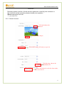
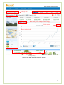
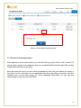
1
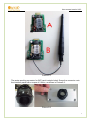
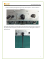
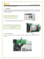
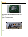
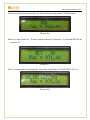
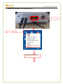
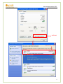
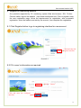
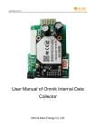
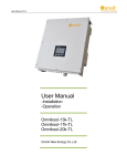
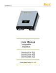
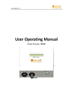
User Manual of Omnik Internal Data Collector Omnik New Energy Co. Ltd. User manual version V2.3 Catalog Part 1. WiFi Card Install SOP.................................................................................................................................. 3 1. Disassembly....................................................................................................................................................... 3 2. Preparation......................................................................................................................................................... 3 3. Installation .......................................................................................................................................................... 5 Part 2. Wifi card user manual .................................................................................................................................. 8 1. Unpacking .......................................................................................................................................................... 8 2. PV data collector interface and buttons ......................................................................................................... 8 3. Set up antenna .................................................................................................................................................. 8 4. S/N Label ............................................................................................................................................................ 9 5. Connect the PV data collector to the inverter (Shown in Pic.5-1) ............................................................. 9 5.1 Connection .................................................................................................................................................. 9 5.2 IP Address Display and settings............................................................................................................... 9 6. LED Indicators ................................................................................................................................................. 12 7. Network Settings (In AP mode by WiFi) ...................................................................................................... 13 8. Troubleshooting............................................................................................................................................... 17 9. Register on monitoring website..................................................................................................................... 18 9.1 Click Register button to go to registering interface for new account ..................................................... 18 9.2 Fill in user’s information as required ........................................................................................................... 18 10. Login the PV monitoring system to manage the power station .............................................................. 21 10.1 “Owner” User Interface .................................................................................................................................. 21 11. IPhone & iPad application.............................................................................................................................. 26 12. Contact ............................................................................................................................................................. 28 2 User manual version V2.3 Part 1. WiFi Card Install SOP 1. Disassembly Picture 1-1 Unscrew the four screws on the interface panel with the screwdriver as shown in Picture1-1 and keep the screws aside. Picture 1-2 Unscrew the two-holed water-proofing connector from the interface panel. The standard connector coming with the inverter is two-holed as shown in Picture1-2, circled in red. 2. Preparation Pick out the antenna and the water-proofing connector from the package and plug the antenna into the socket circled in red in Picture2-1 A, as shown in Picture2-1 B: 3 User manual version V2.3 Picture 2-1 The water-proofing connector for WiFi card is single-holed. Screw the connector onto the interface panel with a torque of 2.0N.m, as shown in Picture2-2: Picture 2-2 4 User manual version V2.3 3. Installation Insert the WiFi card into the socket marked in red rectangular in Picture3-1 A. Gently insert the card until it fully and tightly contacts with the connecting fingers as shown in Picture3-1 B. Picture3-1 Power on the inverter and check if the red LED is lit to indicate the installation is successful, as shown in Picture3-2. If the red LED is not lit, check if the WiFi card is properly connected to the inverter. Picture3-2 Power off the inverter and put the antenna through the water-proofing connector on the interface panel, as shown in Picture3-3: 5 User manual version V2.3 Picture3-3 Screw the interface panel tight onto the inverter with a torque of 1.2N.m as shown in Picture3-4: Picture3-4 Screw the water-proofing connector tight to fixate the antenna with a torque of 1.5N.m in a way that the antenna is properly mounted and can be turned in 360 degrees as shown in below pictures: Picture 3-5 6 User manual version V2.3 Picture 3-6 Picture 3-7 7 User manual version V2.3 Part 2. Wifi card user manual 1. Unpacking After unpacking the box, please check the parts according to the below list. Contact the manufacturer immediately, should you find any damage, missing or wrong model of the device or any parts. No. Name Quantity A PV data collector 1 B WIFI antenna 1 Picture1-1 2. PV data collector interface and buttons B No. A Name 12pin connecting fingers B Reset Button C I-PEX Interface C A picture2 1 3. Set up antenna Picture2-1 Connect the WIFI antenna with the data collector through I-PEX interface as shown in Pic.3-1: Picture.3-1 8 User manual version V2.3 4. S/N Label Picture4-1 5. Connect the PV data collector to the inverter (Shown in Pic.5-1) 5.1 Connection 1. Power off the inverter; 2. Open the RS232/RS485 interface panel; 3. Plug the data collector with antenna onto the inverter through the connecting fingers; 4. Power on the inverter. Note: Due to the shielding of the metal case, please keep the antenna outside of the inverter. Otherwise, the signal of wireless communication will be too weak. Picture 5-1 5.2 IP Address Display and settings 9 User manual version V2.3 Picture. 5-2 Press the function “button” and the display will change to IP address, as shown in picture 5-4 Picture. 5-3 Picture. 5-4 When you see the IP address, Press Function button for 5 seconds,the default value will be Displayed as in picture 5-5 10 User manual version V2.3 Picture. 5-5 Continue to press the function key, you will see the following picture: YES Pac=xxxw Picture. 5-6 When you see Picture 5-6,Press Function button for 5 seconds,you will see SET OK as in picture 5-7 Picture. 5-7 Pic5-7, automatically quit setting after 5 seconds, it will show 10.10.100.254 IP, Pic 5-8 Picture. 5-8 11 User manual version V2.3 6. LED Indicators LINK RUN STATUS picture6 1 LED Name RUN Status Description On/Blinking Module is working Off Module is not working On LINK Blinking Off STATUS Module is successfully connected to the server by WiFi under STA mode The WiFi module is in AP mode In STA mode; No WiFi connection or no connection to the server On Communication with the inverter is working Blinking Communicating with the inverter (transferring data) Off Communication with the inverter is not working 12 User manual version V2.3 7. Network Settings (In AP mode by WiFi) Insert the module, and turn on the DC power,three minutes later enter the next step. Choose “My network place” click right hand 七 13 User manual version V2.3 Left click 选择 WiFi 热点,左键双击 14 User manual version V2.3 Connect successfully Enter 10.10.100.254 in your browser Fill in the user name “admin”and password”admin” Left button “Search” 15 User manual version V2.3 Choose your regional WiFi and click “Apply” If your WiFi has a password, click confirm Do not fill in Fill in the password of your wifi Whether display your password “Disable”or“Enable”, “Enable”suggested Lest button“Apply” Note: this default setting is router DHCP is on, if you can not connect the network, please check if you open the DHCP function. 16 User manual version V2.3 8. Troubleshooting Status Possible Causes LINK STATUS RUN On On Connection is successful Blink Communicating with the ing inverter Off No power connection Solution On/ Blink No need ing On/ Blink On ing No need Check if the connecting fingers are contacting Off Off properly Check if the inverter is working properly Inverter connection is abnormal On/ Blink Off Off ing Blink On Off ing On/ Blink ing Resetting or initializing Check the LEDs again after 1 minutes WiFi connection is not Change the position of the inverter or the successful On/ On Χ Check if the inverter is working properly antenna to get better signal reception Antenna is not properly Check if antenna is connected properly. Screw connected tight if loose Communication with the Check if the connecting fingers are contacting inverter is abnormal properly Connection of the data collector is abnormal Check the setting of AP wireless router Check the WiFi settings Note 1:Χ means status unknown. Note 2:If the device is still not working after above operations in the table, please try resetting the device. If it is still not working after the reset, please contact customer service of the manufacturer. 17 User manual version V2.3 9. Register on monitoring website Our products supported by PV monitoring system Web site browser:IE8,Firefox, Chrome,safari,log into the website http://www.omnikportal.com, Click on register, enter the user registration page, follow the requirements for registration, after successful registration, enter the mailbox and activity the account, then complete the registration. 9.1 Click Register button to go to registering interface for new account Click and enter the register interface Picture 9-1 9.2 Fill in user’s information as required choose“Owner” Click and enter the configure interface 18 User manual version V2.3 Picture 9-2 Remarks: please read the <Omnik service agreement >carefully, the enclosure is the cost list for all the countries, please choose your operators Owner means the final user “*” you must fill it 9.2.1 “Owner” Account Click and choose the aim pic Click”OK”save the pic Fill in WiFi card’s S/N code, see pic 9-4 Click the map, choose the installation site Select, and choose it to be the share mode, other user can see 19 User manual version V2.3 Finish the register Picture 9-3 Picture 9-4 20 User manual version V2.3 10. Login the PV monitoring system to manage the power station After the successful register and account activation,open the login interface as below picture 9-1, input the correct email and code and enter the PV monitoring system, then you can monitor and manage the power station. Input the correct email and code Picture 10-1 10.1 “Owner” User Interface Power station list Picture 10-2 21 User manual version V2.3 Choose your station and enter Edit or delete the case Picture 10-3 List of power Not yet open Back to 9-2 Enter the sharing case Add one case under your account, same as 9-3 Enter the configure “company account” interface Reset password Picture 10-4 navigation bar 22 User manual version V2.3 Change case Case info search Real-time power and generated energy Print current Power station info Energy saving Picture 10-5 Main interface of power station 23 User manual version V2.3 Internal temperature Latest data collecting time Picture 10-6 Real Time Interface Choose the aim inverter Parameter options Picture 10-7 History Interface 24 User manual version V2.3 Click, turn to picture 9-7 Picture 10-8 Alert Interfaces The interface same as picture 9-3 Picture 10-9 System Setting Interface 25 User manual version V2.3 Picture 10-10 System Setting Interface 11. IPhone & iPad application After registration of the power station, you can input the key words: Omnik,solar, inverter, PV, energy ,plant, monitor at the app store, then you can download the Omnik solar (iPhone) and Omnik Solar HD(iPad) at app store. After the download input your user name and password, then visit your station,(we supply a free demo, for the users who do not register)choose the power station and enter the main interface, then you the daily energy etc. will be displayed. Meanwhile, you can view the relevant date to view the curve as below: 26 User manual version V2.3 Picture 10-1 1. Log in interface 2. Power station list interface 3. Main interface 4. Daytime curve interface 27 User manual version V2.3 12. Contact If you have any technical problems about our products,please contact us,you should confirm the follow things before contact us: Device model Data collector serial number The number of connected inverter Add: Xinghu Road No.218 bioBAY Park A4, Suzhou China Zip code:215213 Fax: +86 512 6295 6682 Tel: +86 512 6295 6676 Mail: [email protected] 28