1
Software Development Kit
Reference Manual
Software Version 3.1
Document No. 06-RM-1600 Revision: 2.B
30 September 2010
SDK Reference Manual
Contents overview
Contents overview
This manual consists of two parts: firstly a set of reference chapters for all the tools, followed
by a number of chapters describing the programming languages and file formats. The following is a summary of the contents of each chapter.
Part 1: Tools
1
SDK overview . . . . . . . . . . . . . . . . . . . . . . . . . . . . . . . . . . . . . . . . . . . . . . 12
Gives an overview of the tool chain.
2
Building programs . . . . . . . . . . . . . . . . . . . . . . . . . . . . . . . . . . . . . . . . . . 18
Describes the command-line options and parameters used for compiling and building programs.
3
The preprocessor . . . . . . . . . . . . . . . . . . . . . . . . . . . . . . . . . . . . . . . . . . . 35
Documents the preprocessor, how to invoke it and command-line options.
4
Compiler reference. . . . . . . . . . . . . . . . . . . . . . . . . . . . . . . . . . . . . . . . . . 37
Describes how to invoke the compiler and the command-line options and parameters used
for compiling programs.
5
Macro assembler reference. . . . . . . . . . . . . . . . . . . . . . . . . . . . . . . . . . . 52
Describes how to invoke the assembler and its options and parameters.
6
Linker reference . . . . . . . . . . . . . . . . . . . . . . . . . . . . . . . . . . . . . . . . . . . . 56
Describes how the linker works and how code and data are organized in memory.
7
Debugger reference . . . . . . . . . . . . . . . . . . . . . . . . . . . . . . . . . . . . . . . . . 65
Describes the features and use of the symbolic source code debugger.
8
Simulators reference . . . . . . . . . . . . . . . . . . . . . . . . . . . . . . . . . . . . . . . . 92
Explains how to use the simulator to run programs in the absence of hardware.
9
Archiver. . . . . . . . . . . . . . . . . . . . . . . . . . . . . . . . . . . . . . . . . . . . . . . . . . 100
A utility for creating libraries of object code.
Document No. 06-RM-1600 Revision: 2.B
ClearSpeed Technology Ltd
3
Contents overview
10
SDK Reference Manual
Object file dump . . . . . . . . . . . . . . . . . . . . . . . . . . . . . . . . . . . . . . . . . . . 101
A tool for examining the contents of object files and generating disassembly listings.
Part 2: Programming
11
The Cn language . . . . . . . . . . . . . . . . . . . . . . . . . . . . . . . . . . . . . . . . . . . 105
Describes the main features of the Cn language, focusing on the differences between it and
ANSI standard C. Explains the new parallel data types supported by the compiler and how
they are used in a program.
12
Memory use . . . . . . . . . . . . . . . . . . . . . . . . . . . . . . . . . . . . . . . . . . . . . . 150
This section summarizes the various features of the tool chain related to making efficient use
of code and data memory.
13
Application binary interface . . . . . . . . . . . . . . . . . . . . . . . . . . . . . . . . . 157
A specification of the software interface used between object files compiled with the SDK:
program start-up, how the various data types are stored in memory, and the function calling
and parameter passing conventions.
14
Assembly language . . . . . . . . . . . . . . . . . . . . . . . . . . . . . . . . . . . . . . . . 179
Defines the syntax of the assembly language for CSX processor cores and the directives supported by the assembler.
15
Bibliography . . . . . . . . . . . . . . . . . . . . . . . . . . . . . . . . . . . . . . . . . . . . . . 202
References to sources of further information.
4
Document No. 06-RM-1600 Revision: 2.B
ClearSpeed Technology LtdLtd
SDK Reference Manual
Table of contents
Table of contents
1
2
3
4
SDK overview . . . . . . . . . . . . . . . . . . . . . . . . . . . . . . . . . . . . . . . . . . . . . 12
1.1
A brief description of the software development tools . . . . . . . . . . . . . . . 12
1.2
Command line . . . . . . . . . . . . . . . . . . . . . . . . . . . . . . . . . . . . . . . . . . . . . 13
1.2.1
Syntax . . . . . . . . . . . . . . . . . . . . . . . . . . . . . . . . . . . . . . . . . . . . . . . . . . 13
1.2.2
Options . . . . . . . . . . . . . . . . . . . . . . . . . . . . . . . . . . . . . . . . . . . . . . . . . 14
1.2.3
Generic options . . . . . . . . . . . . . . . . . . . . . . . . . . . . . . . . . . . . . . . . . . . 14
1.3
File naming conventions . . . . . . . . . . . . . . . . . . . . . . . . . . . . . . . . . . . . . . 14
1.4
Libraries . . . . . . . . . . . . . . . . . . . . . . . . . . . . . . . . . . . . . . . . . . . . . . . . . . 15
1.5
Header files . . . . . . . . . . . . . . . . . . . . . . . . . . . . . . . . . . . . . . . . . . . . . . . 15
1.6
Environment variables . . . . . . . . . . . . . . . . . . . . . . . . . . . . . . . . . . . . . . . 15
1.7
Predefined macros . . . . . . . . . . . . . . . . . . . . . . . . . . . . . . . . . . . . . . . . . . 16
1.8
Error reporting . . . . . . . . . . . . . . . . . . . . . . . . . . . . . . . . . . . . . . . . . . . . . 16
1.9
Configuration file . . . . . . . . . . . . . . . . . . . . . . . . . . . . . . . . . . . . . . . . . . . 17
1.10
Licensing and open source components . . . . . . . . . . . . . . . . . . . . . . . . . 17
Building programs . . . . . . . . . . . . . . . . . . . . . . . . . . . . . . . . . . . . . . . . . 18
2.1
Hello world . . . . . . . . . . . . . . . . . . . . . . . . . . . . . . . . . . . . . . . . . . . . . . . . 18
2.2
Multiple source files . . . . . . . . . . . . . . . . . . . . . . . . . . . . . . . . . . . . . . . . . 18
2.3
Processing performed by cscn . . . . . . . . . . . . . . . . . . . . . . . . . . . . . . . . . 19
2.4
Invoking cscn . . . . . . . . . . . . . . . . . . . . . . . . . . . . . . . . . . . . . . . . . . . . . . 20
2.4.1
Generic options . . . . . . . . . . . . . . . . . . . . . . . . . . . . . . . . . . . . . . . . . . . 20
2.4.2
Preprocessor options . . . . . . . . . . . . . . . . . . . . . . . . . . . . . . . . . . . . . . . 20
2.4.3
Compiler options . . . . . . . . . . . . . . . . . . . . . . . . . . . . . . . . . . . . . . . . . . 22
2.4.4
Assembler options . . . . . . . . . . . . . . . . . . . . . . . . . . . . . . . . . . . . . . . . . 27
2.4.5
Linker options . . . . . . . . . . . . . . . . . . . . . . . . . . . . . . . . . . . . . . . . . . . . 28
The preprocessor . . . . . . . . . . . . . . . . . . . . . . . . . . . . . . . . . . . . . . . . . . 35
3.1
Invoking the preprocessor . . . . . . . . . . . . . . . . . . . . . . . . . . . . . . . . . . . . 35
3.2
Command-line options . . . . . . . . . . . . . . . . . . . . . . . . . . . . . . . . . . . . . . . 35
Compiler reference . . . . . . . . . . . . . . . . . . . . . . . . . . . . . . . . . . . . . . . . . 37
4.1
Invoking the compiler . . . . . . . . . . . . . . . . . . . . . . . . . . . . . . . . . . . . . . . . 37
4.2
Command-line options . . . . . . . . . . . . . . . . . . . . . . . . . . . . . . . . . . . . . . . 37
Document No. 06-RM-1600 Revision: 2.B
ClearSpeed Technology Ltd
5
Table of contents
4.3
4.4
SDK Reference Manual
Function inlining . . . . . . . . . . . . . . . . . . . . . . . . . . . . . . . . . . . . . . . . . . . . 41
4.3.1
Conditions on inlining . . . . . . . . . . . . . . . . . . . . . . . . . . . . . . . . . . . . . . . 42
4.3.2
User controls . . . . . . . . . . . . . . . . . . . . . . . . . . . . . . . . . . . . . . . . . . . . . 42
Compiler optimizations . . . . . . . . . . . . . . . . . . . . . . . . . . . . . . . . . . . . . . . 44
4.4.1
Dead object removal . . . . . . . . . . . . . . . . . . . . . . . . . . . . . . . . . . . . . . . 45
4.4.2
Constant evaluation . . . . . . . . . . . . . . . . . . . . . . . . . . . . . . . . . . . . . . . . 45
4.4.3
Switch transformation . . . . . . . . . . . . . . . . . . . . . . . . . . . . . . . . . . . . . . 46
4.4.4
Global register allocation . . . . . . . . . . . . . . . . . . . . . . . . . . . . . . . . . . . . 46
4.4.5
Basic-block ordering . . . . . . . . . . . . . . . . . . . . . . . . . . . . . . . . . . . . . . . 46
4.4.6
Share-string initializers . . . . . . . . . . . . . . . . . . . . . . . . . . . . . . . . . . . . . 46
4.4.7
Dead block removal . . . . . . . . . . . . . . . . . . . . . . . . . . . . . . . . . . . . . . . . 46
4.4.8
Basic-block merging . . . . . . . . . . . . . . . . . . . . . . . . . . . . . . . . . . . . . . . 46
4.4.9
Move post-operator assignments . . . . . . . . . . . . . . . . . . . . . . . . . . . . . 47
4.4.10
Copy propagation . . . . . . . . . . . . . . . . . . . . . . . . . . . . . . . . . . . . . . . . . 47
4.4.11
Strength reduction . . . . . . . . . . . . . . . . . . . . . . . . . . . . . . . . . . . . . . . . . 47
4.4.12
Constant propagation . . . . . . . . . . . . . . . . . . . . . . . . . . . . . . . . . . . . . . 47
4.4.13
Dead code removal . . . . . . . . . . . . . . . . . . . . . . . . . . . . . . . . . . . . . . . . 47
4.4.14
Live range splitting . . . . . . . . . . . . . . . . . . . . . . . . . . . . . . . . . . . . . . . . . 47
4.4.15
Global register preallocation . . . . . . . . . . . . . . . . . . . . . . . . . . . . . . . . . 47
4.4.16
Common subexpression elimination . . . . . . . . . . . . . . . . . . . . . . . . . . . 48
4.4.17
Tail recursion elimination . . . . . . . . . . . . . . . . . . . . . . . . . . . . . . . . . . . . 48
4.4.18
Loop invariant code motion . . . . . . . . . . . . . . . . . . . . . . . . . . . . . . . . . . 48
4.4.19
Tail merging . . . . . . . . . . . . . . . . . . . . . . . . . . . . . . . . . . . . . . . . . . . . . . 48
4.4.20
Algebraic simplification . . . . . . . . . . . . . . . . . . . . . . . . . . . . . . . . . . . . . 48
4.4.21
Chain flow optimization . . . . . . . . . . . . . . . . . . . . . . . . . . . . . . . . . . . . . 49
4.4.22
Peephole optimizer . . . . . . . . . . . . . . . . . . . . . . . . . . . . . . . . . . . . . . . . 49
4.4.23
Scalar replacement . . . . . . . . . . . . . . . . . . . . . . . . . . . . . . . . . . . . . . . . 49
4.4.24
Remove empty loops . . . . . . . . . . . . . . . . . . . . . . . . . . . . . . . . . . . . . . . 49
4.4.25
Loop inversion . . . . . . . . . . . . . . . . . . . . . . . . . . . . . . . . . . . . . . . . . . . . 49
4.4.26
Expression-level scheduler . . . . . . . . . . . . . . . . . . . . . . . . . . . . . . . . . . 49
4.4.27
ld/st offset normalization . . . . . . . . . . . . . . . . . . . . . . . . . . . . . . . . . . . . 49
4.4.28
Instruction-level scheduler . . . . . . . . . . . . . . . . . . . . . . . . . . . . . . . . . . . 50
4.4.29
Loop reversal . . . . . . . . . . . . . . . . . . . . . . . . . . . . . . . . . . . . . . . . . . . . . 50
4.4.30
Loop fusion . . . . . . . . . . . . . . . . . . . . . . . . . . . . . . . . . . . . . . . . . . . . . . 50
4.4.31
Loop scalar replacement . . . . . . . . . . . . . . . . . . . . . . . . . . . . . . . . . . . . 50
4.4.32
Loop strength reduction . . . . . . . . . . . . . . . . . . . . . . . . . . . . . . . . . . . . . 50
4.4.33
Loop induction variable elimination . . . . . . . . . . . . . . . . . . . . . . . . . . . . 51
6
Document No. 06-RM-1600 Revision: 2.B
ClearSpeed Technology Ltd
SDK Reference Manual
4.4.34
5
6
7
Table of contents
Loop unrolling . . . . . . . . . . . . . . . . . . . . . . . . . . . . . . . . . . . . . . . . . . . . 51
Macro assembler reference . . . . . . . . . . . . . . . . . . . . . . . . . . . . . . . . . . 52
5.1
Invoking the assembler . . . . . . . . . . . . . . . . . . . . . . . . . . . . . . . . . . . . . . 52
5.2
Command-line options . . . . . . . . . . . . . . . . . . . . . . . . . . . . . . . . . . . . . . . 52
Linker reference . . . . . . . . . . . . . . . . . . . . . . . . . . . . . . . . . . . . . . . . . . . 56
6.1
Basic terminology and concepts . . . . . . . . . . . . . . . . . . . . . . . . . . . . . . . . 56
6.2
Invoking the linker . . . . . . . . . . . . . . . . . . . . . . . . . . . . . . . . . . . . . . . . . . 56
6.3
Command-line options . . . . . . . . . . . . . . . . . . . . . . . . . . . . . . . . . . . . . . . 56
6.3.1
Category: files and paths . . . . . . . . . . . . . . . . . . . . . . . . . . . . . . . . . . . . 58
6.3.2
Category: file layout . . . . . . . . . . . . . . . . . . . . . . . . . . . . . . . . . . . . . . . . 59
6.3.3
Category: map . . . . . . . . . . . . . . . . . . . . . . . . . . . . . . . . . . . . . . . . . . . . 59
6.3.4
Category: symbols . . . . . . . . . . . . . . . . . . . . . . . . . . . . . . . . . . . . . . . . . 60
6.3.5
Category: other . . . . . . . . . . . . . . . . . . . . . . . . . . . . . . . . . . . . . . . . . . . 61
6.4
File layout . . . . . . . . . . . . . . . . . . . . . . . . . . . . . . . . . . . . . . . . . . . . . . . . . 62
6.5
Order of processing input files . . . . . . . . . . . . . . . . . . . . . . . . . . . . . . . . . 63
6.6
Search paths . . . . . . . . . . . . . . . . . . . . . . . . . . . . . . . . . . . . . . . . . . . . . . 64
6.7
Example . . . . . . . . . . . . . . . . . . . . . . . . . . . . . . . . . . . . . . . . . . . . . . . . . . 64
6.8
Related tools . . . . . . . . . . . . . . . . . . . . . . . . . . . . . . . . . . . . . . . . . . . . . . 64
Debugger reference . . . . . . . . . . . . . . . . . . . . . . . . . . . . . . . . . . . . . . . . 65
7.1
New commands and features . . . . . . . . . . . . . . . . . . . . . . . . . . . . . . . . . . 65
7.2
Invoking the debugger . . . . . . . . . . . . . . . . . . . . . . . . . . . . . . . . . . . . . . . 65
7.3
Using the debugger with a host application . . . . . . . . . . . . . . . . . . . . . . . 65
7.4
7.3.1
Connecting to multiple processors . . . . . . . . . . . . . . . . . . . . . . . . . . . . . 66
7.3.2
Connecting to the processor manually . . . . . . . . . . . . . . . . . . . . . . . . . 67
Commands . . . . . . . . . . . . . . . . . . . . . . . . . . . . . . . . . . . . . . . . . . . . . . . . 67
7.4.1
Connect command and options . . . . . . . . . . . . . . . . . . . . . . . . . . . . . . . 67
7.4.2
Loading code . . . . . . . . . . . . . . . . . . . . . . . . . . . . . . . . . . . . . . . . . . . . . 69
7.4.3
Executing code . . . . . . . . . . . . . . . . . . . . . . . . . . . . . . . . . . . . . . . . . . . 69
7.4.4
Mono debugging . . . . . . . . . . . . . . . . . . . . . . . . . . . . . . . . . . . . . . . . . . 69
7.4.5
Poly debugging . . . . . . . . . . . . . . . . . . . . . . . . . . . . . . . . . . . . . . . . . . . 73
7.4.6
Hardware threads . . . . . . . . . . . . . . . . . . . . . . . . . . . . . . . . . . . . . . . . . 77
7.4.7
System register viewer . . . . . . . . . . . . . . . . . . . . . . . . . . . . . . . . . . . . . 79
7.4.8
TSC semaphore viewer . . . . . . . . . . . . . . . . . . . . . . . . . . . . . . . . . . . . . 83
Document No. 06-RM-1600 Revision: 2.B
ClearSpeed Technology Ltd
7
Table of contents
8
SDK Reference Manual
7.5
Registers . . . . . . . . . . . . . . . . . . . . . . . . . . . . . . . . . . . . . . . . . . . . . . . . . 90
7.6
Using DDD . . . . . . . . . . . . . . . . . . . . . . . . . . . . . . . . . . . . . . . . . . . . . . . . 90
Simulators reference . . . . . . . . . . . . . . . . . . . . . . . . . . . . . . . . . . . . . . . . 92
8.1
Invoking the simulator . . . . . . . . . . . . . . . . . . . . . . . . . . . . . . . . . . . . . . . 92
8.2
Command-line options . . . . . . . . . . . . . . . . . . . . . . . . . . . . . . . . . . . . . . . 92
8.2.1
Command line options for isim . . . . . . . . . . . . . . . . . . . . . . . . . . . . . . . 93
8.2.2
Command line options for casim . . . . . . . . . . . . . . . . . . . . . . . . . . . . . . 94
8.3
Simulating multiple CSX processors . . . . . . . . . . . . . . . . . . . . . . . . . . . . 95
8.4
Errors . . . . . . . . . . . . . . . . . . . . . . . . . . . . . . . . . . . . . . . . . . . . . . . . . . . . 96
8.5
Profiling . . . . . . . . . . . . . . . . . . . . . . . . . . . . . . . . . . . . . . . . . . . . . . . . . . 96
8.5.1
8.6
9
10
11
Profiler trace file production on casim . . . . . . . . . . . . . . . . . . . . . . . . . . 96
Instruction profiling on isim . . . . . . . . . . . . . . . . . . . . . . . . . . . . . . . . . . . . 98
Archiver . . . . . . . . . . . . . . . . . . . . . . . . . . . . . . . . . . . . . . . . . . . . . . . . . 100
9.1
Invoking the archiver . . . . . . . . . . . . . . . . . . . . . . . . . . . . . . . . . . . . . . . 100
9.2
Command-line options . . . . . . . . . . . . . . . . . . . . . . . . . . . . . . . . . . . . . . 100
Object file dump . . . . . . . . . . . . . . . . . . . . . . . . . . . . . . . . . . . . . . . . . . 101
10.1
Invoking csdump . . . . . . . . . . . . . . . . . . . . . . . . . . . . . . . . . . . . . . . . . . 101
10.2
Command-line options . . . . . . . . . . . . . . . . . . . . . . . . . . . . . . . . . . . . . . 101
The Cn language . . . . . . . . . . . . . . . . . . . . . . . . . . . . . . . . . . . . . . . . . . 105
11.1
Summary of differences from ANSI C . . . . . . . . . . . . . . . . . . . . . . . . . . 105
11.2
Glossary of terms . . . . . . . . . . . . . . . . . . . . . . . . . . . . . . . . . . . . . . . . . . 105
11.3
Comments . . . . . . . . . . . . . . . . . . . . . . . . . . . . . . . . . . . . . . . . . . . . . . . 106
11.4
Data types . . . . . . . . . . . . . . . . . . . . . . . . . . . . . . . . . . . . . . . . . . . . . . . 106
11.5
11.4.1
Basic types . . . . . . . . . . . . . . . . . . . . . . . . . . . . . . . . . . . . . . . . . . . . . 106
11.4.2
Derived types . . . . . . . . . . . . . . . . . . . . . . . . . . . . . . . . . . . . . . . . . . . . 106
Mono and poly types . . . . . . . . . . . . . . . . . . . . . . . . . . . . . . . . . . . . . . . 106
11.5.1
Basic types . . . . . . . . . . . . . . . . . . . . . . . . . . . . . . . . . . . . . . . . . . . . . 107
11.5.2
Pointer declaration . . . . . . . . . . . . . . . . . . . . . . . . . . . . . . . . . . . . . . . . 107
11.5.3
Array types . . . . . . . . . . . . . . . . . . . . . . . . . . . . . . . . . . . . . . . . . . . . . . 110
11.5.4
Struct and union types . . . . . . . . . . . . . . . . . . . . . . . . . . . . . . . . . . . . . 110
11.5.5
Typedefs . . . . . . . . . . . . . . . . . . . . . . . . . . . . . . . . . . . . . . . . . . . . . . . 112
8
Document No. 06-RM-1600 Revision: 2.B
ClearSpeed Technology Ltd
SDK Reference Manual
11.6
Assignment . . . . . . . . . . . . . . . . . . . . . . . . . . . . . . . . . . . . . . . . . . . . . . . 112
11.6.1
11.7
11.9
Pointer dereferencing . . . . . . . . . . . . . . . . . . . . . . . . . . . . . . . . . . . . . 113
Expressions . . . . . . . . . . . . . . . . . . . . . . . . . . . . . . . . . . . . . . . . . . . . . . 113
11.7.1
11.8
Table of contents
Casting . . . . . . . . . . . . . . . . . . . . . . . . . . . . . . . . . . . . . . . . . . . . . . . . . 114
Flow Control . . . . . . . . . . . . . . . . . . . . . . . . . . . . . . . . . . . . . . . . . . . . . . 114
11.8.1
Poly flow control . . . . . . . . . . . . . . . . . . . . . . . . . . . . . . . . . . . . . . . . . . 115
11.8.2
If statements . . . . . . . . . . . . . . . . . . . . . . . . . . . . . . . . . . . . . . . . . . . . 115
11.8.3
Switch statements . . . . . . . . . . . . . . . . . . . . . . . . . . . . . . . . . . . . . . . . 118
11.8.4
For, while and do...while loops . . . . . . . . . . . . . . . . . . . . . . . . . . . . . . 119
Functions . . . . . . . . . . . . . . . . . . . . . . . . . . . . . . . . . . . . . . . . . . . . . . . . 124
11.9.1
Function multiplicity . . . . . . . . . . . . . . . . . . . . . . . . . . . . . . . . . . . . . . . 124
11.9.2
Returning from functions . . . . . . . . . . . . . . . . . . . . . . . . . . . . . . . . . . . 124
11.10 Pragmas . . . . . . . . . . . . . . . . . . . . . . . . . . . . . . . . . . . . . . . . . . . . . . . . . 125
11.10.1 Including assembler macros in Cn . . . . . . . . . . . . . . . . . . . . . . . . . . . . . . . . . . . . . . . . 125
11.10.2 Forcing the alignment of identifiers . . . . . . . . . . . . . . . . . . . . . . . . . . . 125
11.10.3 Generating jump tables for switch statements . . . . . . . . . . . . . . . . . . . 125
11.10.4 Unrolling loops . . . . . . . . . . . . . . . . . . . . . . . . . . . . . . . . . . . . . . . . . . . 126
11.10.5 Moving code to on-chip memory . . . . . . . . . . . . . . . . . . . . . . . . . . . . . 126
11.10.6 Setting stack sizes . . . . . . . . . . . . . . . . . . . . . . . . . . . . . . . . . . . . . . . . 127
11.10.7 Controlling inlining functions . . . . . . . . . . . . . . . . . . . . . . . . . . . . . . . . 127
11.11 Inline assembler . . . . . . . . . . . . . . . . . . . . . . . . . . . . . . . . . . . . . . . . . . . 128
11.11.1 Enable state . . . . . . . . . . . . . . . . . . . . . . . . . . . . . . . . . . . . . . . . . . . . . 128
11.11.2 Use of variables within assembler code . . . . . . . . . . . . . . . . . . . . . . . 128
11.11.3 Specifying constraints on register use . . . . . . . . . . . . . . . . . . . . . . . . . 129
11.11.4 Constraint directives . . . . . . . . . . . . . . . . . . . . . . . . . . . . . . . . . . . . . . 131
11.11.5 Inline assembly example . . . . . . . . . . . . . . . . . . . . . . . . . . . . . . . . . . . 137
11.12 Vector intrinsics . . . . . . . . . . . . . . . . . . . . . . . . . . . . . . . . . . . . . . . . . . . 137
11.13 Operator overloading . . . . . . . . . . . . . . . . . . . . . . . . . . . . . . . . . . . . . . . 139
11.14 Supported intrinsics . . . . . . . . . . . . . . . . . . . . . . . . . . . . . . . . . . . . . . . . 141
11.14.1 Arithmetic operations . . . . . . . . . . . . . . . . . . . . . . . . . . . . . . . . . . . . . . 142
11.14.2 Cast operations . . . . . . . . . . . . . . . . . . . . . . . . . . . . . . . . . . . . . . . . . . 143
11.14.3 Reduce operations . . . . . . . . . . . . . . . . . . . . . . . . . . . . . . . . . . . . . . . . 144
11.14.4 Selection operations . . . . . . . . . . . . . . . . . . . . . . . . . . . . . . . . . . . . . . 144
11.14.5 Constructor operations . . . . . . . . . . . . . . . . . . . . . . . . . . . . . . . . . . . . 145
11.15 Reserved keywords . . . . . . . . . . . . . . . . . . . . . . . . . . . . . . . . . . . . . . . . 145
11.16 Supported operators . . . . . . . . . . . . . . . . . . . . . . . . . . . . . . . . . . . . . . . . 146
Document No. 06-RM-1600 Revision: 2.B
ClearSpeed Technology Ltd
9
Table of contents
SDK Reference Manual
11.16.1 Unary operators . . . . . . . . . . . . . . . . . . . . . . . . . . . . . . . . . . . . . . . . . . 146
11.16.2 Binary operators . . . . . . . . . . . . . . . . . . . . . . . . . . . . . . . . . . . . . . . . . 146
11.16.3 Assignment operators . . . . . . . . . . . . . . . . . . . . . . . . . . . . . . . . . . . . . 147
11.16.4 Miscellaneous operators . . . . . . . . . . . . . . . . . . . . . . . . . . . . . . . . . . . 147
11.16.5 Operator precedence . . . . . . . . . . . . . . . . . . . . . . . . . . . . . . . . . . . . . . 148
12
Memory use . . . . . . . . . . . . . . . . . . . . . . . . . . . . . . . . . . . . . . . . . . . . . . 150
12.1
Stack allocation . . . . . . . . . . . . . . . . . . . . . . . . . . . . . . . . . . . . . . . . . . . 150
12.1.1
12.2
Stack checking . . . . . . . . . . . . . . . . . . . . . . . . . . . . . . . . . . . . . . . . . . . . 152
12.2.1
Run-time stack checking . . . . . . . . . . . . . . . . . . . . . . . . . . . . . . . . . . . 152
12.2.2
Stack frame size checking . . . . . . . . . . . . . . . . . . . . . . . . . . . . . . . . . . 152
12.3
Support for ECC memory . . . . . . . . . . . . . . . . . . . . . . . . . . . . . . . . . . . . 152
12.4
Advance card memory map . . . . . . . . . . . . . . . . . . . . . . . . . . . . . . . . . . 153
12.4.1
13
Stack size definition . . . . . . . . . . . . . . . . . . . . . . . . . . . . . . . . . . . . . . . 150
Host memory map . . . . . . . . . . . . . . . . . . . . . . . . . . . . . . . . . . . . . . . . 154
Application binary interface . . . . . . . . . . . . . . . . . . . . . . . . . . . . . . . . . 157
13.1
Overview of the ABI . . . . . . . . . . . . . . . . . . . . . . . . . . . . . . . . . . . . . . . . 157
13.2
Process startup . . . . . . . . . . . . . . . . . . . . . . . . . . . . . . . . . . . . . . . . . . . 157
13.3
13.4
13.2.1
Multithreaded code . . . . . . . . . . . . . . . . . . . . . . . . . . . . . . . . . . . . . . . 158
13.2.2
Program termination . . . . . . . . . . . . . . . . . . . . . . . . . . . . . . . . . . . . . . 158
Data representation and allocation . . . . . . . . . . . . . . . . . . . . . . . . . . . . . 158
13.3.1
Data types . . . . . . . . . . . . . . . . . . . . . . . . . . . . . . . . . . . . . . . . . . . . . . 158
13.3.2
Memory model . . . . . . . . . . . . . . . . . . . . . . . . . . . . . . . . . . . . . . . . . . . 162
13.3.3
Register model . . . . . . . . . . . . . . . . . . . . . . . . . . . . . . . . . . . . . . . . . . . 163
Calling functions . . . . . . . . . . . . . . . . . . . . . . . . . . . . . . . . . . . . . . . . . . . 165
13.4.1
Calling sequence . . . . . . . . . . . . . . . . . . . . . . . . . . . . . . . . . . . . . . . . . 165
13.4.2
Call stack . . . . . . . . . . . . . . . . . . . . . . . . . . . . . . . . . . . . . . . . . . . . . . . 168
13.4.3
Variable allocation and parameter passing . . . . . . . . . . . . . . . . . . . . . 169
13.4.4
Functions with variable number of parameters . . . . . . . . . . . . . . . . . . 170
13.4.5
Status and predicate bits . . . . . . . . . . . . . . . . . . . . . . . . . . . . . . . . . . . 173
13.4.6
Enable state . . . . . . . . . . . . . . . . . . . . . . . . . . . . . . . . . . . . . . . . . . . . . 173
13.5
Poly scratch memory . . . . . . . . . . . . . . . . . . . . . . . . . . . . . . . . . . . . . . . 173
13.6
Semaphores . . . . . . . . . . . . . . . . . . . . . . . . . . . . . . . . . . . . . . . . . . . . . . 174
13.7
Endianness . . . . . . . . . . . . . . . . . . . . . . . . . . . . . . . . . . . . . . . . . . . . . . 175
13.8
Debugging information format . . . . . . . . . . . . . . . . . . . . . . . . . . . . . . . . 176
10
Document No. 06-RM-1600 Revision: 2.B
ClearSpeed Technology Ltd
SDK Reference Manual
14
13.8.1
DWARF extensions . . . . . . . . . . . . . . . . . . . . . . . . . . . . . . . . . . . . . . . 176
13.8.2
DWARF virtual register mapping . . . . . . . . . . . . . . . . . . . . . . . . . . . . . 176
Assembly language . . . . . . . . . . . . . . . . . . . . . . . . . . . . . . . . . . . . . . . . 179
14.1
Overview . . . . . . . . . . . . . . . . . . . . . . . . . . . . . . . . . . . . . . . . . . . . . . . . 179
14.2
Basic syntax . . . . . . . . . . . . . . . . . . . . . . . . . . . . . . . . . . . . . . . . . . . . . . 179
14.3
14.4
14.5
14.2.1
Labels . . . . . . . . . . . . . . . . . . . . . . . . . . . . . . . . . . . . . . . . . . . . . . . . . 179
14.2.2
Instructions . . . . . . . . . . . . . . . . . . . . . . . . . . . . . . . . . . . . . . . . . . . . . 179
14.2.3
Directives . . . . . . . . . . . . . . . . . . . . . . . . . . . . . . . . . . . . . . . . . . . . . . . 180
14.2.4
Comments . . . . . . . . . . . . . . . . . . . . . . . . . . . . . . . . . . . . . . . . . . . . . . 180
14.2.5
Literals . . . . . . . . . . . . . . . . . . . . . . . . . . . . . . . . . . . . . . . . . . . . . . . . . 180
Sections and symbols . . . . . . . . . . . . . . . . . . . . . . . . . . . . . . . . . . . . . . 181
14.3.1
Sections . . . . . . . . . . . . . . . . . . . . . . . . . . . . . . . . . . . . . . . . . . . . . . . . 181
14.3.2
Symbols . . . . . . . . . . . . . . . . . . . . . . . . . . . . . . . . . . . . . . . . . . . . . . . . 182
Instructions . . . . . . . . . . . . . . . . . . . . . . . . . . . . . . . . . . . . . . . . . . . . . . . 184
14.4.1
Instruction mnemonics . . . . . . . . . . . . . . . . . . . . . . . . . . . . . . . . . . . . . 185
14.4.2
Operands . . . . . . . . . . . . . . . . . . . . . . . . . . . . . . . . . . . . . . . . . . . . . . . 185
Directives . . . . . . . . . . . . . . . . . . . . . . . . . . . . . . . . . . . . . . . . . . . . . . . . 188
14.5.1
14.6
14.7
15
Table of contents
CFI directives . . . . . . . . . . . . . . . . . . . . . . . . . . . . . . . . . . . . . . . . . . . . 190
Macros . . . . . . . . . . . . . . . . . . . . . . . . . . . . . . . . . . . . . . . . . . . . . . . . . . 192
14.6.1
Matching macros against instructions . . . . . . . . . . . . . . . . . . . . . . . . . 193
14.6.2
Macro body definition . . . . . . . . . . . . . . . . . . . . . . . . . . . . . . . . . . . . . . 195
14.6.3
Standard header files . . . . . . . . . . . . . . . . . . . . . . . . . . . . . . . . . . . . . . 201
Instruction set extension library . . . . . . . . . . . . . . . . . . . . . . . . . . . . . . . 201
Bibliography . . . . . . . . . . . . . . . . . . . . . . . . . . . . . . . . . . . . . . . . . . . . . 202
Document No. 06-RM-1600 Revision: 2.B
ClearSpeed Technology Ltd
11
SDK overview
1
SDK Reference Manual
SDK overview
This manual describes ClearSpeed’s Software Development Kit (SDK) for its CSX processors.
This manual assumes you are already familiar with the CSX processor architecture and programming concepts. An overview of the architecture can be found in the respective Core
Architecture Manual. Programming concepts are described in SDK Introductory Programming
Manual [3] provided with the SDK.
1.1
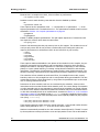
A brief description of the software development tools
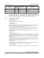
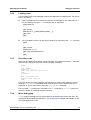
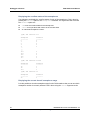
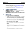
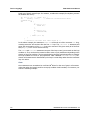
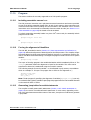
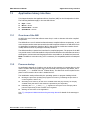
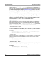
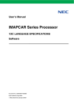
The tool chain contains all the tools necessary to compile, run and debug programs on
ClearSpeed’s simulators and hardware. The main tools used in the tool chain are:
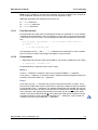
Compiler driver. This controls the following stages of processing:
cscn
cscpp: A standard C macro preprocessor
cncc: Cn language compiler
mass:
Macro assembler
cld
: The object code linker
arcs
Library archive builder.
isim
Functional (instruction set) simulator.
csgdb
Debugger based on GDB.
csdump
This tool converts an object file in to a human readable form, including a
disassembly listing.
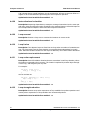
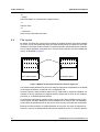
.h
.inc
.cn
Preprocess
cscpp
.i
.cso
Compile
cncc
.is
.s
Archive
arcs
.s
Assemble
mass
.csa
.cso
Link
cld
.csx
Run
csrun
Figure 1.The ClearSpeed software tool chain
12
Document No. 06-RM-1600 Revision: 2.B
ClearSpeed Technology Ltd
SDK Reference Manual
SDK overview
Each of the tools is described in detail in later chapters.
The following tools are also used when running code:
z
csrun : A simple host application program to load the code and provide basic I/O
facilities.
z
csreset : A tool to reset the simulator or hardware to a known state.
These tools are part of the runtime support for the AdvanceTM Accelerator cards and are documented in the CSX600 Runtime Software User Guide [4].
The tools have a standard command line interface and use a common set of command-line
options as well as options specific to each tool. The generic tool options are described in
Section 1.2.3: Generic options on page 14.
All the tools use a configuration file which stores a number of configurable values appropriate
for the target architecture (see Section 1.9: Configuration file on page 17). All of the values
defined in the configuration file can be overridden from the command line to make it easier
to configure individual tools.
Note: There are versions of the SDK tools for Linux and Microsoft Windows. The files are, in
general, compatible between the two and object files compiled on one platform can be used
on the other. Because of the different conventions for marking the end of line, some tools
may have problems with source files copied from other systems. Use your editor or a standard system tool (for example,dos2unix) to convert the files if necessary.
1.2
Command line
The command line for each tool consists of the command name followed by a series of arguments. These arguments can be categorized as operands and options. The operands are typically names of input files. Options provide further control over the behavior of the program.
In general, operands and options can be provided in any order and some options can be
specified multiple times to provide multiple values. The order of some operands and options
is significant as, for example, it may determine the order in which files are processed.
1.2.1
Syntax
The following notation is used to describe the command line arguments:
filename
an argument which is to be substituted with a value is shown in italics
true | false
a choice of literal values for an argument
[option]
an optional argument is shown in brackets
[option]*
an optional argument that can be repeated zero or more times
[,argument]*
an optional argument that can be repeated zero or more times
separated by commas
Any other characters, such as ‘=’, appear literally in the argument.
Document No. 06-RM-1600 Revision: 2.B
ClearSpeed Technology Ltd
13
SDK overview
1.2.2
SDK Reference Manual
Options
Command-line options are used to control the behavior of the tools. There are a set of
generic options and options specific to each tool.
Many of the options have both long and short forms. The short forms are usually a single
character. The long forms are prefixed by a double dash, --, and the short forms by a single
dash, -. The long and short forms are otherwise identical in their use and function.
Some options require a following argument as a value for that option. For example, the
--output option is followed by the file name to be used for the output from the command.
Command-line options which are unrecognized are ignored and a suitable warning is printed.
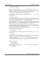
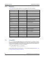
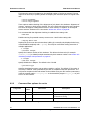
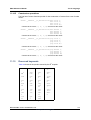
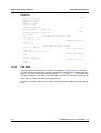
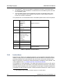
1.2.3
Generic options
These are options which are not specific to a specific tool. These options are shown in
Table 1.
Long name
Short name
Valid values
Description
Displays a list of command options and exits.
--help
-h
--output
-o
--verbose
-v
Switches on verbose output.
--version
-V
Outputs version information for a utility and exits.
filename
Specifies the output file name.
Table 1. Generic command-line options
Command-line options for each tool are described in the appropriate chapter.
1.3
File naming conventions
A number of standard file name extensions are used by convention throughout the tool chain,
as follows:
.cn
Cn language source file
.h
Cn include file
.csi
Preprocessed Cn source file
.is
Assembler source file
.inc
Assembler include file
.s
Preprocessed assembler source
.cso
Object file
.csa
Library file
.csx
Executable file
14
Document No. 06-RM-1600 Revision: 2.B
ClearSpeed Technology Ltd
SDK Reference Manual
1.4
SDK overview
Libraries
The SDK includes most of the standard C libraries. Some functions, such as file I/O, which
are not appropriate for an embedded co-processor core may not be supported on all architectures.
Most of the library functions will be provided as both mono and poly variants.
The default search path for libraries is specified by the CSLIB environment variable.
1.5
Header files
The reference manual for the libraries is provided as a separate document The Cn Standard
Library Reference Manual [2].
A set of standard header files are provided with the libraries. These define the function prototypes for the standard (mono) and poly variants of the library functions, and some other
macro definitions relevant to the ClearSpeed SDK.
The default search path for Cn and assembler header files is specified by the CSINC environment variable.
1.6
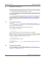
Environment variables
The toolchain uses a number of environment variables to specify various parameters such as
the search paths for various files. These are listed in Table 2.
Environment variable
Description
CSINC
The default search path for included header files.
CSLIB
The default search path for library (.csa) files.
CSPATH
The default search path for executable, configuration and instruction
set files.
CLEARSP_LICENSE_FILE The path to FLEXlm license file. This can be a license-file list,
separated by ‘:’ on Linux and ‘;’ on Microsoft Windows operating
systems.
This can also be port@host where port and host are the
TCP/IP port number and host name from the license file SERVER
line. The port can be omitted if a port in the default range (27000
to 27009) is used.
See the FLEXlm user manual for more details.
Table 2. Toolset environment variables
Document No. 06-RM-1600 Revision: 2.B
ClearSpeed Technology Ltd
15
SDK overview
1.7
SDK Reference Manual
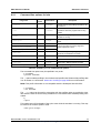
Predefined macros
The macros listed in Table 3 are automatically defined when compiling Cn code.
Environment variable
Description
__ASM__
Defined with the value 1 if the source file is assembler code.
Otherwise undefined.
__BIG_ENDIAN__
Defined with the value 1 if the target processor is big endian.
Otherwise undefined.
__CSCN_VERSION__
Defines the current version of the SDK tool-chain.
The date of compilation as a string literal in the form "Mmm dd
__DATE__
yyyy".
__DEBUG__
Set to 1 if the -g option was used. Otherwise set to 0.
__ELF__
Set to 1 to indicate that ELF object file format will be generated.
__FILE__
A string literal representing the name of the file being compiled.
__LINE__
The current line number as a decimal constant.
__LITTLE_ENDIAN__
Defined with the value 1 if the target processor is little endian.
Otherwise undefined.
__OPT_LEVEL__
Indicates the optimization level specified with the -On options, n
ranges from 0 to 4.
__NUM_PES__
Defined to the number of configured PEs.
__PREPROCESS_ONLY__
Defined with the value 1 if the --preprocess-only option was
specified. Otherwise undefined.
__STDC__
Set to 1 to indicate that standard C is accepted.
__STDCN__
Defined with the value 1 if the source file is Cn code. Otherwise
undefined.
__TIME__
The time of compilation as a string literal in the form "hh:mm:ss".
Table 3. Preprocessor symbols used in the tool chain
1.8
Error reporting
The tools will generate error messages when errors are found in command-line options or
input files.
The tools may also report an internal error which is due to a bug in the tool itself, such as
being unable to handle unexpected input. When such an internal error occurs, please submit
an online report via the ClearSpeed support website:
http://support.clearspeed.com
When submitting a report, you are requested send the output created by the tool, the SDK
version, environment settings and platform on which the error occurred in order to facilitate
ClearSpeed support staff to recreate the problem.
16
Document No. 06-RM-1600 Revision: 2.B
ClearSpeed Technology Ltd
SDK Reference Manual
1.9
SDK overview
Configuration file
All the tools in the SDK make use of a configuration file which holds information about the
target architecture, as well as specific configuration options for each stage of processing. A
configuration file will be provided for each target architecture. The default search path for
configuration files is specified with the CSPATH environment variable. The configuration file
(target_device.cfg) is normally in the config directory of the SDK installation.
The configuration file is split into a number of sections. Sections are organized in a hierarchy
with different levels of the hierarchy delimited by a fullstop in the names of the configuration
parameters. Each section contains parameters relevant to a particular aspect of the target
architecture or part of the tool chain.
1.10
Licensing and open source components
The SDK tools use the FLEXlm license server to manage the software licenses. You will be
provided with a license key for your copy of the SDK. Information for installing FLEXlm and
how to request a license key can be found in the SDK Installation Guide.
Some tools and the standard C libraries are provided under the GNU General Public License
or Lesser General Public License: see the files GPL.html and LGPL.html in the SDK documentation directory for details. The source code for these components is provided as part of
the SDK installation.
Document No. 06-RM-1600 Revision: 2.B
ClearSpeed Technology Ltd
17
Building programs
2
SDK Reference Manual
Building programs
This chapter describes how to use the cscn command to compile a Cn source code file into
an executable file for ClearSpeed’s CSX processors.
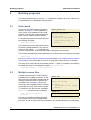
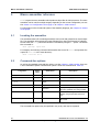
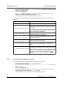
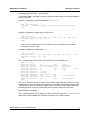
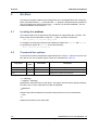
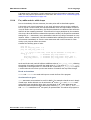
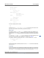
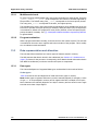
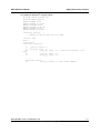
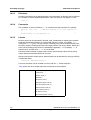
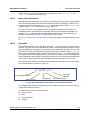
2.1
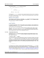
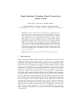
Hello world
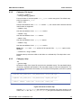
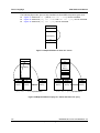
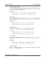
The source of a simple example program is
shown in Example 2.1. This is a parallel (or
poly) version of the traditional “hello world”
program. This will print out the message 96
times, once for each processing element.
To compile the program to an executable, use
the following command:
cscn hello_world.cn
hello_world.cn:
#include <stdiop.h>
#include <lib_ext.h>
int main(void) {
poly int N = get_penum();
}
printfp("Hello %d\n", N);
return 0;
This compiles the source and links the object
Example 2.1
file with the standard libraries. The output is
written to a file called a.csx, by default. Any
errors in the generation of the executable will be displayed on the terminal.
The resulting executable file can be loaded and run on the processor by using the command:
csrun a.csx
See the [3]: SDK Introductory Programming Manual and the [4]: CSX600 Runtime Software
User Guide, for more information on how to run programs on the processor or simulator.
The name of the output file can be specified with the -o option. For example, the following
command will create an executable file called hello_world.csx.
cscn hello_world.cn -o hello_world.csx
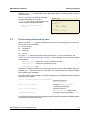
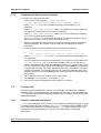
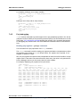
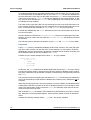
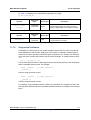
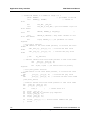
2.2
Multiple source files
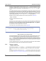
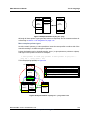
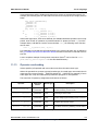
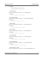
A similar command can be used to build an
executable from multiple source files. In this
case, each source file will be compiled and the
resulting object files linked to generate the
executable code. Example 2.2 shows two
source files which together make up a simple
(nonparallel or mono) “hello world” program.
To compile the two files into the executable
hello.csx, use the following command:
cscn -o hello.csx hello.cn
world.cn
hello.cn:
#include <stdio.h>
extern char *world;
int main() {
printf("Hello %s\n", world);
return 0;
}
world.cn:
char * world = "world!";
Example 2.2
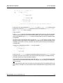
This can be extended to building programs
from multiple source files, including assembler code, as well as object code files and libraries (the standard libraries are included auto-
18
Document No. 06-RM-1600 Revision: 2.B
ClearSpeed Technology Ltd
SDK Reference Manual
Building programs
matically). The cscn command will do the appropriate thing for each file, based on the file
name extension.
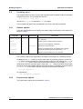
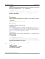
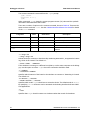
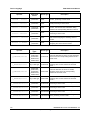
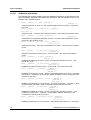
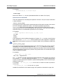
The file in Example 2.3 shows an assembly
language equivalent of the code in
world.cn. This can be used to build an executable with the following command:
cscn -o hello.csx hello.cn
world.is
world.is:
.section
.align
world::
.int
.global
.LL_1::
.asciz
.mono.data
4
.LL_1
world
"world!
Example 2.3
2.3
Processing performed by cscn
When you invoke cscn, it performs the following series of processing steps to convert the
source code to an executable:
z
Preprocessing
z
Compilation
z
Assembly
z
Linking
The steps cscn performs are based on the file extension. For more information, see
Section 1.3: File naming conventions on page 14. Some examples of the processing stages
are as follows:
cscn file.cn
– preprocess, compile, assemble and link
cscn file.is
– preprocess, assemble and link
cscn file.cso – link
Options are available to allow you to stop this process at any of the intermediate steps. For
example, the -c option says not to run the linker. The output in this case consists of object
files created by the assembler.
The “hello world” code, Example 2.1, could be compiled to an executable with the following
sequence of commands:
cscn -E -o hello_world.csi hello_world.cn preprocess source to
hello_world.cn
cscn -S hello_world.csi
compile to hello_world.is
(assembly language file)
cscn -c hello_world.is
assemble source to
hello_world.cso (object code)
cscn hello_world.cso
link object code to executable, a.csx
The following sections provide more details of all the command-line options available and the
processing performed at each step.
Document No. 06-RM-1600 Revision: 2.B
ClearSpeed Technology Ltd
19
Building programs
2.4
SDK Reference Manual
Invoking cscn
The compiler takes a number of source and object files and, by default, builds an executable
program from them. The command line format is:
cscn [option]* [file_name]*
At least one file_name is required for cscn to compile.
The command-line options may be specified in any order, and may be repeated.
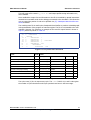
2.4.1
Generic options
These are options which are not specific to a specific stage of processing. These options are
shown in Table 4.
Long name
Short name
Valid values
Description
Redirect the standard output from cncc to the file
cncc_stdout.txt
--cncc_stdout
--help
-h
Displays a list of command options and exits.
--nothing
-n
Does not run the underlying commands
--output
-o
--verbose
-v
Switches on verbose output. This displays the individual
commands and their arguments executed by cscn.
--version
-V
Outputs version information for cscn and exits.
filename
Specifies the output file name.
Table 4. Generic command-line options
The remaining options are organized by the stage of processing in the following sections.
In addition to the cscn options to control each stage of processing, there are a series of
cscn options to pass command line options directly to each tool. For example, the -Wcn or
--cncc-options option can be used to pass options directly to the compiler, cncc. To
allow these options to pass both options (with their - or -- prefix) and values to the underlying tools, the syntax is slightly different from other options. For example, to pass the option
“-e newstart” to the linker using this method, the command line would be:
cscn -Wl,-e=newstart
Or, equivalently:
cscn -cld-options -e=newstart
2.4.2
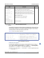
Preprocessor options
The preprocessor options are summarized in Table 5.
20
Document No. 06-RM-1600 Revision: 2.B
ClearSpeed Technology Ltd
SDK Reference Manual
Long name
Building programs
Short
name
Valid values
Description
--define
-D
name[=value]
Define name when preprocessing input.
--inc-dir
-I
path
Add path to the include file search path.
Disallow C++ style line comments.
--no-cpp-comments
--no-lines
-P
Do not produce #line information in
preprocessed output.
--preprocess-only
-E
Preprocess only: do not compile.
Halts after preprocessing with comments
left in the output.
--preprocess-only-comments -C
--preprocess-options
-Wp
[,option[=value]]*
Comma separated list of options to be
passed directly through to preprocessor.
--un-define
-U
name
Undefine a predefined symbol
Table 5. Summary of preprocessor command-line options
-Dname[=value]
--define name[=value]
These options define a preprocessor macro called name. The value is optional and defaults
to 1 if omitted. The option can be used multiple times to define more than one macro.
The following example defines macros TRUE and FALSE with the values 1 and 0 respectively:
-DTRUE -DFALSE=0
--define TRUE --define FALSE=0
-Ipath
--inc-dir path
Adds path to the list of directories to be searched for include files. The default list is specified by the CSINC environment variable. Multiple directories may be specified by using the
option multiple times. The directories will be searched in the order specified.
The following example appends /local/includes to the CSINC include path:
-I/local/includes
--inc-dir /local/includes
--no-cpp-comments
By default, the preprocessor will accept both traditional C block comments (/* ... */) and
C++ line comments (//...). This option disables the use of C++ style comments.
-P
--no-lines
The preprocessor normally inserts lines in the output file of the form:
# linenumber filename flags
This indicates that the output came from line linenumber in file filename. The file name
is followed by zero or more flags separated by spaces. The flags have the meanings shown
in Table 6.
Document No. 06-RM-1600 Revision: 2.B
ClearSpeed Technology Ltd
21
Building programs
SDK Reference Manual
Flag
Meaning
1
This indicates the start of a new file.
2
This indicates returning to a file (after having included another file).
3
This indicates that the following text comes from a system header
file, so certain warnings should be suppressed.
4
This indicates that the following text should be treated as C.
Table 6. Line information flags
The -P / --no-lines option can be used to suppress the generation of this line information. This may be useful if the preprocessor is used to process something other than source
files.
-E
--preprocess-only
Preprocesses only. This halts after the preprocessing stage. The preprocessed output from a
.cn file (Cn source) is written to the standard output, unless it is redirected to a file using
the -o option.
-Uname
--un-define name
These options remove the definition of a macro defined on the command line with -D or predefined by the driver. The set of predefined macros is shown Table 3 on page 16. For example, using
-Wp,option[=value][,option[=value]]*
--preprocess-options [,option[=value]]*
passes options directly through to preprocessor.
Where: option means the option preceded by one or two dashes as appropriate. Options
with parameters must be followed by the symbol “=” and then the value to be passed to the
preprocessor.
For example, to pass the option -Wall (enable all warnings) directly to the preprocessor,
use the option:
-Wp,-Wall
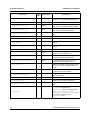
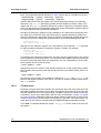
2.4.3
Compiler options
These options are summarized in Table 7.
22
Document No. 06-RM-1600 Revision: 2.B
ClearSpeed Technology Ltd
SDK Reference Manual
Building programs
Short
name
Long name
Valid values
Description
--check-mono-frame-size
integer
Set maximum size (in bytes) of the
mono stack frame for all functions
(default 64 KB).
--check-poly-frame-size
integer
Set maximum size (in bytes) of the
poly stack frame for all functions
(default 3 KB).
Comma separated list of options to
[,option[=value]]* be passed directly through to the
compiler.
--cncc-options
-Wcn
--compile-only
-S
Halts after compile stage.
--debug
-g
Generate debug information.
--dynamic-stack-check
Enables run-time stack checking at
function entry.
--error-mono-frame
Issue error when mono frame
checks fail.
--error-poly-frame
Issue error when poly frame checks
fail.
integer
--force-mono-align
Force alignment of mono data.
--inliner-info
Output information about function
inlining progress
--inliner-disable
Completely switch off function
inlining
--inliner-poly_local_size
integer
--inliner-mono_local_size
integer
--inliner-max_statements
integer
Maximum size of poly locals in any
function to be inlined in bytes
(default: 512)
Maximum size of mono locals in any
function to be inlined in bytes
(default: 1024)
Maximum size of functions to be
inlined counted by statement
(default: 50)
--inliner-auto
Enable the compiler to automatically
choose functions to be inlined
(default at O3 and above)
--inliner-noauto
Prevent the compiler from
automatically choosing functions to
be inlined
--no-check-ldst-offsets
Disable compile-time checks on
stack-pointer-relative loads/stores.
--check-mono-frame
Enable mono stack frame size
checks.
Table 7. Summary of compiler command-line options
Document No. 06-RM-1600 Revision: 2.B
ClearSpeed Technology Ltd
23
Building programs
Long name
SDK Reference Manual
Short
name
Valid values
Description
--check-poly-frame
Enable poly stack frame size
checks.
--no-dynamic-stack-check
Disables run-time stack checking at
function entry.
--nopeephole
Disables peephole optimizations.
--no-poly-ecc
Disables support for poly ECC
memory.
--no-relative-branches
Stops the compiler emitting relative
branch instructions.
--optimize-level-On
Set optimization level n (default 1).
-On
--peephole
Enables peephole optimizations.
--sched
Enable both the expression-level
and instruction-level schedulers.
--nosched
Disable both the expression-level
and instruction-level schedulers.
--presched
Enable the expression-level
scheduler.
--nopresched
Disable the expression-level
scheduler.
--postsched
Enable the instruction-level
scheduler.
--nopostsched
Disable the instruction-level
scheduler.
--set-mono-stack-size-thread-n
--set-poly-stack-size-thread-n
Set the stack sizes (in bytes) for
thread n.
integer
Remove comments from inline
assembly sections in the assembly
output.
--strip-asm-comments
--warning-level
-W
ansi|all|strict
Warning level.
Table 7. Summary of compiler command-line options (Continued)
--check-mono-frame-size integer
--check-poly-frame-size integer
The compiler can check that the mono and poly stack frames used by any function do not
exceed a certain size. These options set the upper limit (in bytes) for the mono and poly stack
frames. The defaults are 64 KB for mono and 3 KB for poly.
-S
--compile-only
24
Document No. 06-RM-1600 Revision: 2.B
ClearSpeed Technology Ltd
SDK Reference Manual
Building programs
Preprocesses and compiles only. This halts after the compilation stage. The output is the
assembler source code for the compiled code. The assembler code output is written to a file
with the extension .is. The default file name can be changed with the -o option.
-Wcn,option[=value][,option[=value]]*
--cncc-options [,option[=value]]*
Passes options directly through to the compiler. Options with parameters must be followed
by the symbol "=" and then the value to be passed to the compiler.
Where: option means the option preceded by one or two dashes as appropriate.
-g
--debug
Causes the compiler and the assembler to include debugging information in the object files.
The debugging information is in DWARF 2.0 format (see Section 13.8: Debugging information format on page 176 for more information). The -g option can be used with optimized
code although this may produce some unexpected results: some variables may not exist, the
flow of control may be different from expected, some statements may have moved or may
never be executed and so on.
--dynamic-stack-check
Enables run time checking of stack usage on function entry. This adds code to each function
to test that the calculated stack usage of the function does not overrun the available stack
space. If the stack usage is calculated to cause a stack overflow, then a warning message
will will be issued by the runtime.
This will cause some performance impact and so is not enabled by default.
--error-mono-frame
--error-poly-frame
By default, the compiler issues a warning if the stack frame exceeds the specified maximum
size. These options causes the compiler to treat this as an error. The maximum stack frame
size can be set with the check-mono-frame-size and check-mono-frame-size
options.
--force-mono-align integer
Causes the compiler to force the alignment of all mono data to the specified alignment. You
can override this option with the use of specific alignment pragmas, See Section 11.10: Pragmas on page 125.
--no-check-ldst-offsets
Disables internal checks on stack-pointer-relative loads and stores.
The compiler normally performs compile-time checks on these instructions to try and detect
if you are likely to run off the end of the allocated space within a function.
Since this has no performance penalty, being compile-time rather than runtime checking, it
is always enabled by default.
--check-mono-frame
--check-poly-frame
Enables the compile-time stack frame checks. If a function’s stack frame exceeds the specified limit, then a warning message will be displayed.
Document No. 06-RM-1600 Revision: 2.B
ClearSpeed Technology Ltd
25
Building programs
SDK Reference Manual
Because this is a compile-time check, it has no effect on performance.
--no-dynamic-stack-check
Disables run-time stack checking. Note that this check is disabled by default.
-On
--optimize-level-On
These options set the optimization level. -O0 corresponds to no optimization. -O4 is the
highest optimization level. The default level is 1. The optimizations enabled at each level are
described in Section 4.4: Compiler optimizations on page 44.
--peephole
--nopeephole
Enable or disable peephole optimizations. This will replace sequences of instructions with
less-expensive versions which have the same effect.
--no-poly-ecc
Produce code assuming that the poly memory has no ECC support. This enables the use of
one-byte poly stores with do not perform a read-modify-write. Setting this option can
improve performance on architectures which do not have ECC on poly memory.
--sched
--nosched
--presched
--nopresched
--postsched
--nopostsched
These options enable and disable the two phases of the scheduler in the compiler; the prescheduler (expression-level scheduler) and post-scheduler (instruction-level scheduler).
Attempts are made to rearrange expressions or instructions (depending on the scheduler
phase) to a more optimal ordering, increasing overlap between load/store and compute
instructions. The latencies of instructions are used to find the most optimal sequence. The
allowed reordering is determined by the dependencies between statements or instructions.
The scheduler will not schedule around control-flow, for example function calls, returns,
branches, and so on. Only straight-line code in a single basic-block gets scheduled. This also
means that the larger a single basic block is, the greater the possibilities open to the scheduler for moving instructions around.
Instructions in inline assembly code are not reordered by the scheduler, however other
instructions can be moved around the inline assembly code. The correct setting of constraints
on inline assembly code is very important to ensure that the scheduler has enough information about a block. Without sufficient information the scheduler may move instructions before
or after inline assembly blocks in an invalid manner. As stated in Section 11.11.4: Constraint
directives on page 131, the default is that a .barrier constraint is applied so that nothing
is allowed to move across an inline assembly block unless explicitly enabled by the programmer (using .nobarrier).
--set-mono-stack-size-thread-n size
--set-poly-stack-size-thread-n size
These options specify the stack size to be used by a thread: n is the thread number that the
stack is being defined for and size is the size of the stack in bytes.
Stacks are automatically created for the main execution thread (thread 0). Thread 7 is used
by the asynchronous memcpy functions: mono and poly stacks of zero size are allocated for
26
Document No. 06-RM-1600 Revision: 2.B
ClearSpeed Technology Ltd
SDK Reference Manual
Building programs
this thread. If you use any other threads in your program then you must allocate mono and
poly stacks for each thread. See Section 12.1: Stack allocation on page 150 for more information.
--strip-asm-comments
Removes comments from inline assembly sections in the assembly output.
-W ansi | strict | all
--warning-level ansi | strict | all
This option controls the types of warning messages generated by the compiler. The default
is a low level of warnings that includes most, but not all, of the ANSI C warnings. Extra warnings can be enabled as shown in Table 8.
Level
Warnings enabled
ansi
Enables generation of ANSI C warnings.
strict
Enables generation of strict warnings.
all
Enables generation of both ANSI and strict warnings.
Table 8. Compiler warning levels
2.4.4
Assembler options
These options are summarized in Table 9.
Long name
Short
name
Valid values
Description
--compile-assemble-only
-c
Halts after the assembly stage.
--debug
-g
Generates debugging information.
--mist-file
-m
Specifies a file containing extra
instruction definitions. May be
specified more than once.
--mass-options
-Wa
[,option[=val
ue]]*
Comma separated list of options to
be passed directly through to the
assembler.
Table 9. Summary of assembler command-line options
-c
--compile-assemble-only
Preprocesses, compiles and assembles only. This halts after the assembly stage. The output
is an object file ready for linking. The object code output is written to a file with the extension
.cso. The default file name can be changed with the -o option.
-g
--debug
Makes the compiler and the assembler include debugging information in the object files. The
debugging information is in DWARF 2.0 format (see Section 13.8: Debugging information
format on page 176 for more information). The -g option can be used with optimized code
although this may produce some unexpected results: some variables may not exist, the flow
Document No. 06-RM-1600 Revision: 2.B
ClearSpeed Technology Ltd
27
Building programs
SDK Reference Manual
of control may be different from expected, some statements may have moved or may never
be executed and so on.
-m file_name
--mist-file file_name
The assembler uses a macro language to define the instruction set. The standard instruction
set definition file is called iset.mst. This option can be used to extend the instruction set
by specifying a file containing further instruction definitions.
-Wa,option[=value][,option[=value]]*
--mass-options [,option[=value]]*
Passes options directly through to the assembler. Options with parameters must be followed
by the symbol “=” and then the value to be passed to the assembler.
Where: option means the option preceded by one or two dashes as appropriate.
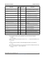
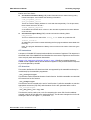
2.4.5
Linker options
The options which control linking are summarized in Table 10.
Long name
Short
name
Valid values
Create a cross reference table.
--creff
--cld-options
-Wl,
--defsym
--discard-all
Description
[,option[=value]]*
Comma separated list of options to be
passed directly through to the linker.
symbol=value
Define the value of a symbol.
Discard all local symbols.
-x
Link the executable for dynamic loading.
--dynamic
--entry
-e
symbol
Specifies the symbol that should be used
as an entry point for the executable.
--library
-l
lib_name
Specify an input library.
--library-path
-L
directory
Add to library search path.
filename
Create a map and write it to a file.
--Map
--nostdlibpath
Do not search for libraries in standard
library paths.
--nostdlibs
Suppress the inclusion of standard
libraries.
--nostdsymbols
Do not force resolution of standard
symbols.
--Pbss
address
Start address of the poly bss section.
--Pdata
address
Start address of the poly data section.
--print-map
-M
Create a map of the object file.
--relocatable
-r
Include relocation info in the output file.
Table 10. Summary of linker command-line options
28
Document No. 06-RM-1600 Revision: 2.B
ClearSpeed Technology Ltd
SDK Reference Manual
Long name
Building programs
Short
name
Valid values
--restrict
chip-index
Description
Restrict the memory available to the
linker to that associated with a specified
chip.
Lays out the memory for the CSX
statically using a linker script present in
the path.
--static
--strip-all
-s
Do not include the symbol table in the
output file.
--strip-debug
-d
Do not include the debug info in the
output file.
--Tbss
address
Start address of the mono bss section.
--Tdata
address
Start address of the mono data section.
symbol_name
Print references to the given symbol.
address
Start address of the text section.
--trace-symbol
-y
--Ttext
Allows the user to link statically using a
hand crafted linker script file(a)
--use-script [filename]
Table 10. Summary of linker command-line options (Continued)
a. The linker script is straight forward and is similar to ld linker scripts for memory layout.
They each have the form:
MEMORY
{
monodram : ORIGIN = 0x80000000, LENGTH = 512M
monosram : ORIGIN = 0x02000000, LENGTH = 128K
polyram : ORIGIN = 0x0, LENGTH = 6K
noload : ORIGIN = 0x0, LENGTH = 512M
}
with the sizes filled in correctly for the different ranges.
-Wl,option[=value][,option[=value]]*
--cld-options [,option[=value]]*
Passes options directly through to linker. Options with parameters must be followed by the
symbol “=” and then the value to be passed to the linker.
Where: option means the option preceded by one or two dashes as appropriate.
Category: files and paths
-llibrary
--library library
Defines an input library file name. By convention, the linker converts the library name specified into a file name by prepending lib to the name and appending the file extension .csa.
This file name is then looked for in the library search path. The default search path is the
current directory and any paths specified in the CSLIB environment variable.
Document No. 06-RM-1600 Revision: 2.B
ClearSpeed Technology Ltd
29
Building programs
SDK Reference Manual
For example, the command:
cscn hello.cn -lworld
will look for a library file called libworld.csa in the standard library search path.
Note: It is also possible to specify the full library name as an argument as if it were a regular
object file. In this case, the library search is limited to the current directory.
This options can be used multiple times to link multiple libraries.
Some libraries are included automatically (see the description of the --nostdlibs option
below for details).
-Ldir
--library-path dir
Adds a directory to the library search path. This option can be used multiple times to add
more than one directory to the search path. The default library search path is the current
directory and any paths specified in the CSLIB environment variable.
Libraries specified with the -l option will be searched for in the default path and then the
paths specified with the -L option. The search will commence with the current directory and
continue in the order in which the directories appear on the command line.
To support differing conventions on different operating systems, both forward and back
slashes are supported as directory separators in the path. The path can finish with a trailing
slash. If this slash is omitted, one is appended to the path.
For example, the following command will search for the library libworld.csa in the standard search path and in the directory libs:
cscn hello.cn -lworld -Llibs
--nostdlibpath
Forces the linker to ignore the default library search paths specified in the CSLIB environment variable.
--nostdlibs
Suppresses the inclusion of standard libraries. The libraries to be automatically scanned for
symbols by the linker can be specified in the SDK configuration file.
The standard libraries are cn, cn_poly, and cn_ext. This option ignores those libraries
unless they are explicitly named with the -l option as shown in the example below.
cscn --nostdlibs -lcn -lcn_poly -lcn_ext hello.cn
Category: file layout
-e entry_symbol
--entry entry_symbol
Forces the linker to use the symbol entry_symbol as the entry point. The default entry
point for programs is _start.
--Pbss address
30
Document No. 06-RM-1600 Revision: 2.B
ClearSpeed Technology Ltd
SDK Reference Manual
Building programs
Sets the start address of the .poly.bss section. address is a numeric value. Both decimal
and hexadecimal formats are supported. A hexadecimal value is specified using C syntax.
--Pbss 0x1000
--Pdata address
Sets the start address of the .poly.data section. address is a numeric value. Both decimal and hexadecimal formats are supported. A hexadecimal value is specified using C syntax.
--Pdata 0x800
--restrict chip-index
Restricts memory resources visible to the linker to a selected chip. The chip index is zero
based. For example, to restrict the memory resources of a particular CSX executable to the
first chip the following option would be used:
--restrict 0
--Tdata address
Sets the start address of the .mono.data section. address is a numeric value. Both decimal and hexadecimal formats are supported. A hexadecimal value is specified using C syntax.
Document No. 06-RM-1600 Revision: 2.B
ClearSpeed Technology Ltd
31
Building programs
SDK Reference Manual
--Tdata 0x0a000000
--Ttext address
Sets the start address of the .text section. address is a numeric value. Both decimal and
hexadecimal formats are supported. A hexadecimal value is specified using C syntax.
--Ttext 0x80000000
--Tbss address
Sets the start address of the .mono.bss section. address is a numeric value. Both decimal
and hexadecimal formats are supported. A hexadecimal value is specified using C syntax.
--Tbss 0x02000000
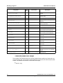
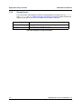
Category: map
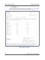
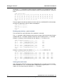
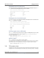
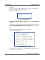
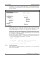
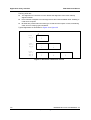
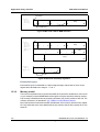
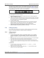
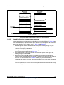
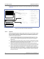
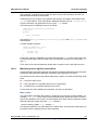
-M
--print-map
Generates a map of the object file and prints it to standard output. The map details layout
of sections, segments and symbols in the executable image as well as the physical file. The
information is presented in two formats: one for sections and segments, and one for symbols,
see Figure 2.
+----------------------------------------------------------------------| Sections: file_offset[size] virt_address[size] section_name type
+----------------------------------------------------------------------| Segments: file_offset[size] virt_address[size] segment_name type
+--------------------------------------------------------------------| Symbols: address
symbol_name
section_name
module_name
Figure 2.Contents of linker map
Here the file_offset[size] pair represents the file location of the given section or segment in the csx file. The virt_address[size] pair gives the location of the section or
segment as it will be loaded in the device memory. The type field says whether the section
or segment is loadable into mono or poly memory space of the device or whether it is purely
data that is stored in the object file. The valid values are: MONO_LOAD, POLY_LOAD and
UNDEF.
The symbol information consists of a relocated address, symbol name, section name in which
the symbol has been defined and the module name which supplied the definition. If the symbol was defined in the user file, the name with extension will be given. If the symbol comes
from the library, the library name without the prefix or a suffix will be printed. For instance,
if the full library name were libdbg.csa, the module_name shown will be dbg.
--Map filename
Generates a map and writes it to a file. The format of the map file is as described above.
32
Document No. 06-RM-1600 Revision: 2.B
ClearSpeed Technology Ltd
SDK Reference Manual
Building programs
Category: symbols
--creff
Generates a cross-reference table. The cross-reference table lists symbols, the definitions of
which have been found, and details all locations where the symbols have been referenced.
By default, the cross-reference table is printed to standard output. If the --Map option is
also specified, the table is appended to the map file.
The format of the cross-reference table is shown in Figure 3.
+----------------------------------------------------------------------| X reference: sym_name in module_name:section_name @ addr_org[relocated]
|
ref_in_module @ addr_org[relocated]
Figure 3.Format of cross-reference table
The first line displays the symbol name, module (file) name, and the section name in which
the symbol was defined. Also, the address pair is given that specifies this location. The
addr_org field is an address relative to the start of the section before relocation (always 0).
The relocated field reflects the actual placement of the sections in the executable image
and is the true address where the symbol can be found in the relevant domain (mono or poly)
of the address space of the device.
This line is followed by zero or more lines, which contain the module name and the address
pair describing the location where the symbol has been referenced.
--defsym name=value
Sets the value of a symbol. name is a string, value an integer given in decimal or hexadecimal format. If the symbol was external, it is redefined to be global. This option can be used
multiple times to define multiple symbols.
--defsym start_address=0x00400000
This defines an absolute symbol. That is, it specifies the final value of the symbol after linking
(see section Section 14.3.2: Symbols for more information about symbol types).
--dynamic
Links the executable for dynamic loading.
--nostdsymbols
It is possible to specify symbols in the configuration file that the linker will treat as external
symbols to be resolved, even if they were never explicitly referenced in the code. This is useful for forcing special libraries, such as the bootstrap or prologue/epilogue code, to be
included with the executable.
This option switches off this default linker behavior.
-r
--relocatable
Makes the output file relocatable. All relocation information will be included in the output file.
-s
--strip-all
Document No. 06-RM-1600 Revision: 2.B
ClearSpeed Technology Ltd
33
Building programs
SDK Reference Manual
Omits all symbol information from the output file.
-d
--strip-debug
Omits debugger symbol information (but not all symbols) from the output file.
-x
--discard-all
Omits all local symbol information from the output file. Similar to -s but global symbols are
left in the output file.
-y symbol_name
--trace-symbol symbol_name
Causes the specified symbol to be traced. Each reference to the chosen symbol will be
reported (together with a module name and local address). This option can be specified multiple times to trace multiple symbols. If the --Map option was specified as well, the symbol
trace information is appended to the map file.
The format in which the information is presented is analogous to the --creff option.
34
Document No. 06-RM-1600 Revision: 2.B
ClearSpeed Technology Ltd
SDK Reference Manual
3
The preprocessor
The preprocessor
This is a port of the GNU C preprocessor, cpp(1) with some modifications to enable it to work
under Microsoft Windows. Because of this, it does not support all the usual ClearSpeed SDK
command-line options.
The preprocessor expands textual macros and strips comments from the source code. In the
ClearSpeed tool chain, the preprocessor can be used with both Cn and assembly source files
so it is provided as a standalone tool.
3.1
Invoking the preprocessor
The preprocessor takes a source file (Cn or assembler) and generates an output file. The output filename will be based on the input file by replacing the extension with .i, unless this
can be overridden with the -o option. The preprocessor command line is:
cscpp [option]* source_file
For example, the following command will preprocess a Cn file, foo.cn, and place the output
in foo.i, in the same directory:
cscpp foo.cn -o foo.i
3.2
Command-line options
Note: cscpp does not use the standard command-line options used by the other SDK tools.
Table 11 shows a list of the most relevant command-line options.
Short
name
Valid values
Description
name[=value]
Sets a preprocessor symbol to be defined or to the given value.
-I
directory
Adds a directory to the path which is searched for include files.
-o
filename
Defines the output filename.
-D
Table 11. Summary of cscpp command-line options
Options may be given in any order and may be repeated.
-D name
Defines the macro name with the string “1” as its definition.
-I directory
Appends a directory to the search path for include files. The directories are searched in the
order specified.
1. Note that this is not the current GNU implementation, because that has been rolled into the
gcc compiler, but an older, stand-alone version. However, cscpp has all the functionality that
is required for its use in the ClearSpeed SDK tool chain.
Document No. 06-RM-1600 Revision: 2.B
ClearSpeed Technology Ltd
35
The preprocessor
SDK Reference Manual
-o filename
Specifies the output file. Conventionally, the suffix .i is used for preprocessed files.
36
Document No. 06-RM-1600 Revision: 2.B
ClearSpeed Technology Ltd
SDK Reference Manual
4
Compiler reference
Compiler reference
The compiler takes a preprocessed source file containing Cn code and generates an output
file containing assembly language source. The compiler expects preprocessed files as input.
A separate tool, called cscpp, is used to preprocess source files, before passing them to the
compiler. This is described in more detail in Chapter 3: The preprocessor. Note that any standard C preprocessor could be used in place of cscpp as long as it emits line directives in the
right form (see Section 14.5: Directives on page 188).
4.1
Invoking the compiler
The compiler takes a preprocessed file, and generates an output file, containing assembly
code, ready to be assembled. The compiler will construct the output filename from the input
filename by changing the file extension to .s, unless this has been overridden by using the
-o option. The compiler command is:
cncc [option]* source_file
Assuming you have a preprocessed file called foo.i, the command to compile this into
assembly code is:
cncc foo.i
This will create a file called foo.s located in the same directory as foo.i. To override the
default output file name, use the following command:
cncc foo.i -o bar.s
Where bar.s is the name of the desired output file.
4.2
Command-line options
As well as the common command-line options defined in Chapter 1: SDK overview, the compiler has its own set of specific options. These are summarized in Table 12.
Note: The command line options to cncc are different from the other tools in that all options,
inlcuding long forms, are prefixed by a single dash, ‘-’.
Short
name
Long name
Valid values
Description
name[=value] Define name when preprocessing input.
-D
g
Produce debug information.
I
path
Add path to the include file search path.
o
file
Place the output into file.
Table 12. Summary of cncc command-line options
Document No. 06-RM-1600 Revision: 2.B
ClearSpeed Technology Ltd
37
Compiler reference
Long name
SDK Reference Manual
Short
name
U
Valid values
name
Description
Undefine name when preprocessing input.
Produce code targeted at big-endian target.
-bigendian
-check-mono-frame-size
integer
Set maximum size (in bytes) of the mono
stack frame for all functions (default 64 KB).
-check-poly-frame-size
integer
Set maximum size (in bytes) of the poly stack
frame for all functions (default 3KB).
-dynamic-stack-check
Enables run-time stack checking at function
entry.
-error-mono-frame
Issue error when mono frame checks fail.
-error-poly-frame
Issue error when poly frame checks fail.
-littleendian
Produce code targeted at little-endian target
(default).
-inliner-info
Output information about function inlining
progress
-inliner-disable
Completely switch off function inlining
-inliner-poly_local_size
-inliner-mono_local_size
-inliner-max_statements
integer
integer
integer
Maximum size of poly locals in any function to
be inlined in bytes (default: 512)
Maximum size of mono locals in any function
to be inlined in bytes (default: 1024)
Maximum size of functions to be inlined
counted by statement (default: 50)
-inliner-auto
Enable the compiler to automatically choose
functions to be inlined (default at O3 and
above)
-inliner-noauto
Prevent the compiler from automatically
choosing functions to be inlined
-no-check-ldst-offsets
Disable compile-time checks on stack pointer
relative loads/stores.
-check-mono-frame
Enable mono stack frame size checks.
-check-poly-frame
Enable poly stack frame size checks.
-no-dynamic-stack-check
Disables run-time stack checking at function
entry.
-nopeephole
Disables peephole optimizations.
-nopeephole implies all the
-nopeephole* options to signify that the
-nopeephole-pred-then-jump,
-nopeephole-redundant-compare, and
so on, options are all set when
-nopeephole is set.
Table 12. Summary of cncc command-line options (Continued)
38
Document No. 06-RM-1600 Revision: 2.B
ClearSpeed Technology Ltd
SDK Reference Manual
Compiler reference
Short
name
Long name
Valid values
Description
-nopeephole-redundant-compare
Disables removal of redundant comparisons
with zero following an arithmetic operation.
-nopeephole-pred-then-jump
Disables merging of predicate-movement
instructions with subsequent jump
instructions.
-nopeephole-mono-stack-changes
Disables merging of back-to-back decreases
and increases in the mono stack pointer.
-nopeephole-poly-stack-changes
Disables merging of back-to-back decreases
and increases in the poly stack pointer
-nopeephole-combine-ldst
Disables merging of stack-pointer-relative
loads and stores to the largest possible sizes.
-peephole
Enables peephole optimizations.
-no-poly-ecc
Disables support for poly ECC memory.
-no-relative-branches
Stops the compiler emitting relative branch
instructions.
-set-mono-stack-size-thread-n
-set-poly-stack-size-thread-n
integer
Set the stack sizes (in bytes) for thread n.
-sched
Enable both the expression-level and
instruction-level schedulers.
-nosched
Disable both the expression-level and
instruction-level schedulers.
-presched
Enable the expression-level scheduler.
-nopresched
Disable the expression-level scheduler.
-postsched
Enable the instruction-level scheduler.
-nopostsched
Disable the instruction-level scheduler.
Table 12. Summary of cncc command-line options (Continued)
The command-line options may be specified in any order, and may be repeated.
-D name
-D name=value
Define name when preprocessing the source file. The value is optional and defaults to zero
if not specified.
-g
This option causes the compiler to include debugging information in the output file.
-I path
Add path to the list of directories to be searched for include files. Multiple directories may
be specified by using the -I option multiple times.
-o file
Document No. 06-RM-1600 Revision: 2.B
ClearSpeed Technology Ltd
39
Compiler reference
SDK Reference Manual
The output file name. If no name is specified, the compiler generates an output
filename from the input file name with the extension .s.
-U name
Undefine name when preprocessing the source file.
-bigendian
Produce code for a big-endian target.
-check-mono-frame-size integer
-check-poly-frame-size integer
The compiler can check that the mono and poly stack frames used by any function do not
exceed a certain size. These options set the upper limit (in bytes) for the mono and poly stack
frames. The defaults are 64 KB for mono and 3 KB for poly.
-dynamic-stack-check
Enables run time checking of stack usage on function entry. This adds code to each function
to test that the calculated stack usage of the function does not overrun the available stack
space. If the stack usage is calculated to cause a stack overflow, then a warning message
will will be issued by the runtime.
This will cause some performance impact and so is not enabled by default.
-error-mono-frame
-error-poly-frame
By default, the compiler issues a warning if the stack frame exceeds the specified maximum
size. These options causes the compiler to treat this as an error. The maximum stack frame
size can be set with the check-mono-frame-size and check-mono-frame-size
options.
-littleendian
Produce code for a little-endian target (default).
-no-check-ldst-offsets
Disables internal checks on stack-pointer-relative loads and stores.
The compiler normally performs compile-time checks on these instructions to try and detect
if you are likely to run off the end of the allocated space within a function.
Since this has no performance penalty, being compile-time rather than runtime checking, it
is always enabled by default.
-check-mono-frame
-check-poly-frame
Enables the compile-time stack frame checks. If a function’s stack frame exceeds the specified limit, then a warning message will be displayed.
Because this is a compile-time check, it has no effect on performance.
-no-dynamic-stack-check
Disables run-time stack checking. Note that this check is disabled by default.
-peephole
-nopeephole
40
Document No. 06-RM-1600 Revision: 2.B
ClearSpeed Technology Ltd
SDK Reference Manual
Compiler reference
Enable or disable peephole optimizations. This will replace sequences of instructions with
less-expensive versions which have the same effect.
-no-poly-ecc
Produce code assuming that the poly memory has no ECC support. This allows using 1-byte
poly stores with no read-modify-write, which are otherwise disallowed when ECC is enabled.
Setting this option can improve performance on architectures where poly memory does not
have ECC enabled.
-set-mono-stack-size-thread-n size
-set-poly-stack-size-thread-n size
These options specify the stack size to be used by a thread: n is the thread number that the
stack is being defined for and size is the size of the stack in bytes.
Stacks are automatically created for the main execution thread (thread 0). Thread 7 is used
by the asynchronous memcpy functions: mono and poly stacks of zero size are allocated for
this thread. If you use any other threads in your program then you must allocate mono and
poly stacks for each thread. See Section 12.1: Stack allocation on page 150 for more information.
-sched
-nosched
-presched
-nopresched
-postsched
-nopostsched
These options enable and disable the two phases of the scheduler in the compiler; the prescheduler (expression-level scheduler) and post-scheduler (instruction-level scheduler).
Attempts are made to rearrange expressions or instructions (depending on the scheduler
phase) to a more optimal ordering, increasing overlap between load/store and compute
instructions. The latencies of instructions are used to find the most optimal sequence. The
allowed reordering is determined by the dependencies between statements or instructions.
The scheduler will not schedule around control-flow, for example function calls, returns,
branches, and so on. Only straight-line code in a single basic-block gets scheduled. This also
means that the larger a single basic block is, the greater the possibilities open to the scheduler for moving instructions around.
Instructions in inline assembly code are not reordered by the scheduler, however other
instructions can be moved around the inline assembly code. The correct setting of constraints
on inline assembly code is very important to ensure that the scheduler has enough information about a block. Without sufficient information the scheduler may move instructions before
or after inline assembly blocks in an invalid manner. As stated in Section 11.11.4: Constraint
directives on page 131, the default is that a .barrier constraint is applied so that nothing
is allowed to move across an inline assembly block unless explicitly enabled by the programmer (using .nobarrier).
4.3
Function inlining
Function inlining is where a function or procedure call statement is replaced by the code that
comprises the body of the called function. This can be done where the code that contains
the function call is compiled in the presence of the definition of the called function. References within the body of the inlined function to the parameters of the function are substituted
Document No. 06-RM-1600 Revision: 2.B
ClearSpeed Technology Ltd
41
Compiler reference
SDK Reference Manual
with the corresponding arguments that were given in the function call. Similarly, return
statements that return a value within the body of the inlined function are replaced by assignments to the object that was assigned to by the original function call statement.
The major benefit of this optimization is to completely eliminate function call overhead and
thereby speed up the execution of the code. Inlining may also allow the compiler to optimize
the code more effectively when the barrier of a function call is removed. Overly aggressive
use of function inlining can, however, result in undesired code bloat and in some circumstances may cause poorer performance by negatively impacting the use of the instruction
cache.
4.3.1
Conditions on inlining
There is a pragma available to force the compiler to always inline a function (see below), but
unless this is used, the compiler always has the option of not inlining a function, whatever
options, pragmas or keywords are specified. The compiler contains rules to determine
whether it makes sense for a function to be inlined. The information about a function that
is taken into account is the size of the function (in terms of the number of statements the
function contains) and the number of local variables the function has, which impacts the
potential register pressure within the calling function as well as the stack usage of the caller.
By default, the compiler will not inline a function that has over 50 statements in its body, or
which has more than 512 bytes of poly local variables, or more than 1024 bytes of mono local
variables. These limits can be changed via the compiler command-line options listed in
Table 13. There are a number of other reasons why a function may not be inlined, these are:
z
Variable argument (varargs) functions
z
Recursive functions
z
Use of computed gotos
If the --inliner-info command line option is given to cscn, the compiler will indicate
the reasons why a function has not been inlined.
The optimization level at which inlining is first enabled is -O0.
Note: Function inlining is enabled at all levels of optimization (including no optimization, O0) in order to allow the consistent compilation of functions that take vector-type arguments
and/or return a vector type. Passing or returning vector types is, at present, not permitted
by the ABI (see Chapter 13: Application binary interface on page 157). The only way such
functions can be used is by forcing inlining of the functions (by using the forceinline pragma).
4.3.2
User controls
As noted above, inlining is an optimization that should be used with care as there is the possibility that it will degrade performance. At levels of optimization below -O3, inlining will
only occur if you indicate that a certain function should be inlined via the use of the inline
keyword or inlining pragmas. At -O3 and above, the compiler will undertake to automatically
inline functions that it evaluates it to be advantageous to do so. The evaluation of the functions to be inlined is based on the above rules.
42
Document No. 06-RM-1600 Revision: 2.B
ClearSpeed Technology Ltd
SDK Reference Manual
Compiler reference
Keywords to control inlining
Use of the ‘inline’ keyword is consistent with the C99 specification. The keyword is placed
on the function declaration as follows:
inline int compute(int x, float y)
{
return x + (int)y;
}
According to C99, such a declaration is only used for inlining; the function will not appear in
its own right in the generated code as an externally visible symbol. If the function is required
to be available to be called against from other compiled modules, the function must be separately declared without the inline keyword, in a different Cn file. It is also possible that
despite the use of the keyword, the function will not be inlined (if the function does not meet
the conditions described above), in which case a separate, noninline, copy of the function
must be available in a compiled module to prevent a build error.
An inline pragma can be used; functions marked with the pragma are not subject to the C99
constraints on inlining.
Compiler options to control inlining
Table 13 shows a set of command-line options for control inlining.
Valid
values
Long name
Description
--inliner-info
Output information about function inlining progress
--inliner-disable
Completely switch off function inlining
Maximum size of poly locals in any function to be inlined in
bytes (default: 512)
--inlinerpoly_local_size
integer
--inlinermono_local_size
integer Maximum size of mono locals in any function to be inlined in
--inlinermax_statements
integer
bytes (default: 1024)
Maximum size of functions to be inlined counted by
statement (default: 50)
--inliner-auto
Enable the compiler to automatically choose functions to be
inlined (default at -O3 and above)
--inliner-noauto
Prevent the compiler from automatically choosing functions
to be inlined
Table 13. Summary of inliner command-line options
Pragmas to control inlining
#pragma inline
This pragma should be placed immediately before the definition of a function. It is a request
for the following function to be inlined, but doesn’t guarantee inlining. The behavior when
marking functions for inlining using this pragma is not the same as when the inline keyword
is used. Using the inline pragma does not affect whether or not a function is generated in
its own right. This does mean, however, that you may need to use the static keyword to
Document No. 06-RM-1600 Revision: 2.B
ClearSpeed Technology Ltd
43
Compiler reference
SDK Reference Manual
avoid multiple symbol definitions where an inline function is defined in a header file and
included in multiple source files within a project.
The inline pragma can be used with on/off placed after it, for example:
#pragma inline on
The effect of this is to mark all functions declared after the pragma with an inline pragma,
until a #pragma inline off is seen.
#pragma inlinecalls
This pragma can be placed before a function call site to indicate that the called function (or
functions) within the succeeding statement should be inlined. This pragma can also be
turned ‘on’ or ‘off’ in the same way as the inline pragma.
#pragma noinline
This pragma can be placed immediately before a function definition and will ensure that the
function is not inlined, even at –O3 and above when auto-inlining is enabled.
#pragma forceinline
This pragma is again placed just before a function definition and indicates that the function
will always be inlined. This overcomes the inlining rules above, except for those rules that
affect functional correctness (varags, recursive functions and computed gotos).
4.4
Compiler optimizations
Table 14 summarizes the optimizations implemented at each level. These are described in
more detail in the following sections.
L
Optimization
Level at which first
enabled
Dead object removal
-O0
Constant evaluation
-O0
Function inlining
-O0
Switch transformation
-O0
Global register allocation
-O1
Basic-block ordering
-O1
Share string initializers
-O1
Dead block removal
-O1
Basic-block merging
-O1
Move post-operator assignments
-O1
Copy propagation
-O1
Strength reduction
-O1
Constant propagation
-O1
Table 14. Summary of optimization levels
44
Document No. 06-RM-1600 Revision: 2.B
ClearSpeed Technology Ltd
SDK Reference Manual
Compiler reference
Optimization
Level at which first
enabled
Dead code removal
-O1
Live range splitting
-O1
Global register pre-allocation
-O1
Common subexpression elimination
-O1
Tail recursion elimination
-O1
Loop invariant code motion
-O1
Tail merging
-O1
Algebraic simplification
-O2
Chain-flow optimization
-O2
Peephole optimizer
-O2
Scalar replacement
-O3
Remove empty loops
-O3
Loop inversion
-O3
Expression-level scheduler
-O3
Ld/st offset normalization
-O3
Instruction-level scheduler
-O3
Loop reversal
-O4
Loop fusion
-O4
Loop scalar replacement
-O4
Loop strength reduction
-O4
Loop induction variable elimination
-O4
Loop unrolling
-O4
Table 14. Summary of optimization levels (Continued)
4.4.1
Dead object removal
Description: Removes objects that are not in use and that cannot be used implicitly from
outside the current compilation unit.
Optimization level at which first enabled: -O0
4.4.2
Constant evaluation
Description: Attempt to replace expressions by simpler or cheaper expressions that have
the same semantics. This is done using constant folding, algebraic identities, tree transformation and canonization of expressions.
Optimization level at which first enabled: -O0
Document No. 06-RM-1600 Revision: 2.B
ClearSpeed Technology Ltd
45
Compiler reference
4.4.3
SDK Reference Manual
Switch transformation
Description: Replace switch statements by jump-tables or if-else chains
Optimization level at which first enabled: -O0
Notes: If-else chains will be produced unless a jump-table pragma is used.
User Controls: A pragma is available to produce a jump-table for any particular switch
statement. To instrument any particular switch, the following text should be added immediately before the switch statement of concern:
#pragma switch jumptable
4.4.4
Global register allocation
Description: Allocate local variables and function parameters to registers where possible.
Optimization level at which first enabled: -O1
4.4.5
Basic-block ordering
Description: Try and place the basic blocks within the current procedure’s control-flow
graph into the most efficient order possible. The engine uses information concerning how
often a block is likely to be used, the probability of taking any particular edge when branching
from the block and the cost of taking branches from the block. The engine reorders
sequences of blocks that have unconditional jumps between them to minimize the number
of unconditional jumps.
Optimization level at which first enabled: -O1
4.4.6
Share-string initializers
Description: Duplicate constant initializers that have equal size and contents are replaced
by a single version.
Optimization level at which first enabled: -O1
4.4.7
Dead block removal
Description: Removal of basic blocks that are not reachable from the procedure entry point.
Optimization level at which first enabled: -O1
4.4.8
Basic-block merging
Description: Merge basic blocks that have a one-to-one flow relation, for example basic
blocks A and B when block B is the only successor of block A and block A is the only predecessor of block B.
Optimization level at which first enabled: -O1
46
Document No. 06-RM-1600 Revision: 2.B
ClearSpeed Technology Ltd
SDK Reference Manual
4.4.9
Compiler reference
Move post-operator assignments
Description: An optimization to produce more optimal code sequences resulting from C
post-fix operations, than are produced automatically by the compiler front-end, and to try to
eliminate the unnecessary use of temporaries.
Optimization level at which first enabled: -O1
4.4.10
Copy propagation
Description: Identify statements that assign one variable to another and replace all subsequent uses of the left-hand side by the right-hand side. The variables involved will be local
variables or parameters.
Optimization level at which first enabled: -O1
4.4.11
Strength reduction
Description: Try to replace some operations with forms that will execute more efficiently
on the target hardware, for example quite often integer multiplication can be done using
cheaper shift instructions.
Optimization level at which first enabled: -O1
4.4.12
Constant propagation
Description: Find assignments of constant expressions to variables and replace subsequent
uses of the variable that are reached by the constant assignment with the constant expression.
Optimization level at which first enabled: -O1
4.4.13
Dead code removal
Description: Remove assignments to objects that are not subsequently used.
Optimization level at which first enabled: -O1
4.4.14
Live range splitting
Description: The live range of an object goes from the point at which it is defined to the
points at which it is used and ultimately ends when the object is redefined (this is termed a
`killing definition’). When objects are allocated to registers, long live ranges generally correspond to high register pressure, this optimization attempts to split live ranges, which in turn
may help to prevent high register pressure.
Optimization level at which first enabled: -O1
4.4.15
Global register preallocation
Description: Local or global variables that are not likely to be allocated to registers are considered for caching in newly created (local) temporary variables, which are made high priority
register candidates. Uses of the local or global variable are replaced by used of the new tem-
Document No. 06-RM-1600 Revision: 2.B
ClearSpeed Technology Ltd
47
Compiler reference
SDK Reference Manual
porary where this can be done. Statements are inserted to synchronize the contents of the
temporary with the contents of the corresponding variable where required.
Optimization level at which first enabled: -O1
4.4.16
Common subexpression elimination
Description: Common subexpression elimination at the basic-block level. Identify expressions that are considered to be expensive and try to replace multiple evaluations of the same
expression by one evaluation that is assigned to a new temporary variable, using the temporary to replace subsequent evaluations of the same expression.
Optimization level at which first enabled: -O1
4.4.17
Tail recursion elimination
Description: Tail recursion is where a procedure body ends with a call to itself. This optimization seeks to eliminate unnecessary function call overhead by transforming such procedures that have a void result. This is done by replacing the call that ends the procedure with
assignments of each parameter expression in the call to the corresponding formal parameter
in the current function. A jump is then inserted back to the start of the procedure.
Optimization level at which first enabled: -O1
4.4.18
Loop invariant code motion
Description: Identify statements within the body of a loop, that could be moved outside the
loop without affecting the semantics of the code. Such statements are moved outside the
loop, but are prevented from executing if the loop itself does not iterate.
Optimization level at which first enabled: -O1
4.4.19
Tail merging
Description: In this case a tail consists of the last statements of a basic block. This optimization attempts to identify basic blocks that have identical tails and merging them into a single block inserting appropriate jumps. The aim here is to improve the code size.
Optimization level at which first enabled: -O1
4.4.20
Algebraic simplification
Description: Algebraic simplification and expression normalization on clusters of related
operators.
For example:
a * c + a * d
becomes
a * (c + d)
Optimization level at which first enabled: -O2
48
Document No. 06-RM-1600 Revision: 2.B
ClearSpeed Technology Ltd
SDK Reference Manual
4.4.21
Compiler reference
Chain flow optimization
Description: Where possibly, eliminate unnecessary control flow.
Optimization level at which first enabled: -O2
4.4.22
Peephole optimizer
Description: Replace sequences of instructions with less-expensive versions which have the
same effect. For example, combining two adjacent load instructions which have sufficientlyaligned register and address arguments into one larger load instruction, when all appropriate
constraints are met. Several small optimizations are performed at this level as long as the
semantics of the code are not altered.
Optimization level at which first enabled: -O2
4.4.23
Scalar replacement
Description: Replace local variables that have aggregate type (for example structures,
unions and arrays) where only the components of the aggregate structure are addressed
(and not the whole entity), by a set of local variables that represent the fields or elements of
the structure. The aim of doing this is to try and get the individual elements into registers
and reduce unnecessary stack-address calculations.
Optimization level at which first enabled: -O3
4.4.24
Remove empty loops
Description: Remove loops that have an empty body, if necessary leave an assignment to
the loop control variable.
Optimization level at which first enabled: -O3
4.4.25
Loop inversion
Description: Where possible, change a while-do loop into a do-while loop with the goal of
reducing the number of branches required. The transformed loop is protected by a new if
condition when it is not known at compile time whether the loop will iterate at all.
Optimization level at which first enabled: -O3
4.4.26
Expression-level scheduler
Description: Respecting dependencies, attempt to rearrange expressions into the most
optimal order, giving the shortest runtime according to the expected latency of the sum of
instructions used by an expression.
Optimization level at which first enabled: -O3
4.4.27
ld/st offset normalization
Description: The compiler will try to use mono registers to cache commonly used offsets to
load/store instructions that are greater than 128. A load/store with an offset greater than
Document No. 06-RM-1600 Revision: 2.B
ClearSpeed Technology Ltd
49
Compiler reference
SDK Reference Manual
128 is slower than a normal load/store. So the optimization will store a common offset in a
register to be reused instead of performing the more expensive operation.
Optimization level at which first enabled: -O3
4.4.28
Instruction-level scheduler
Description:Respecting dependencies, attempt to rearrage instructions into the most optimal order, giving the shortest runtime according to the expected latency. Often this improves
the overlap between load/store instructions and compute instructions.
Optimization level at which first enabled: -O3
4.4.29
Loop reversal
Description: Rewrite a loop so as to execute the iterations in reverse order.
Optimization level at which first enabled: -O4
4.4.30
Loop fusion
Description: Two adjacent loops are fused into one loop when a number of constraints are
met. The loops must have the same iteration count and be data-independent from each
other. When the iteration counters for the loops are different, one of them will be eliminated.
Optimization level at which first enabled: -O4
4.4.31
Loop scalar replacement
Description: Search for address locations that are overwritten in each loop iteration, where
the location is expected to be in memory. The location is replaced by a scalar object throughout the loop, and assigned upon loop exit.
For example:
for(i=0; i<10; i++){
arr[j] = arr[j] + i;
}
can be rewritten as:
for(i=0, tmp=arr[j]; i<10; i++){
tmp = tmp + i;
}
arr[j] = tmp;
Optimization level at which first enabled: -O4
4.4.32
Loop strength reduction
Description: Rewrite array index expressions of loop variables into pointer operations and
rewrite pointer expressions of loop variables into incremented pointers.
Optimization level at which first enabled: -O4
50
Document No. 06-RM-1600 Revision: 2.B
ClearSpeed Technology Ltd
SDK Reference Manual
4.4.33
Compiler reference
Loop induction variable elimination
Description: Try to reduce the number of variables in the body of a loop by rewriting variables into functions of the loop control variable where possible. This should reduce register
pressure within a loop.
Optimization level at which first enabled: -O4
4.4.34
Loop unrolling
Description: Duplicate the body of a loop multiple times in order to eliminate loop control
overhead. This may also offer more opportunity for scheduling improvements within the body
of the unrolled loop.
Optimization level at which first enabled: -O4
Notes: Using the pragmas below will only have an effect at an optimization level at which
loop unrolling is enabled (-O4).
User controls: There are a number of pragmas available for the programmer to use to influence the behavior of the loop unroller. Each of these pragmas should be placed immediately
before the loop to be affected.
#pragma loop no unroll
This can be used to prevent the loop from being unrolled.
#pragma loop unroll(nr)
This can be used to request a loop to be unrolled a certain number of times. The parameter
nr should be a positive integral value.
#pragma loop maxunroll(nr)
This pragma sets a limit on the number of times the loop will be unrolled. Set immediately
before the loop you want to affect.
nr should be replaced for use by a positive integral value indicating the maximum unroll factor for the following loop.
Document No. 06-RM-1600 Revision: 2.B
ClearSpeed Technology Ltd
51
Macro assembler reference
5
SDK Reference Manual
Macro assembler reference
mass is a generic macro assembler which produces object files for CSX processors. The same
assembler can be used for multiple targets, depending on the current configuration, see section Section 1.9: Configuration file on page 17 in Chapter 1: SDK overview.
For information on the format and syntax of the assembly language, see Chapter 14: Assembly language.
5.1
Invoking the assembler
The assembler takes a file containing assembler source code and generates an output object
file. The assembler will generate the output filename from the input filename by replacing
the file suffix with .cso, unless this has been overridden by using the -o option. The assembler command is:
mass [option]* input-file
For example, the following command will assemble the source file foo.s and generate the
output file foo.cso in the same directory:
mass -o foo.cso foo.s
5.2
Command-line options
As well as the standard command-line options, see the Chapter 1: SDK overview, there are
a set of assembler-specific command-line options. These are summarized in Table 15.
Short
name
Long name
--chip-id
Description
integer
-C
--dwarf2
Valid values
-g
--enable-stacksize
Generates debugging information
integer
--endianness
-E
big | little
Endianness of the device
--info
-i
instruction
Display a description of a given
instruction specified as a string constant.
--mist-file
-m
Adds a file containing an instruction set
definition. May be specified more than
once.
--xml
-x
Generate instruction documentation in
XML format
Table 15. Summary of mass command-line options
The command-line options may be specified in any order, and may be repeated.
52
Document No. 06-RM-1600 Revision: 2.B
ClearSpeed Technology Ltd
SDK Reference Manual
Macro assembler reference
-g
This option causes the assembler to generate line number information for use by the debugger.
-o file_name
--output file_name
The output file name. If no name is specified, the assembler generates an output
filename from the input file name with the extension .cso.
-m file_name
--mist-file file_name
This option specifies a file containing defintiions of extra instructions for use by the assembler. If not specified, only the standard file, iset.mst, will be used.
Document No. 06-RM-1600 Revision: 2.B
ClearSpeed Technology Ltd
53
Macro assembler reference
SDK Reference Manual
-i instruction
--info instruction
Provides online help on the assembler instructions. If instruction is “index”, it will list the
names of all the instructions. An example of the output is shown in Figure 4.
Name
Arguments
Synopsis
Constraints:
: add (integer)
: dst, src0, src1
: dst = src0 + src1.
All operands have
equal width to
All operands have
type integer.
Side Effects
: Updates the status register.
Note:
This can be chained together with addc to make a larger add. For example,
add 0:p2, 2:p2, 4:p2 is equivalent to add 0:p1, 2:p1, 4:p1 followed by addc
1:p1, 3:p1, 5:p1 (little endian).
Details:
m2us
hardware
m2us
hardware
p1us
microcode
p1us
microcode
p1us
microcode
p2us
microcode
p2us
microcode
p2us
microcode
p4us
microcode
Name
Arguments
Synopsis
Constraints:
m2us
m2us
1
m2us
il2us
2
p1us
p1us
1
p1us
m2us
1
p1us
il1us
1
p2us
p2us
2
p2us
m2us
2
p2us
il2us
2
p4us
p4us
4
: add (floating point 32 bit)
: dst, src0, src1
: dst = src0 + src1.
All operands have type float.
All operands have width of 4.
src1 has not a domain of label.
Note:
The mono version of this instruction will set the predicates. The negative
and zero flag will map onto the normal status flags. See the reference
manual for more information on how the other predicates are set. The poly
version will set a seperate floating point add status register. This
register can be accessed by the instruction status fpadd get and also the
Figure 4.Sample --info output
54
Document No. 06-RM-1600 Revision: 2.B
ClearSpeed Technology Ltd
SDK Reference Manual
Macro assembler reference
Name
Arguments
Synopsis
Constraints:
: add (floating point 64 bit)
: dst, src0, src1
: dst = src0 + src1.
All operands have type float.
All operands have width of 8.
src1 has not a domain of label.
Note:
The mono version of this instruction will set the predicates. The negative
and zero flag will map onto the normal status flags. See the reference
manual for more information on how the other predicates are set. The poly
version will set a seperate floating point add status register. This
register can be accessed by the instruction status.fpadd.get and also the
instructions prefixed with if.fpadd and andif.fpadd. There is no way to
restore the poly floating point status, so it is advisable to only do poly
floating point operations in a single thread.
Details:
m8f
hardware
p8f
microcode
m8f
m8f
4
p8f
p8f
4
Figure 4 (cont.) Sample --info output
Document No. 06-RM-1600 Revision: 2.B
ClearSpeed Technology Ltd
55
Linker reference
6
SDK Reference Manual
Linker reference
To get the most out of this chapter, you need to have a working knowledge of the fundamental concepts related to executable file organization, symbolic data representation and low
level programming. Some of these concepts are introduced in the Chapter 5: Macro assembler reference, for other sources information see the Bibliography.
The linker constructs executable files by combining a set of input object files and libraries,
relocating the data and resolving the symbolic references. This is a multi pass linker. This
means that the order in which input files are presented for linking is not vital for the success
of the process. In a situation where a file references a symbol defined in a library which preceded that file, the linker will re-scan the set of input libraries until no new symbols are found.
The supported object file format is ELF [9]: Executable and Linkable Format (ELF).
6.1
Basic terminology and concepts
This section briefly introduces some of the key terms that will be used throughout this chapter.
6.2
z
Section: Sections provide storage for common types of information, such as data,
program code (or “text”), debugging information and so on. Sections may be loadable:
these are sections that contain data that will be loaded into the processors memory
before a program is executed.
z
Segment: Segments group together sections of a common type. The purpose of this is
mainly to facilitate the loader in loading the executable image onto the device.
z
Symbol: A named representation of a piece of data or a location in the code.
z
Symbolic reference: Addresses or other values defined in terms of symbols in the
program text or a data section. Some symbols, particularly addresses, may not get
their final value until the executable object code is generated.
z
Relocation: The process of resolving symbolic references by calculating and inserting
the true addresses of the symbols into locations which reference them.
Invoking the linker
The linker takes a list of object files and generates an output executable file. The linker will
generate an output file called a.out, unless this has been overridden by using the -o option.
The linker command is:
cld [option]* input_files
For example, the following command will link the object file foo.cso with the library
bar.csa and generate the executable file foo.csx in the same directory:
cld -o foo.csx foo.cso bar.csa
6.3
Command-line options
As well as the standard command-line options, see the Chapter 1: SDK overview, there are
a set of linker-specific command-line options. These are summarized in Table 16.
56
Document No. 06-RM-1600 Revision: 2.B
ClearSpeed Technology Ltd
SDK Reference Manual
Long name
Linker reference
Short
name
Valid values
Description
--output
-o
file_name
the name of the output file
--library
-l
lib_name
the name of the input library
--library-path
-L
directory
library search path
--nostdlibs
suppress the inclusion of standard
libraries
--nostdlibpath
do not search for libraries in standard
library paths
--nostdsymbols
do not force resolution of standard
symbols
symbol_name
specifies what symbol should be used as
an entry point for the executable
--Tbss
address
start of the mono bss section
--Tdata
address
start of the mono data section
--Ttext
address
start of the text section
--Pbss
address
start of the poly bss section
--Pdata
address
start of the poly data section
chip-index
restrict memory resources visible to the
linker to a selected chip. The chip index is
zero based.
--entry
-e
--restrict
--print-map
create a map of the object file
-M
--Map
file_name
create a cross reference table
--creff
--endianness
-E
--relocatable
-r
big | little
link for big or little-endian target.
include relocation info in the output file
build this executable to be dynamically
loaded
--dynamic
--trace-symbol
create a map and write it to a file
-y
--defsym
symbol_name
print references to the given symbol
symbol_name=expr
Where symbol_name is
an identifier and expr a
numeric value
define the symbol and set its value to
expr
--strip-all
-s
do not include the symbol table in the
output file
--strip-debug
-S
do not include the debug info in the
output file
--discard-all
-x
discard all local symbols
allow the linker to warn and continue
even when segment layout errors have
been detected
--warn-layout
Table 16. Summary of cld command-line options
Document No. 06-RM-1600 Revision: 2.B
ClearSpeed Technology Ltd
57
Linker reference
Long name
SDK Reference Manual
Short
name
Valid values
Description
-v
verbose mode
--version
-V
print the versioning and emulation
information
--help
-h
print this message and exit
Table 16. Summary of cld command-line options (Continued)
The command-line options to cld may be specified in any order, and may be repeated. The
arguments which are not options are assumed to be input object files or libraries. Commandline options which are unrecognized, are ignored and a suitable warning is printed.
6.3.1
Category: files and paths
-o file_name
--output file_name
Specifies the output file name (the default is a.out).
-l library
--library library
Defines an input library file name. By convention, the linker converts the library name specified into a file name by pre-pending lib to the name and appending the file extension .csa.
This file name is then looked for in the search path.
Note that it is also possible to specify the full library name as an argument as if it were a
regular object file. In this case the library search is limited to the current directory.
Some libraries are included automatically (see the description of the --nostdlibs option
below for details).
-L dir
--library-path dir
Specifies another directory library search path. Libraries specified with the -l option will be
searched for in the paths specified with the -L option. The search will commence, by default,
with the current directory and continue in the order in which the directories appear on the
command line.
To support differing conventions on different operating systems, both forward and back
slashes are supported as directory separators in the path. The path can finish with a trailing
slash; if this is omitted, one is appended to the path.
--nostdlibs
Suppresses the inclusion of standard libraries. The libraries to be automatically scanned for
symbols by the linker can be specified in the SDK configuration file.
--nostdlibpath
Forces the linker to ignore the default library search paths specified in the configuration file.
58
Document No. 06-RM-1600 Revision: 2.B
ClearSpeed Technology Ltd
SDK Reference Manual
6.3.2
Linker reference
Category: file layout
-e entry_symbol
--entry entry_symbol
Forces the linker to use the symbol entry_symbol as the entry point. The default entry
point for programs is _start.
--Tbss org
Sets the start address of the .mono.bss section. org is a numeric value. Both hex and decimal formats are supported.
--Tdata org
Sets the start address of the .mono.data section.
--Ttext org
Sets the start address of the .text section.
--Pbss org
Sets the start address of the .poly.bss section.
--Pdata org
Sets the start address of the .poly.data section.
Note: The --Txxx and --Pxxx options will be ignored if the --dynamic option is also
specified.
--restrict chip-index
Restricts memory resources visible to the linker to a selected chip. The chip index is zero
based.
6.3.3
Category: map
-M
--print-map
Generates a map of the object file and prints it to standard output. The map details layout
of sections, segments and symbols in the executable image as well as the physical file. The
information is presented in two formats; one for sections and segments, and one for symbols,
see Figure 5.
+----------------------------------------------------------------------| Sections: file_offset[size] virt_address[size] section_name type
+----------------------------------------------------------------------| Segments: file_offset[size] virt_address[size] segment_name type
+--------------------------------------------------------------------| Symbols: address symbol_name
section_name
module_name
Figure 5.Contents of linker map
Here the file_offset[size] pair represents the file location of the given section or segment in the csx file. The virt_address[size] pair gives the location of the section or
Document No. 06-RM-1600 Revision: 2.B
ClearSpeed Technology Ltd
59
Linker reference
SDK Reference Manual
segment as it will be loaded in the device memory. The type field says whether the section
or segment is loadable into mono or poly memory space of the device or whether it is purely
data that is stored in the object file. The valid values are: MONO_LOAD, POLY_LOAD and
UNDEF.
The symbol information consists of a relocated address, symbol name, section name in which
the symbol has been defined and the module name which supplied the definition. If the symbol was defined in the user file, the name with extension will be given. If the symbol comes
from the library, the library name without the prefix or a suffix will be printed. For instance,
if the full library name were libdbg.a, the module_name shown will be dbg.
Examples of how the map information can be used are presented in Section 6.7.
--Map filename
Generates a map and writes it to a file.
--creff
Generates a cross-reference table. The cross-reference table lists symbols, the definitions of
which have been found, and details all locations where the symbols have been referenced.
By default, the cross-reference table is printed to standard output. If the --Map option is
also specified, the table is appended to the map file.
The format of the cross-reference table is shown in Figure 6.
+----------------------------------------------------------------------| X reference: sym_name in module_name:section_name @ addr_org[reloced]
|
ref_in_module @ addr_org[reloced]
Figure 6.Format of cross-reference table
The first line displays the symbol name, module (file) name, and the section name in which
the symbol was defined. Also, the address pair is given that specifies this location. The
addr_org field is an address relative to the start of the section before relocation (always 0).
The reloced field reflects the actual placement of the sections in the executable image and
is the true address where the symbol can be found in the relevant domain (mono or poly) of
the address space of the device.
This line is followed by zero or more lines, which contain the module name and the address
pair describing the location where the symbol has been referenced.
6.3.4
Category: symbols
--defsym name=value
Sets the value of a symbol. name is a string, value an integer given in decimal or hex format.
If the symbol was external, it is redefined to be global. This option can be used multiple
times.
This defines an absolute symbol; that is, the value parameter is the final value of the symbol
(see section Section 14.3.2: Symbols on page 182 for more information about symbol types).
60
Document No. 06-RM-1600 Revision: 2.B
ClearSpeed Technology Ltd
SDK Reference Manual
Linker reference
--dynamic
Builds this executable to be dynamically loaded. If this option is used then any options which
specify absolute addresses, such as --Ttext, will be ignored.
--nostdsymbols
It is possible to specify symbols in the configuration file that the linker will treat as external
symbols to be resolved, even if they were never explicitly referenced in the code. This is useful for forcing special libraries, such as the bootstrap or prologue/epilogue code, to be
included with the executable.
This option switches off this default linker behavior.
-r
--relocatable
Makes the output file relocatable. All relocation information will be included in the output file.
-s
--strip-all
Omits all symbol information from the output file.
-S
--strip-debug
Omits all debug information from the output file.
--warn-layout
Warns when detecting that segments overlap in memory. This may occur when the --Txxx
or --Pxxx family of options are used incorrectly. The default linker behavior is to report an
error and exit should a conflict be detected. This option disables the default behavior. See
Section 6.4: File layout on page 62 for details of file layout.
-x
--discard-all
Omits all local symbol information from the output file. Similar to -s but global symbols are
left in the output file.
-y symbol_name
--trace-symbol symbol_name
Causes the specified symbol to be traced. Each reference to the chosen symbol will be
reported (together with a module name and local address). This option can be specified multiple times to trace multiple symbols. If the --Map option was specified as well then the symbol trace information is appended to the map file.
The format in which the information is presented is analogous to the --creff option.
6.3.5
Category: other
-E big | little
--endianness big | little
Link for big or little-endian target.
Document No. 06-RM-1600 Revision: 2.B
ClearSpeed Technology Ltd
61
Linker reference
SDK Reference Manual
-h
--help
Prints information on command line usage and exits.
-v
Verbose mode.
-V
--version
Prints version information and exits.
6.4
File layout
By default, the linker lays out the file by collecting all loadable sections of the same multiplicity (mono or poly) and combining them into logical entities known as segments. The linker
attempts to create the minimum number of segments possible, which speeds up the load process. A typical application using both mono and poly spaces will have just two loadable segments, as illustrated in Figure 7.
sections
.text
.poly.data
.poly.bss
.mono.data
.mono.bss
Mono Address Space
segments
Poly Address Space
Figure 7.Default section layout within two distinct segments
The default starting addresses of the mono and poly segments are dependent on the details
of the target architecture, as defined in the configuration file.
However, there are many situations where the you might wish to override the defaults. For
example, to fit two programs into separate memory ranges and run them as two separate
processes, or to simulate dynamic libraries.
On architectures supporting multiple memory ranges of the same multiplicity with varying
access speeds, the linker attempts to fill the fastest blocks of memory first. The algorithm
used creates an optimal layout from the point of view of memory fill ratio and access times.
Because the linker performs an optimal allocation of resources, the order of placement of
sections in memory is undetermined until after the allocation process. To load the sections
62
Document No. 06-RM-1600 Revision: 2.B
ClearSpeed Technology Ltd
SDK Reference Manual
Linker reference
into memory in a particular order, as illustrated by Figure 8, you need to use the --Txxx and
--Pxxx groups of command-line options for specifying load addresses of sections.
.text
.poly.data
.poly.bss
.mono.data
.mono.bss
Mono Address Space
Poly Address Space
Figure 8.Custom section layout with three distinct segments
For more information on linker command-line options, see Section 2.4.5: Linker options on
page 28.
6.5
Order of processing input files
The order in which the linker searches libraries and object files to resolve symbols is not the
same as the order in which the files are specified on the command line. The files are processed in groups, depending on their type.
The groups are processed in the following order:
1.
Object files specified on the command line
2.
Library files named explicitly on the command line
3.
Libraries named with -l options
4.
The standard libraries (defined in the target configuration file)
Within groups 1 and 2, files are processed in the same order that they appear on the command line. Within groups 3 and 4, the libraries are processed in the reverse of the order in
which they are specified. This allows you to override the definition of a symbol in a standard
library by providing their own library and specifying this on the end of the command line with
a -l option.
For example, when processing the command:
cscn -o exe.csx A.csa file1.cso -l L1 B.csa -l L2 file2.cso
where A.csa and B.csa are libraries that can be found in the local directory. The files will
be processed in the following order and with the following names: file1.cso, file2.cso,
A.csa B.csa, libL2.csa, libL1.csa, followed by the standard libraries. For more information on how to use the cscn command, see Chapter 2: Building programs on page 18.
Document No. 06-RM-1600 Revision: 2.B
ClearSpeed Technology Ltd
63
Linker reference
6.6
SDK Reference Manual
Search paths
The linker expects any object files or libraries specified as command line arguments to be in
the current directory. These files can also be specified with absolute or relative paths (relative
to the current directory).
The linker searches for standard libraries and libraries specified with the -l option in the
linker’s search path. This is made up of three parts, searched in the following order: the current directory, the standard search path, and any extra paths specified with -L options. The
standard search path is specified in the environment variable CSLIB.
6.7
Example
In most cases, the linker will be invoked with only the basic options: those setting the input
files, libraries, and output file name.
cscn -L ../lib_search_path -l a -l b my_lib.csa obj1.cso -o appl.csx
Executing the above command will result in appl.csx being built. The liba.csa and
libb.csa libraries will be searched for in ../lib_search_path and the default paths.
The library my_lib.csa will be looked for in the current directory only. The default libraries
will be linked automatically and will be searched for symbols only after the ones given explicitly on the command line.
6.8
Related tools
The ClearSpeed archiver, arcs, is used to create libraries of object files. For more information, see Chapter 9: Archiver.
Since the object files conform to the ELF specification, the standard ‘binutils’ tools (for example, nm, objdump) can be used to inspect their contents.
Finally, the csdump tool can be used to display an object file’s sections together with disassembly and relocation information. For more information, see Chapter 10: Object file dump.
64
Document No. 06-RM-1600 Revision: 2.B
ClearSpeed Technology Ltd
SDK Reference Manual
7
Debugger reference
Debugger reference
This chapter describes the changes made to the standard GDB command set to allow debugging of the CSX architecture.
csgdb is a port of the GNU open source debugger GDB to support the CSX family of microprocessors. It has been extended to provide support for the Cn language and the data-parallel architecture of the CSX processors.
The aim in porting GNU GDB to support the CSX architecture is to utilize as much of the standard functionality provided and change only what is required to allow access to novel features of CSX processors. The standard GDB reference manual [12]: Debugging with GDB is
provided with the SDK. This is a comprehensive document that explains how to use all of the
standard features of the debugger.
7.1
New commands and features
The following new features have been added to the debugger:
z
connect command (see Connect command and options on page 67).
z
support for linked instructions (see Disassemble command on page 71).
z
peregs command (see Reading poly registers – peregs command on page 73).
z
pex command (see Reading poly memory – pex command on page 74).
z
whatis command displays information about poly values (see Symbolic debug on
page 76).
z
sysreg command (see System register viewer on page 79).
z
semaphores command (see TSC semaphore viewer on page 83).
In addition to these new commands, it is now also possible to display the enable state (see
Viewing the enable state on page 74).
7.2
Invoking the debugger
When debugging a “stand-alone” application that runs entirely on the CSX processor, use the
following command to start the debugger from the command line:
csgdb [executable-file]
The name of the executable file to be debugged can be passed on the command line.
The debugger initializes, prints a copyright notice and then displays a command prompt:
(gdb).
7.3
Using the debugger with a host application
When the code running on the CSX processor is loaded by an application running on the host,
use the following method to allow both the host application and the debugger to connect to
the CSX code:
Document No. 06-RM-1600 Revision: 2.B
ClearSpeed Technology Ltd
65
Debugger reference
SDK Reference Manual
1.
Set the environment variable CS_CSAPI_DEBUGGER=1 to initialize the debug interface
inside the host application.
2.
Start the host application.
The csgdb debugger will appear in a window connected to processor 0 on card
instance 0. It will be stopped by the function _start.
3.
Set a breakpoint in your code and continue the session.
The environment variables related to host application debug interface are described in
Table 17.
Environment Variable
Description
CS_CSAPI_DEBUGGER
Initializes the host application debug interface when set to 1.
CS_CSAPI_DEBUGGER_PROC
If you specify “0.0 and 0.1” in the processor mask variable, a
debug session will be started for both processors 0 and 1 on
card instance 0.
The string “all” can also be specified in the variable. This will
start up a debug session for every processor on every card
that is in use by the host application.
CS_CSAPI_DEBUGGER_CMD
Allows you to change the command used by the
automatic debugger launching code.
CS_CSAPI_DEBUGGER_PORT
Allows you to create the debugger interface using a
specified socket port.
CS_CSAPI_DEBUGGER_ATTACH
Disables the debugger auto start code and allows you to
attach manually to the processor.
Allows you to specify the processor connection mask for the debugger auto-start code. It defaults to 0.0, which references processor 0 on card instance 0.
Prompts for a key press when the host application terCS_CSAPI_DEBUGGER_DETACH minates and allows final debugger commands to be
issued.
Lets you specify a csgdb script file to be executed when
the debugger is started. It can be used to automate a
CS_CSAPI_DEBUGGER_SCRIPT debug session, for example, of a trace collection. This
only works in conjunction with the automatic debugger
starting code and not when attaching the debugger
using the CS_CSAPI_DEBUGGER_ATTACH variable.
Table 17. Environment variables
7.3.1
Connecting to multiple processors
To connect to and debug both processors running on a single card:
1.
Set the environment variable CS_CSAPI_DEBUGGER=1.
2.
Set the environment variable CS_CSAPI_DEBUGGER_PROC=”0.0.0.1” (or all if there
is only 1 card).
3.
Start the host application.
The csgdb debugger will appear in a window connected to both processors on the
selected card. They will stop at the _start function.
4.
Set breakpoints in your code and continue both debug sessions.
66
Document No. 06-RM-1600 Revision: 2.B
ClearSpeed Technology Ltd
SDK Reference Manual
7.3.2
Debugger reference
Connecting to the processor manually
To connect to the processor manually:
1.
Set the environment variables CS_CSAPI_DEBUGGER=1,
CS_CSAPI_DEBUGGER_ATTACH=1 and CS_CSAPI_DEBUGGER_DETACH=1.
Setting CS_CSAPI_DEBUGGER initializes the debug interface inside the host
application.
Setting CS_CSAPI_DEBUGGER_ATTACH allows you to attach to the device before the
host application executes any code, and set a breakpoint.
Setting CS_CSAPI_DEBUGGER_DETACH allows you to execute debugger commands
prior to the host application terminating.
The ATTACH and DETACH environment variables do not need to be set if you want to
attach to the processor once the device has started running.
2.
Start the host application and note the port, instance and chip numbers displayed by
the host application. The full path of the file loaded is also displayed by the host
application.
3.
In another window, start the debugger with a command line of the form:
csgdb csx_file_name port_number.instance.chip
or:
ddd --debugger csgdb csx_file_name port_number.instance.chip
where port_number , instance and chip are the values that are displayed by the
host application.
For each chip that is in use by the host application, you will get a prompt to attach if the
CS_CSAPI_DEBUGGER_ATTACH environment variable is set. If you do not wish to
attach to that particular processor, press [Enter] to continue. To connect to the second
chip in a single board system, start the host application, press [Enter] to skip attaching
to the first chip and then connect the debugger to the second chip with the command
supplied in the output. It is important that you only connect the debugger when it has
stopped waiting for you to press [Enter] as this synchronizes the host application and
the debugger.
4.
7.4
Set a breakpoint in the CSX code where you want to stop.
5.
Press [Run] in ddd, or use the r command in csgdb.
6.
Press a key in the host application window to allow it to continue.
Commands
The following sections provide an overview of the debugger commands with a detailed
description of the new features for the CSX architecture. For clarity, irrelevant output from
csgdb has been omitted from the following examples. Where necessary, these omissions are
marked with ellipses (...).
7.4.1
Connect command and options
csgdb is a cross-debugger, that is, it runs on a host machine and debugs a program running
on another system (the CSX processor). The connect command has been added to allow
you to specify and initialize the connection between csgdb and the remote device. This
connection must be made before any code can be executed within the debugger
environment.
Document No. 06-RM-1600 Revision: 2.B
ClearSpeed Technology Ltd
67
Debugger reference
SDK Reference Manual
The connect command is executed from the csgdb prompt:
(gdb) connect
0x80000000 in ?? ()
(gdb)
When connected, csgdb shows the current program counter (PC) value and the symbolic
information associated with that location.
There are a number of options to the connect command, shown inTable 18. These are the
same as those used with csrun. See the CSX600 Runtime Software User Guide for details
of the csrun command.
Long name
--chip
Short
name
-c
--host
Valid values
Description
integer
Select a given chip.
name or address
Connect to a specified host.
--instance
-i
integer
Select a board or a simulator instance.
--mode
-m
direct | attach
Select the mode of operation.
--sim
-s
Connect to a simulator rather than
hardware.
Table 18. Connect options summary
-c chip-id
--chip chip-id
Selects the chip to connect to. Note that chip numbering starts with 1, as opposed to instancing, which is zero based. The default is 1.
--host name | address
If the simulator is running on a different host (that is, not the same computer as the debugger, use this option to inform csgdb where the connection should be made.
-i number
--instance number
Specifies which instance of the board or the simulator to connect to. Instancing is 0 based.
The default is 0.
-m direct | attach
--mode attach | attach
Specifies which mode csgdb should use to access the device. The default mode is direct.
By specifying attach the device can be accessed via the debug interface built into CSAPI
host applications.
-s
--sim
Specifies that csgdb should connect to a simulator rather than search for hardware.
68
Document No. 06-RM-1600 Revision: 2.B
ClearSpeed Technology Ltd
SDK Reference Manual
7.4.2
Debugger reference
Loading code
The executable code to be debugged needs to be loaded into the target device. This can be
done in two ways:
z
If the executable file name has been passed to the debugger on the command line, it
can be loaded by using the load command with no arguments:
csgdb cfitest.csx
...
(gdb) connect
0x80000000 in __FRAME_BEGIN_MONO__ ()
(gdb) load
(gdb)
z
The executable file name can also be provided as an argument to the load command:
csgdb
...
(gdb) connect
0x80000000 in ?? ()
(gdb) load /csxtests/cfitest.csx
(gdb)
7.4.3
Executing code
Once code is loaded you can start the code executing. The continue command, c, starts the
code from the entry point and runs until the program terminates:
csgdb
...
(gdb) connect
0x80000000 in ?? ()
(gdb) load /csxtests/cfitest.csx
(gdb) c
Continuing.
Mtap 0 has terminated.
Program exited normally.
(gdb)
The code can also be single stepped at the instruction or source code statement level by
using the stepi or step commands. Subroutine branches can be stepped over at the
instruction or source code level by using the nexti or next command.
The command run performs the equivalent of a load followed by continue and is very
useful for starting or restarting program execution.
7.4.4
Mono debugging
csgdb supports debugging mono code at both the instruction and source code level. The
standard GDB commands documented in [12]: Debugging with GDB are all available for use
when debugging mono code.
Document No. 06-RM-1600 Revision: 2.B
ClearSpeed Technology Ltd
69
Debugger reference
SDK Reference Manual
Reading mono registers – regs command
The regs command is used for reading mono registers and takes a size parameter to allow
the registers to be viewed as 2, 4 or 8-byte values. The register size is optional. If not supplied, it defaults to 2 bytes.
For example, to display mono registers as 4-byte values:
(gdb) regs 4
pc
0x8001380c
ret
0x80013898
pred
0x0035
0m4
0x80000000
4m4
0x0
8m4
0x0
12m4
0x0
...
56m4
0x0
60m4
0x80013898
(gdb)
The three other registers (pc, ret and pred) are provided whenever the mono registers
are displayed. These correspond to the program counter, the function return address and the
predicates register.
Individual registers can be specified within the GDB command language by using register
names displayed by the regs or peregs command. The register names must be preceded
by a $. The register names correspond to the names in the assembler syntax for registers,
without the colon (:). That is, 0:m4 becomes $0m4 in the debugger command language syntax.
For a detailed description of the assembly mapping, refer to Section 7.5: Registers on
page 90.
For example:
(gdb) p/x $16m4
$1 = 0x8001380c
(gdb) p/x $ret+8
$2 = 0x800138a0
(gdb)
For further information on the GDB command language variables, see [12]: Debugging with
GDB.
Writing mono registers – regs command
The debugger supports writing values into mono registers via the command language. This
is done using the following syntax:
(gdb) set $16m4=0x11223344
(gdb) p/x $16m4
$1 = 0x11223344
(gdb) set $16m2=0x8899
(gdb) p/x $16m4
$2 = 0x11228899
The values are written to the device on a restart such as a step or continue. Currently only
mono registers can be written.
70
Document No. 06-RM-1600 Revision: 2.B
ClearSpeed Technology Ltd
SDK Reference Manual
Debugger reference
Reading mono memory – x command
The standard GDB x command is used to read mono memory and can be used to display a
variety of formats.
Example 1: Displaying 3 words from address 0x80000000:
(gdb) x/3w 0x80000000
0x80000000 <__FRAME_BEGIN_MONO__>: 0x00000000 0x80013898 0x00000000
(gdb)
Example 2: Displaying 10 bytes from the current PC:
(gdb) x/10b $pc
0x8001380c <main+20>: 0x00
0x80013814 <main+28>: 0x0a
(gdb)
0x00
0x00
0x80
0x30
0x00
0x00
0x80
0x30
The symbolic register names can be passed to this command and also symbolic
information from the code.
Example 3: Displaying 10 bytes from main():
(gdb) x/10b main
0x800137f8 <main>:
0x00
0x80013800 <main+8>: 0x80
(gdb)
0x00
0x59
0xa0
0x11
0x80
0x79
0x78
0x88
The x command can also be used to list instructions in the following way:
(gdb) x/11i main
0x800137f8 <main>:
0x800137fc <main+4>:
0x80013800 <main+8>:
0x80013804 <main+12>:
0x80013808 <main+16>:
0x8001380c <main+20>:
0x80013810 <main+24>:
0x80013814 <main+28>:
0x80013818 <main+32>:
0x8001381c <main+36>:
0x80013820 <main+40>:
(gdb)
st
mono.result.get
mono.result.get
st
st
nop.poly
nop.poly
mono.immed
mov
mono.immed
mov
0:m4
60:m2
62:m2
0:m4
4:m2
16:m4
Return_Lo
Return_Hi
60:m4
8:p4
0xa
0:p2
0x0
2:p2
\
mono_immediate /
\
mono_immediate /
0x4
The \ and / marks at the end of a pair of lines denote linked instructions. When you set a
breakpoint on the second half of the linked pair, the debugger automatically moves it back
one instruction. When you attempt to single step over the first part of a linked instruction,
the debugger does not return until all parts of the sequence have been executed.
Disassemble command
The x command can be used to display a number of instructions but the disassemble command can be used to display the assembler instructions for a whole function.
Document No. 06-RM-1600 Revision: 2.B
ClearSpeed Technology Ltd
71
Debugger reference
SDK Reference Manual
For example, to disassemble the whole of the function main():
(gdb) disassemble main
Dump of assembler code for function main:
0x800137f8 <main+0>:
st
0:m4
0x800137fc <main+4>:
mono.result.get 60:m2
0x80013800 <main+8>:
mono.result.get 62:m2
0x80013804 <main+12>:
st
0:m4
0x80013808 <main+16>:
st
4:m2
...
0x80013858 <main+96>:
ld
16:m4
0x8001385c <main+100>: ld
60:m4
0x80013860 <main+104>: j.lo
60:m2
0x80013864 <main+108>: j.hi
62:m2
End of assembler dump.
(gdb)
16:m4
Return_Lo
Return_Hi
60:m4
8:p4
0:m4
0:m4
\
/
0x4
0x4
Breakpoints
Breakpoints are used to stop execution of code at a particular point of interest. GDB has good
support for various different kinds of breakpoints and these are well documented in [12]:
Debugging with GDB.
As you have full symbolic debug you can set a breakpoint on a function call. For example:
(gdb) b main
Breakpoint 1 at 0x8001380c: file cfitest.cn, line 27.
(gdb) c
Continuing.
Breakpoint 1, main () at cfitest.cn:27
27
poly int value = 10;
(gdb)
Breakpoints can also be set on a specific address in the code, as shown below:
Breakpoint 1, main () at cfitest.cn:27
27
poly int value = 10;
(gdb) x/4i $pc
0x8001380c <main+20>:
nop.poly
0x80013810 <main+24>:
nop.poly
0x80013814 <main+28>:
mono.immed
0xa
\
0x80013818 <main+32>:
mov
0:p2 mono_immediate /
(gdb) b *0x80013814
Breakpoint 2 at 0x80013814: file cfitest.cn, line 27.
(gdb) c
Continuing.
Breakpoint 2, 0x80013814 in main () at cfitest.cn:27
27
poly int value = 10;
(gdb)
Symbolic debug
Full symbolic debug of functions and variables is available for mono types. Objects can be
viewed using the standard commands described in [12]: Debugging with GDB.
The most common way of viewing symbolic data is with the print (or p) command.
72
Document No. 06-RM-1600 Revision: 2.B
ClearSpeed Technology Ltd
SDK Reference Manual
Debugger reference
For example, printing a mono integer variable:
Breakpoint 1, main () at csgdb_example.cn:22
22
mono_int++;
(gdb) print mono_int
$1 = 1
(gdb)
Printing a mono array and an array element:
Breakpoint 1, main () at csgdb_example.cn:22
22
mono_int++;
(gdb) p mono_int_array
$1 = {1000, 1001, 1002, 1003}
(gdb) p mono_int_array[3]
$2 = 1003
(gdb)
7.4.5
Poly debugging
csgdb has been extended to provide support for the poly multiplicity specifier in the Cn language and to allow visibility of the processing elements (PEs) in the CSX architecture. As with
mono data, [12]: Debugging with GDB provides the majority of the command descriptions
for debugging poly code but there are some additional commands which are documented
here.
Reading poly registers – peregs command
This command is the poly equivalent of the regs command.
The peregs command is used for reading poly registers and takes a size parameter to allow
the registers to be viewed as 1, 2, 4 or 8-byte values. The register size is optional. If not
supplied, it defaults to 1 byte.
Also, the poly registers are special as they encapsulate the value from all of the PEs in a single
register value. If the value is the same across the whole array, the value is only printed once
but the debugger informs you how many times the value repeats.
For example, displaying poly registers as 4-bytes values:
(gdb) peregs 4
0p4
{0x34 <repeats 96 times>}
4p4
{0x34 <repeats 96 times>}
8p4
{0x0, 0x1, 0x2, 0x3, 0x4, 0x5, 0x6, 0x7, 0x8, 0x9, 0xa, 0xb,
0xc, 0xd, 0xe, 0xf, 0x10, 0x11, 0x12, 0x13, 0x14, 0x15, 0x16, 0x17,
0x18, 0x19, 0x1a, 0x1b, 0x1c, 0x1d, 0x1e, 0x1f, 0x20, 0x21, 0x22,
0x23, 0x24, 0x25, 0x26, 0x27, 0x28, 0x29, 0x2a, 0x2b, 0x2c, 0x2d,
0x2e, 0x2f, 0x30, 0x31, 0x32, 0x33, 0x34, 0x35, 0x36, 0x37, 0x38,
0x39, 0x3a, 0x3b, 0x3c, 0x3d, 0x3e, 0x3f, 0x40, 0x41, 0x42, 0x43,
0x44, 0x45, 0x46, 0x47, 0x48, 0x49, 0x4a, 0x4b, 0x4c, 0x4d, 0x4e,
0x4f, 0x50, 0x51, 0x52, 0x53, 0x54, 0x55, 0x56, 0x57, 0x58, 0x59,
0x5a, 0x5b, 0x5c, 0x5d, 0x5e, 0x5f, 0x60, 0x61, 0x62, 0x63, 0x64,
0x65, 0x66, 0x67}
...
116p4
{0xdeaddddd <repeats 96 times>}
120p4
{0xdeadeeee <repeats 96 times>}
124p4
{0xdeadffff <repeats 96 times>}
(gdb)
Document No. 06-RM-1600 Revision: 2.B
ClearSpeed Technology Ltd
73
Debugger reference
SDK Reference Manual
As with the regs command the register names are available in the command language. The
poly registers are accessed from the command line with the name preceded by a $, as shown
below:
(gdb) print/d $8p4
$3 = {0, 1, 2, 3, 4, 5,
18, 19, 20, 21, 22, 23,
35, 36, 37, 38, 39, 40,
52, 53, 54, 55, 56, 57,
69, 70, 71, 72, 73, 74,
86, 87, 88, 89, 90, 91,
(gdb)
6, 7, 8, 9,
24, 25, 26,
41, 42, 43,
58, 59, 60,
75, 76, 77,
92, 93, 94,
10,
27,
44,
61,
78,
95}
11,
28,
45,
62,
79,
12,
29,
46,
63,
80,
13,
30,
47,
64,
81,
14,
31,
48,
65,
82,
15,
32,
49,
66,
83,
16,
33,
50,
67,
84,
17,
34,
51,
68,
85,
The poly registers can also be indexed to view the value on an individual PE. In this example,
the values of register 8 on PEs 10 and 84 are displayed:
(gdb) print/d $8p4[10]
$4 = 10
(gdb) print/d $8p4[84]
$5 = 84
(gdb)
Reading poly memory – pex command
This command is the poly equivalent of the standard x command.
The pex command is used to display memory across a range of PEs using the same formats
available with the x command. Symbolic names can also be passed to the pex command.
Example 1: printing a word in decimal from the address 0x28 on PEs 0 to 20:
(gdb) pex/dw 0x28 0..20
(PE 0)
0x28 <__FRAME_BEGIN_POLY__+40>:
(PE 1)
0x28 <__FRAME_BEGIN_POLY__+40>:
(PE 2)
0x28 <__FRAME_BEGIN_POLY__+40>:
...
(PE 18) 0x28 <__FRAME_BEGIN_POLY__+40>:
(PE 19) 0x28 <__FRAME_BEGIN_POLY__+40>:
(PE 20) 0x28 <__FRAME_BEGIN_POLY__+40>:
(gdb)
1000
1001
1002
1018
1019
1020
Example 2: printing 4 bytes from address &poly_int_array on PEs 50 to 75:
(gdb) pex/4b &poly_int_array 50..75
(PE 50) 0x28 <__FRAME_BEGIN_POLY__+40>:
(PE 51) 0x28 <__FRAME_BEGIN_POLY__+40>:
(PE 52) 0x28 <__FRAME_BEGIN_POLY__+40>:
...
(PE 73) 0x28 <__FRAME_BEGIN_POLY__+40>:
(PE 74) 0x28 <__FRAME_BEGIN_POLY__+40>:
(PE 75) 0x28 <__FRAME_BEGIN_POLY__+40>:
(gdb)
0x1a
0x1b
0x1c
0x04
0x04
0x04
0x00
0x00
0x00
0x00
0x00
0x00
0x31
0x32
0x33
0x04
0x04
0x04
0x00
0x00
0x00
0x00
0x00
0x00
Viewing the enable state
When debugging applications that use poly conditional code, it is useful to see the enable
state of the PEs. In csgdb, the enable state is mapped into a register name $enable. This
register can be viewed using the standard print command.
74
Document No. 06-RM-1600 Revision: 2.B
ClearSpeed Technology Ltd
SDK Reference Manual
Debugger reference
Displaying the PE enable state info
Printing the enable state at main, where all PEs are enabled:
Breakpoint 1, main () at csgdb_example.cn:4
4
mono int mono_int = 0;
(gdb) p/x $enable
$1 = {0xff <repeats 96 times>}
(gdb)
Printing the enable state inside a poly conditional:
Breakpoint 2, main () at csgdb_example.cn:23
23
mono_int++;
(gdb) p/x $enable
$2 = {0xfe <repeats 48 times>, 0xff <repeats 48 times>}
(gdb)
Printing the enable state as binary to see all eight levels within each PE:
(gdb) p/t $enable
$3 = {11111110 <repeats 48 times>, 11111111 <repeats 48 times>}
(gdb)
Printing a simplified view of the enable state can be done as follows with + denoting enabled
and - denoting disabled:
Breakpoint 4, main () at simple.cn:8
8
X = 10;
(gdb) p $enabled
$1 = '-' <repeats 49 times>, '+' <repeats 47 times>
(gdb)
The number of enabled PEs can be displayed by doing the following:
(gdb) p $numenb
$3 = 47
In a similar fashion, the total number of PEs can be retrieved:
(gdb) p $numpes
$4 = 96
The number of disabled PEs can be worked out using the command language:
(gdb) p $numpes-$numenb
$5 = 49
Displaying the PE status info
This is done by viewing the $status command language variable:
(gdb) p/x $status
$6 = {0xc9 <repeats 48 times>, 0xd2, 0xc2 <repeats 47 times>}
(gdb) p/t $status
$7 = {11001001 <repeats 48 times>, 11010010, 11000010 <repeats 47
times>}
(gdb)
Document No. 06-RM-1600 Revision: 2.B
ClearSpeed Technology Ltd
75
Debugger reference
SDK Reference Manual
Displaying the status of the PE floating point adder
The floating point adder status is displayed by viewing the $fpadd command language variable:
(gdb) p/x $fpadd
$8 = {0xc0 <repeats 96 times>}
(gdb) p/t $fpadd
$9 = {11000000 <repeats 96 times>}
Displaying the status of the PE floating point multiplier
The floating point multiplier status is displayed by viewing the $fpmul command language
variable:
(gdb)
$10 =
(gdb)
$11 =
p/x $fpmul
{0xc2 <repeats 96 times>}
p/t $fpmul
{11000010 <repeats 96 times>}
Symbolic debug
Full symbolic debug of variables is available for poly types. Objects can be viewed using the
standard commands described in the GDB reference value. Poly variables are special inside
the debugger as they are expanded to display the value on every PE.
For example, displaying the value of a poly integer produces the following result:
(gdb) p poly_int
$4 = {0, 1, 2, 3, 4, 5,
18, 19, 20, 21, 22, 23,
35, 36, 37, 38, 39, 40,
52, 53, 54, 55, 56, 57,
69, 70, 71, 72, 73, 74,
86, 87, 88, 89, 90, 91,
(gdb)
6, 7, 8, 9,
24, 25, 26,
41, 42, 43,
58, 59, 60,
75, 76, 77,
92, 93, 94,
10,
27,
44,
61,
78,
95}
11,
28,
45,
62,
79,
12,
29,
46,
63,
80,
13,
30,
47,
64,
81,
14,
31,
48,
65,
82,
15,
32,
49,
66,
83,
16,
33,
50,
67,
84,
17,
34,
51,
68,
85,
The value of the variable poly_int from each PE is displayed.
A poly array produces similar results with the array values displayed from each PE. For example, to display a four element poly integer array.
(gdb) p poly_int_array
$2 = {{1000, 1001, 1002, 1003, 1004, 1005, 1006, 1007, 1008, 1009,
1010, 1011, 1012, 1013, 1014, 1015, 1016, 1017, 1018, 1019, 1020,
1021, 1022, 1023, 1024, 1025, 1026, 1027, 1028, 1029, 1030, 1031,
1032, 1033, 1034, 1035, 1036, 1037, 1038, 1039, 1040, 1041, 1042,
1043, 1044, 1045, 1046, 1047, 1048, 1049, 1050, 1051, 1052, 1053,
1054, 1055, 1056, 1057, 1058, 1059, 1060, 1061, 1062, 1063, 1064,
1065, 1066, 1067, 1068, 1069, 1070, 1071, 1072, 1073, 1074, 1075,
1076, 1077, 1078, 1079, 1080, 1081, 1082, 1083, 1084, 1085, 1086,
1087, 1088, 1089, 1090, 1091, 1092, 1093, 1094, 1095}, {2000, 2002,
2004, 2006, 2008, 2010, 2012, 2014, 2016, 2018, 2020, 2022, 2024,
2026, 2028, 2030, 2032, 2034, 2036, 2038, 2040, 2042, 2044, 2046,
2048, 2050, 2052, 2054, 2056, 2058, 2060, 2062, 2064, 2066, 2068,
2070, 2072, 2074, 2076, 2078, 2080, 2082, 2084, 2086, 2088, 2090,
2092, 2094, 2096, 2098, 2100, 2102, 2104, 2106, 2108, 2110, 2112,
2114, 2116, 2118, 2120, 2122, 2124, 2126, 2128, 2130, 2132, 2134,
2136, 2138, 2140, 2142, 2144, 2146, 2148, 2150, 2152, 2154, 2156,
2158, 2160, 2162, 2164, 2166, 2168, 2170, 2172, 2174, 2176, 2178,
2180, 2182, 2184, 2186, 2188, 2190}, {3000, 3003, 3006, 3009, 3012,
3015, 3018, 3021, 3024, 3027, 3030, 3033, 3036, 3039, 3042, 3045,
76
Document No. 06-RM-1600 Revision: 2.B
ClearSpeed Technology Ltd
SDK Reference Manual
3048,
3081,
3114,
3147,
3180,
3213,
3246,
3279,
4032,
4076,
4120,
4164,
4208,
4252,
4296,
4340,
(gdb)
3051,
3084,
3117,
3150,
3183,
3216,
3249,
3282,
4036,
4080,
4124,
4168,
4212,
4256,
4300,
4344,
Debugger reference
3054, 3057, 3060, 3063, 3066, 3069, 3072, 3075, 3078,
3087, 3090, 3093, 3096, 3099, 3102, 3105, 3108, 3111,
3120, 3123, 3126, 3129, 3132, 3135, 3138, 3141, 3144,
3153, 3156, 3159, 3162, 3165, 3168, 3171, 3174, 3177,
3186, 3189, 3192, 3195, 3198, 3201, 3204, 3207, 3210,
3219, 3222, 3225, 3228, 3231, 3234, 3237, 3240, 3243,
3252, 3255, 3258, 3261, 3264, 3267, 3270, 3273, 3276,
3285}, {4000, 4004, 4008, 4012, 4016, 4020, 4024, 4028,
4040, 4044, 4048, 4052, 4056, 4060, 4064, 4068, 4072,
4084, 4088, 4092, 4096, 4100, 4104, 4108, 4112, 4116,
4128, 4132, 4136, 4140, 4144, 4148, 4152, 4156, 4160,
4172, 4176, 4180, 4184, 4188, 4192, 4196, 4200, 4204,
4216, 4220, 4224, 4228, 4232, 4236, 4240, 4244, 4248,
4260, 4264, 4268, 4272, 4276, 4280, 4284, 4288, 4292,
4304, 4308, 4312, 4316, 4320, 4324, 4328, 4332, 4336,
4348, 4352, 4356, 4360, 4364, 4368, 4372, 4376, 4380}}
An individual array element can be viewed as follows:
(gdb) p poly_int_array[2]
$4 = {3000, 3003, 3006, 3009, 3012, 3015, 3018, 3021, 3024, 3027,
3030, 3033, 3036, 3039, 3042, 3045, 3048, 3051, 3054, 3057, 3060,
3063, 3066, 3069,3072, 3075, 3078, 3081, 3084, 3087, 3090, 3093,
3096, 3099, 3102, 3105, 3108, 3111, 3114, 3117, 3120, 3123, 3126,
3129, 3132, 3135, 3138, 3141, 3144, 3147, 3150, 3153, 3156, 3159,
3162, 3165, 3168, 3171, 3174, 3177, 3180, 3183, 3186, 3189, 3192,
3195, 3198, 3201, 3204, 3207, 3210, 3213, 3216, 3219, 3222, 3225,
3228, 3231, 3234, 3237, 3240, 3243, 3246, 3249, 3252, 3255, 3258,
3261, 3264, 3267, 3270, 3273, 3276, 3279, 3282, 3285}
(gdb)
The symbolic names of poly variables can also be passed to the pex command. It uses the
address of the variable and displays the data accordingly.
The standard GDB whatis command displays the type and multiplicity of a variable:
(gdb) whatis poly_int_array
type = poly int [4]<96 PEs>
(gdb)
The information <96 PEs> describes how many elements the variable is visible over and the
type includes the poly keyword.
7.4.6
Hardware threads
csgdb has extended the threading support in GDB to allow it to debug the threads supported
by the hardware. After loading an application with multiple threads the debugger can see the
state of all threads in the system.
Document No. 06-RM-1600 Revision: 2.B
ClearSpeed Technology Ltd
77
Debugger reference
SDK Reference Manual
The state of the threads can be seen by using the info threads command:
(gdb) info threads
* 8 Software Thread 7 0x02003b18 in _start7 ()
7 Software Thread 6 _start6 () at thread_test.is:68
6 Software Thread 5 _start5 () at thread_test.is:87
5 Software Thread 4 _start4 () at thread_test.is:102
4 Software Thread 3 _start3 () at thread_test.is:117
3 Software Thread 2 _start2 () at thread_test.is:132
2 Software Thread 1 _start1 () at thread_test.is:147
1 Software Thread 0 _start () at thread_test.is:162
0x02003b18 in _start7 ()
(gdb)
The currently executing thread is marked with *.
Each thread has an identifier assigned to it by csgdb and these are used to select which
thread to view. The software thread number is displayed after the GDB identifier. In the
example above, the currently executing thread has the GDB identifier 8 and is software
thread 7.
The thread command is used to select a thread.
(gdb) thread 2
[Switching to thread 2 (Software Thread 1)]#0
thread_test.is:147
147
sem.wait SEM_SIG6
(gdb) list
142
sem.wait SEM_THREAD_FINISH
143
144_start1::
145.global _start1
146
147
sem.wait SEM_SIG6
148
mov 32:m2, 0
149_testloop6::
150.global _testloop6
151
j.ifn 32:m2, _testloop6
(gdb)
78
_start1 () at
Document No. 06-RM-1600 Revision: 2.B
ClearSpeed Technology Ltd
SDK Reference Manual
Debugger reference
All commands are applied to the currently selected thread unless otherwise specified. For
example, commands can be executed on all threads in the following way:
(gdb) thread apply all x/i $pc
Thread 8 (Software Thread 7):
0x2003b18 <_start7>:sem.put
77
4
Thread 7 (Software Thread 6):
0x200312c <_start6>:mov
16:m2
0x20
Thread 6 (Software Thread 5):
0x200317c <_start5>:sem.select
36
Thread 5 (Software Thread 4):
0x20031b0 <_start4>:sem.select
37
Thread 4 (Software Thread 3):
0x20031e4 <_start3>:sem.select
38
Thread 3 (Software Thread 2):
0x2003218 <_start2>:sem.select
39
Thread 2 (Software Thread 1):
0x200324c <_start1>:sem.select
3A
Thread 1 (Software Thread 0):
0x2003280 <_start>:sem.select
#0 0x02003b18 in _start7 ()
3B
You can change the view of csgdb to either the software mapping of the threads (if you are
debugging the software) or the hardware mapping (if you are debugging the hardware). To
view the hardware mapping, use the command:
set print cs_hardware_thread_view on
When any of the thread commands are used with this option set, the debugger displays the
hardware thread identifiers.
(gdb) info threads
* 8 Hardware Thread 0 0x02003b18 in _start7 ()
7 Hardware Thread 1 _start6 () at thread_test.is:68
6 Hardware Thread 2 _start5 () at thread_test.is:87
5 Hardware Thread 3 _start4 () at thread_test.is:102
4 Hardware Thread 4 _start3 () at thread_test.is:117
3 Hardware Thread 5 _start2 () at thread_test.is:132
2 Hardware Thread 6 _start1 () at thread_test.is:147
1 Hardware Thread 7 _start () at thread_test.is:162
0x02003b18 in _start7 ()
To disable this mode and to view the software mapping, use the command:
set print cs_hardware_thread_view off
7.4.7
System register viewer
The debugger lets you view the system register present in the CSX device. The values and
fields contained within them are presented in a form that can be clearly understood. To display this information, use the command sysreg which has been added to csgdb.
Document No. 06-RM-1600 Revision: 2.B
ClearSpeed Technology Ltd
79
Debugger reference
SDK Reference Manual
Getting help in csgdb
The sysreg command has limited online help which can be accessed with the help argument to sysreg.
(gdb) sysreg help
***** MTAP system register viewer help *****
Command Arguments
--------------list
{reg group}
information
display
values
{reg group}
| {reg full name}
Description
----------List system register
| {reg full name}
Display system register
| {address}
set
{reg full name} | {address} {value} Write to system
registers
{reg full name} | {bitfield}{value}
return
{reg full name} | {address} {var}
csgdb variable
Return register value to
(gdb)
The help option lists the other available options to the command and the arguments that go
with them.
Listing system register information
Register groups are individual registers, which are linked together by being members of a
particular part of the hardware. The list option lets you view information about register
80
Document No. 06-RM-1600 Revision: 2.B
ClearSpeed Technology Ltd
SDK Reference Manual
Debugger reference
groups, registers contained within the groups and the bit field information for individual registers. For example, to get a list of all register groups use the list option with no arguments.
(gdb) sysreg list
System register group list :
Group Name
---------CCBRS
CCBRS_P0
CCBRS_P1
ISU
ISU_GIU
ISU_GSU
ISU_IG
LMI
LMI_DMA
LMI_DMA_AEU
LMI_LMICOM
LMI_LMIRIF
LMI_LMISRV
MTAP
MTAP_AC
MTAP_AC_DB
MTAP_AC_DB_CM
MTAP_AC_IT
MTAP_AC_MS
MTAP_GPIOC0
MTAP_GPIOC0_GPIOC
MTAP_GPIOE0
MTAP_GPIOE0_GPIOE
MTAP_TSC
MTAP_TSC_ICACHE
MTAP_TSC_ICACHE_IBUFFER
MTAP_TSC_LSU
MTAP_TSC_SCHED
MTAP_TSC_SEM
MTAP_TSC_TP
MTAP_TSC_TP_DP
MTAP_TSC_TP_TPREG
SYS
(gdb)
This command lists all the available register groups that are visible to the debugger.
Viewing information about a register group
You can view the contents of the register groups themselves by passing the name of the
group with the list argument. The register group names are displayed when you use the
list argument on its own.
Document No. 06-RM-1600 Revision: 2.B
ClearSpeed Technology Ltd
81
Debugger reference
SDK Reference Manual
For example, to display the contents of the MTAP_TSC_SCHED group, enter the following command:
(gdb) sysreg list MTAP_TSC_SCHED
System register list for group MTAP_TSC_SCHED :
Register Name
------------CONTROL
STATUS
SWITCH_THREAD
(gdb)
This lists the register names that are contained within the group.
Listing the information about a specific register
The list option also lets you display information about a specific register and by passing
the full register name (in the format group name) along with the list argument.
For example, to view the information for the STATUS register of the MTAP_TSC_SCHED
group:
(gdb) sysreg list MTAP_TSC_SCHED STATUS
System register definition
-------------------------Name :
STATUS
Group :
MTAP_TSC_SCHED
Description :
Status of each thread
Reset Value :
255
Address :
0x102
Bit Fields
---------Name : READY
First : 0
Last : 7
Width : 8
Name :
First :
Last :
Width :
THREAD
16
18
3
Name :
First :
Last :
Width :
YIELD
8
15
8
(gdb)
This command lists the definition and bit field information for the requested register.
Displaying system register values
As well as displaying the information regarding the make up of each of the groups and registers, it is possible to display the values contained within them. The values can be displayed
at a group level or also at an individual register level to allow the bit-field values to be displayed. This is done by using the display argument to the sysreg command.
82
Document No. 06-RM-1600 Revision: 2.B
ClearSpeed Technology Ltd
SDK Reference Manual
Debugger reference
Displaying the values of a register group
The values of all registers contained within a register group can be displayed using the display argument with a valid register group name. For example:
(gdb) sysreg display MTAP_TSC_SCHED
System register display for group MTAP_TSC_SCHED :
Register Name
------------CONTROL
STATUS
SWITCH_THREAD
Value
----0x8
0x70000
0x7
(gdb)
Displaying the value of an individual register
The value of a register can be displayed by passing a valid register name or hex address with
the display argument. For example:
(gdb) sysreg display MTAP_TSC_SCHED STATUS
System register display for MTAP_TSC_SCHED_STATUS :
Value : 0x70000 0b00000000000001110000000000000000
Bit Fields
---------READY
THREAD
YIELD
Value
----0x0
0x7
0x0
(gdb)
Returning a register value to a GDB variable
The return option lets you store the value of a register in a GDB variable for use in a script.
The following example prints the value of register MTAP_TSC_TPREG_REGISTER_R1
through the GDB variable $regval:
(gdb) sysreg return MTAP_TSC_TPREG_REGISTER_R1 regval
(gdb) print $regval
Writing to registers
The set option lets you write values to system registers.
Full register names or hex addresses can be specified. As well as writing to whole registers,
valid bit field names can be specified when only part of a register requires writing to.
(gdb) set MTAP_TSC_TPREG_REGISTER_R1 123
(gdb) set 06700A84 123
7.4.8
TSC semaphore viewer
Semaphores are used to synchronize code running on the CSX processor and the host. These
semaphores are in the Thread Sequence Controller (TSC) of the CSX processor. The debug-
Document No. 06-RM-1600 Revision: 2.B
ClearSpeed Technology Ltd
83
Debugger reference
SDK Reference Manual
ger is able to display information about the TSC semaphores. The command, semaphores,
has been added to csgdb to let you view the semaphore information. The command can also
be shortened to sem.
Getting help in csgdb
The semaphores command has limited online help which can be accessed with the help
argument to semaphores.
(gdb) sem help
***** TSC semaphore viewer help *****
Use help {command} for more detailed command specific instruction.
Command
Arguments
--------------display
{semaphore} | all
information
value
{semaphore} | all
semaphore value(s)
nonzero
{semaphore} | all
nonzero status(s)
interrupt {semaphore} | all
interrupt enable status(s)
overflow
{semaphore} | all
overflow status
thread
{thread} | all
/ semaphore use
| allval
Description
----------Display all semaphore
| allval
Display the current
| allnon
Display the current
| allint
Display the current
| allovr
Display the current
Display the current thread
(gdb)
Displaying semaphore information
Using the semaphores command with the display option lists all information about a particular set of semaphores. The arguments to this command can be an individual semaphore, all
semaphores or all semaphores which currently have a value. Use the all argument to list
the information. For example, to display information about all TSC semaphores:
(gdb) sem display all
Semaphore
--------0
1
2
3
4
...
...
...
123
124
125
126
127
Value
----0
0
0
0
0
NonZero
------0
0
0
0
0
Interrupt
--------0
0
0
0
0
Overflow
-------0
0
0
0
0
0
0
0
0
0
0
0
0
0
0
0
0
0
0
1
0
0
0
0
0
There are 128 semaphores and this command lists all the information about all of them.
84
Document No. 06-RM-1600 Revision: 2.B
ClearSpeed Technology Ltd
SDK Reference Manual
Debugger reference
Listing information for all semaphores with a current value
The semaphores command with the display argument can be used to list information about
only those semaphores with a value. This is done by passing the allval argument to the
command.
(gdb) sem display allval
Semaphore
--------30
34
36
39
45
55
56
68
119
Value
----3
2
1
4
1
2
1
1
4
NonZero
------1
1
1
1
1
1
1
1
1
Interrupt
--------0
0
0
0
0
0
0
0
0
Overflow
-------0
0
0
0
0
0
0
0
0
Listing semaphore information for an individual semaphore
To limit the information displayed, the debugger can list information for an individual semaphore. This is done by passing the semaphore number to the semaphores display command.
(gdb) sem display 34
Semaphore
--------34
Value
----2
NonZero
------1
Interrupt
--------0
Overflow
-------0
Displaying only the values of semaphores
The following examples show the use of the value argument to the semaphores command.
Use the options as follows:
z
all displays the current value of all semaphores.
z
allval displays the values for the semaphores which have a value greater than 0.
z
A semaphore number displays the information for just that numbered semaphore.
(gdb) sem value all
Semaphore
--------0
1
2
3
4
...
...
...
123
124
125
126
127
Value
----0
0
0
0
0
0
0
0
0
0
Document No. 06-RM-1600 Revision: 2.B
ClearSpeed Technology Ltd
85
Debugger reference
SDK Reference Manual
(gdb) sem value allval
Semaphore
--------30
34
36
39
45
55
56
68
119
Value
----3
2
1
4
1
2
1
1
4
(gdb) sem value 30
Semaphore
--------30
Value
----3
Displaying only the nonzero status of the semaphores
The debugger can list the nonzero status of each of the semaphores. This is done by passing
the nonzero option to the semaphores command. The arguments that work with the
nonzero option are:
z
all to list the nonzero fields for all semaphores.
z
allnon to list just those with values in the nonzero field.
z
An individual semaphore number.
(gdb) sem nonzero all
Semaphore
--------0
1
2
3
4
...
...
...
123
124
125
126
127
NonZero
------1
1
1
1
1
1
1
1
1
0
(gdb) sem nonzero allnon
86
Document No. 06-RM-1600 Revision: 2.B
ClearSpeed Technology Ltd
SDK Reference Manual
Debugger reference
Semaphore
--------0
1
2
3
4
...
...
...
122
123
124
125
126
NonZero
------1
1
1
1
1
1
1
1
1
1
(gdb) sem nonzero 125
Semaphore
--------125
NonZero
------1
Displaying the interrupt enable status of the semaphores
It is possible to list the interrupt enable status of each of the semaphores. This is done by
passing the interrupt option to the semaphores command. The arguments that work with
the interrupt option are:
z
all to list the interrupt fields for all semaphores.
z
allint to list just those with values in the interrupt field.
z
An individual semaphore number.
(gdb) sem interrupt all
Semaphore
--------0
1
2
3
4
...
...
...
123
124
125
126
127
Interrupt
--------0
0
0
0
0
0
0
0
0
1
(gdb) sem interrupt allint
Semaphore
--------127
Interrupt
--------1
(gdb) sem interrupt 120
Semaphore
--------120
Interrupt
--------0
Document No. 06-RM-1600 Revision: 2.B
ClearSpeed Technology Ltd
87
Debugger reference
SDK Reference Manual
Displaying the overflow status of the semaphores
The debugger can display the overflow status of each of the semaphores. This is done by
passing the overflow option to the semaphores command. The arguments that work with
the overflow option are:
z
all to list the overflow fields for all semaphores.
z
allovr to list just those with values in the overflow field.
z
An individual semaphore number.
(gdb) sem overflow all
Semaphore
--------0
1
2
3
4
...
...
...
123
124
125
126
127
Overflow
-------0
0
0
0
0
0
0
0
0
0
(gdb) sem overflow allovr
Semaphore
--------10
18
123
Overflow
-------1
1
1
(gdb) sem overflow 20
Semaphore
--------20
Overflow
-------0
Displaying the current thread / semaphore usage
It is also possible to view the semaphore usage for the TSC threads so that you can see which
semaphore number is currently selected. This is done using the thread argument to the
88
Document No. 06-RM-1600 Revision: 2.B
ClearSpeed Technology Ltd
SDK Reference Manual
Debugger reference
semaphores command. The thread argument takes sub options of either all or a thread
number to specify what to display.
(gdb) sem thread all
Thread
-----0
1
2
3
4
5
6
7
Semaphore
--------10
23
43
101
102
32
22
25
(gdb) sem thread 1
Thread
-----1
Semaphore
--------23
(gdb) sem thread 2
Thread
-----2
Semaphore
--------43
Document No. 06-RM-1600 Revision: 2.B
ClearSpeed Technology Ltd
89
Debugger reference
7.5
SDK Reference Manual
Registers
Table 19 shows the register mapping for the debugger and assembly language.
Debugger register name
Assembler register name
Description
$pc
n/a
Program counter
$pred
n/a
Predicates register
$pestat
n/a
Full PE status register
$ret
n/a
Return register
$status
n/a
Nonfloating point PE status
$enable
n/a
Enable state (all levels)
$fpadd
n/a
PE floating point add status
$fpmul
n/a
PE floating point mul status
$enabled
n/a
PE enabled register
$numenb
n/a
Number of enabled PE’s
$numpes
n/a
Number of PE’s
$0m2 ... $62m2
0:m2 ... 62:m2
2 byte mono registers
$0m4 ... $60m4
0:m4 ... 60:m4
4 byte mono registers
$0m8 ... $56m8
0:m8 ... 56:m8
8 byte mono registers
$0p1 ... $127p1
0:p1 ... 127:p1
1 byte poly registers
$0p2 ... $126p2
0:p2 ... 126:p2
2 byte poly registers
$0p4 ... $124p4
0:p4 ... 124:p4
4 byte poly registers
$0p8 ... $120p8
0:p8 ... 120:p8
8 byte poly registers
$0p16 ... $112p16
0:p16 ... 112:p16
4 byte poly vector registers
$0p32 ... $96p32
0:p32 ... 96:p32
8 byte poly vector registers
Table 19. Mapping between debugger and assembly language registers
7.6
Using DDD
As csgdb is a port of the GDB debugger for the CSX architecture, it is possible to use the
standard Linux DDD graphical user interface (GUI). This is not provided as part of the SDK
but can be used if installed. The DDD GUI comes as standard on most Linux systems. For
Windows, you need to have the cygwin tools installed.
You can start DDD by using csgdb as follows:
> ddd –debugger csgdb [executable-file]
Once it has been started you must connect csgdb to the target as described in Section 7.4.1:
Connect command and options on page 67.
90
Document No. 06-RM-1600 Revision: 2.B
ClearSpeed Technology Ltd
SDK Reference Manual
Debugger reference
After this you can set a breakpoint and select [Run] in DDD. You can then debug the application using the GUI front end.
Document No. 06-RM-1600 Revision: 2.B
ClearSpeed Technology Ltd
91
Simulators reference
8
SDK Reference Manual
Simulators reference
The SDK includes a simulation environment for the CSX processor. Two levels of simulator
are provided: a higher-level instruction set simulator, isim, and a cycle-accurate simulator,
casim, which more exactly mimics the behavior of the hardware.
isim is a high level model of a CSX processor which executes the same instructions as, and
behaves functionally identically to, the real hardware but does not accurately represent the
timing of that behavior.
casim is a low level model of the CSX processor which exactly mimics the instruction execution and functionality of the hardware with near cycle accuracy. casim is specifically
intended for fine-grain (e.g. inner loop) code optimisation and for detailed code profiling with
the ClearSpeed Visual Profiler (see [5]: ClearSpeed Visual Profiler User Guide for more
details).
8.1
Invoking the simulator
The simulators (isim or casim) need to be run concurrently with the host program (csgdb,
csrun or a host application). Typically these are run in separate command shell windows so
that the output from each can be seen.
Note: the simulator itself must be started before a program is loaded.
To run a simulator, the command is:
isim [option]*
or
casim [option]*
These will start the simulators for the current default processor configuration.
Note: The simulators do not take the name of the program to be executed as a commandline argument. Instead, the executable is loaded into the simulator by a program running on
the host (in a separate command-shell window), for example:
csreset --sim -A
csrun --sim some.csx
or via the debugger using the command:
connect --sim
The command-line option --sim (or -s) is required to direct host programs to connect to
the simulator.
8.2
Command-line options
As well as the standard command-line options (see Section 1.2.3: Generic options on
page 14), the simulator has a set of specific command-line options. These are summarized
in Table 20 (isim) and Table 21 (casim).
92
Document No. 06-RM-1600 Revision: 2.B
ClearSpeed Technology Ltd
SDK Reference Manual
8.2.1
Simulators reference
Command line options for isim
Short
name
Long name
Valid values
Description
--profile
-p
filename
Specifies the file that profiling information will
be written to
--csx
-c
filename
Specifies the file which provides extra
information about the program that is being
profiled
--quiet
-q
Suppress the display of cycle counts while the
simulator is running
integer
--max-cycle
Specifies an upper limit to the simulation
speed.
--strict-mem-alignment
Enforces checking of memory alignment,
register alignment or both
--strict-reg-alignment
--strict-alignment
--mem-warn
Enable memory warnings e.g. poly out of
bounds and uninitiated mono reads
--display-while-idle
Update cycle counters while idling
--instance
-i
integer
Instance number of simulator.
--ram-size
-r
integer
DRAM size in MBytes (default 512 MB)
Defines processor type as CSX600 or CSX700
--processor-type
Table 20. Summary of isim command-line options
The command-line options may be specified in any order.
-p filename
--profile filename
The -p option enables profiling in the simulator and specifies the filename that profiling data
is to be written to. See Section Section 8.5: Profiling on page 96 for more information.
Note: This profile information is not compatible with the ClearSpeed Visual Profiler.
-c filename
--csx filename
The --csx option can be used in conjunction with the profiling option to provide the simulator with the name of the file being simulated so it can extract more detailed profiling information.
-q
--quiet
This option turns off the display of the cycle count while the simulator is running. This may
be useful if the verbose option is used.
--max-cycle integer
Document No. 06-RM-1600 Revision: 2.B
ClearSpeed Technology Ltd
93
Simulators reference
SDK Reference Manual
This limits the speed of simulation to the specified number of cycles per second. This can
improve the accuracy of profiling based on sampling the instruction pointer at regular intervals.
--strict-alignment
--strict-mem-alignment
--strict-reg-alignment
These options enable checking of the alignment of poly data in the simulator. Alignment of
memory, registers or both can be checked. This only checks poly alignment as the architecture does not support nonaligned accesses to mono memory or registers. A mis-aligned
access causes a simulator error. See section Section 8.4: Errors on page 96.
It is recommended that alignment checking is enabled when testing code.
--mem-warn
Enables warning for potential memory access errors. Useful when testing code.
--display-while-idle
Displays the cycle count when the simulator is idling (it is normally only displayed when busy,
unless disabled completely with --quiet). This may be useful when timing execution of
multiple applications.
-i integer
--instance integer
Specify the instance number of this simulator. This allows the host tools (for example
csreset, csrun) to identify multiple simulators by their instance number. See Section 8.3:
Simulating multiple CSX processors on page 95.
-r integer
--ram-size integer
Specify DRAM size in MBytes. The default is the 512 MB.
--processor-type
Specifies simulated processor type as either csx600 or csx700. The default (if the option is
not used) is CSX700. Code generated by the SDK is compatible with both processors. The
only known exception is that code written for the CSX600 using non-ECC memory instructions
(with the compiler option --no-poly-ecc or the assembler pragma non_ecc_st on) will
not run on the CSX700.
8.2.2
Command line options for casim
Long name
Short
name
Valid values
Description
--instance
-i
--quiet
-q
Suppress the display of cycle counts while
the simulator is running
--slow
-s
Disable ‘fast mode’
integer
Instance number of simulator
Table 21. Summary of casim command-line options
94
Document No. 06-RM-1600 Revision: 2.B
ClearSpeed Technology Ltd
SDK Reference Manual
Long name
Simulators reference
Short
name
-T
--trace
Valid values
filename
Description
Enable profiling trace information output to
file.
Defines processor type as CSX600 or
CSX700
--processor-type
Table 21. Summary of casim command-line options (Continued)
-i integer
--instance integer
Specify the instance number of this simulator. This allows the host tools (for example
csreset or csrun) to identify multiple simulators by their instance number. See
Section 8.3: Simulating multiple CSX processors on page 95.
-q
--quiet
This option turns off the display of the cycle count while the simulator is running. This may
be useful if the verbose option is used.
--slow
-s
Normally casim runs in “fast mode” where as much cycle-accurate behavior as possible is disabled
when the processor is idle. This means, for example, that the performance counters are disabled when
no code is running. If it is important for the performance counters to be cycle accurate when idling then
the --slow option can be used. This may be important when simulating multiple CSX processor
cores if one of them could be idle while the others are running.
-trace filename
-T filename
This enables profile trace information output to the file filename. The profile trace file can be read
by the ClearSpeed Visual Profiler to give details of the timing of instruction pipelining and
issue. See Section 8.5: Profiling on page 96.
--processor-type
Specifies simulated processor type as either csx600 or csx700. The default (if the option is
not used) is CSX700. Code generated by the SDK is compatible with both processors. The
only known exception is that code written for the CSX600 using non-ECC memory
instructions (with the compiler option --no-poly-ecc or the assembler pragma
non_ecc_st on) will not run on the CSX700.
8.3
Simulating multiple CSX processors
When simulating multiboard systems, each simulator can be thought of as a single PCI board
containing two processors. Individual boards or simulators are distinguished by their zerobased instance numbers. The host application can also be parametrized with an instance
number so that unique simulator-application communication mappings can be established.
For example, two simulators could be started as follows (in separate command shells):
isim -i 1
isim -i 2
Document No. 06-RM-1600 Revision: 2.B
ClearSpeed Technology Ltd
95
Simulators reference
SDK Reference Manual
Then the corresponding host applications would run as shown below:
csreset --sim -i
csreset --sim -i
csrun --sim -i 1
csrun --sim -i 2
1
2
./first.csx
./second.csx
Note that the --sim option tells the host tool to communicate with a simulator, instead of a
board.
8.4
Errors
If isim tries to execute an instruction which it does not understand, or is unable to complete
an instruction correctly, it will stop and display an error message along with the program
counter of the instruction it was attempting to execute. The simulator will continue running
and can load and run further programs. It is only the code currently being simulated that will
halt.
If casim executes an illegal instruction or an instruction with illegal or out-of-bounds operands, it will issue a warning message and continue execution of the program as would occur
on the hardware. Depending on the nature of the instruction, it may be ignored or it may
trigger a series of further error or warning messages if the processor state has been
adversely affected. This is useful in debugging code, for example, where illegal memory
addresses have been generated, which would cause real hardware to hang.
8.5
Profiling
casim is a cycle-accurate simulator (or near cycle-accurate, as some small differences
between casim and real hardware do exist). It has been designed to work in conjunction
with ClearSpeed Visual Profiler in two ways:
8.5.1
1.
The first is directly, via the built-in monitor ports accessible from the host, in the same
manner as that possible with real hardware (the process for connecting profiler to
hardware or a simulator is described in [5]: ClearSpeed Visual Profiler User Guide).
2.
The second is by enabling the production of extended profile trace data, dumped to a
file that the profiler can read. Using this second method, much more detail about
instruction issue and pipelining is available form casim than is available by connecting
directly to hardware. This process is described in the next section.
Profiler trace file production on casim
casim has been designed to output profiling trace information that can be read by the
ClearSpeed Visual Profiler. The trace file contains detailed instruction issue and pipelining
information allowing the programmer to analyse inefficiencies in the code execution and to
optimize the overlap of I/O and compute to achieve maximum application performance.
Much more detailed information is available form the casim trace file than is available by
directly connecting the profiler to the hardware.
Tracing is enabled by the --trace (-T) command-line option. This takes a parameter which
specifies the file the trace information is to be written to. For example:
casim -T my_trace.dat
96
Document No. 06-RM-1600 Revision: 2.B
ClearSpeed Technology Ltd
SDK Reference Manual
Simulators reference
This will create a file named my_trace.dat and output profile tracing information to it,
when enabled.
Once enabled the output of trace information to the file is controlled by special instructions
inserted into executable code via the debugger connected to the simulation. This allows the
user to control the portion of code to be profiled. See [5]: ClearSpeed Visual Profiler User
Guide for details.
The resulting trace file is read by the ClearSpeed Visual Profiler to produce a detailed graphical representation of the progress of instruction pipes. The file is not intended to be read
manually. However, for reference, an example of the trace file output format is shown in
Figure 9, with a key shown in Table 22.
C
TS
C
I2
I1
I0
TS
M
A
L
0x6503a
0
0x00000014
7
0x6503b
0
0x00200000
7
0
0x00000011
7
0
0x881c0945
7
0x2013184
0
0x00000010
7
0
0xb08d0200
0x1
0
0xb08d0000
0
0xa6180102
0x2
Figure 9.casim profile trace file format
Event
Code Fields
Cycle count
C
cycle_count
TSC stall flag info
TS
processor_id stall info bit field
thread
Opcode in INST0 with PC
I0
processor_id opcode
thread
Opcode in INST1
I1
processor_id opcode
thread
Opcode in INST2
I2
processor_id opcode
thread
Opcode in AC preprocessing
A
processor_id opcode
Opcode in microcode issue
M
processor_id opcode
count
Opcode in load/store issue
L
processor_id opcode
count
Opcode in PIO controller issue
P
processor_id opcode
count
pc
Table 22. casim trace file key
The cycle count (C) line is output every cycle. The count field for M, L and P codes gives
the number of cycles that these multi-cycle opcodes have been in the issue stage.
Document No. 06-RM-1600 Revision: 2.B
ClearSpeed Technology Ltd
97
Simulators reference
SDK Reference Manual
The TSC stall flag (TS) is output whenever there is a stall. The format of the stall info bit field
field of the TS trace message is shown in Table 23.
stall info
Stall flag
bit field value
Description
1 (bit 0)
FULL
Down-stream controller issue pipe is full (a normal
condition when the controller is busy).
2 (bit 1)
SEM
Semaphore unit is busy (should be a very short stall).
4 (bit 2)
READY
From scheduler: this bit is reset when instruction pipeline
is stalled due to other flags, e.g. FULL or if scheduler is
waiting on a semaphore.
8 (bit 3)
LOAD_STORE
Mono load-store stall (try doing bigger loads and stalls to
amortize cost).
16 (bit 4)
ICACHE_MISS
Four cycles if buffer miss only, more if a full Icache miss.
32 (bit 5)
INST0_ALUOP
Mono ALU is stalled due to latency of consecutive
semaphore select operations
64 (bit 6)
MULTI-CYCLE-ALUOP
Multi-cycle mono ALU op, for example, mul, mulfp, and
so on.
128 (bit 7)
IBAU
not used
256 (bit 8)
WRITE-RESULT
Writing a result register is not bypassed so a stall is
required.
Table 23. casim profile trace TSC stall event key
8.6
Instruction profiling on isim
As isim is not cycle-accurate, accurate profiling as described above for casim is not possible.
However, isim does accurately model instruction execution and the facility exists to profile
this, allowing reasonable estimates to be made of code performance.
Note: This profile information is not the same as the trace information generated by casim
and is not compatible with the ClearSpeed Visual Profiler.
To run a program on isim with profiling enabled, the --profile (-p) command-line option
should be used. This indicates the output file to which the profiling results are written. For
example:
isim -p prof.vpr
This will create a file named prof.vpr (in the directory where isim is invoked) and output
profiling information to it. This information is text based and is suitable for loading into a
98
Document No. 06-RM-1600 Revision: 2.B
ClearSpeed Technology Ltd
SDK Reference Manual
Simulators reference
spreadsheet for analysis, as all the fields are tab separated. An example of the output is
shown in Figure 10.
Tsc
Ac
Instruction
...
1
Non
2018c70
add
32:m2, 32:m2, 0x80
1
8
st
32:m2, 0:p32
1
8
Pio
Thread
Non
1
Non
1
2018c74
Non
1
2018c78
Figure 10.Example isim profiling information
The first three fields are the number of cycles the instruction takes to execute in the TSC
(mono processor), AC (Array Controller), and PIO (Programmed I/O controller). “Non” indicates that the instruction is not executed on that controller. The fourth field is the thread ID
and the remaining fields are the program counter, the instruction name and its arguments.
If the --csx option is used, the output will include more information, as shown in Figure 11.
Tsc
Ac
Pio
Thread
...
_async_redirect
1
1
Non
135
async_io_asm.is
1
1
Non
1
async_io_asm.is
1
1
Non
1
async_io_asm.is
1
1
Non
1
Instruction
1
2006530 st
2006534 sem.select
77
0:m4
139
2006538 sem.wait.selected
139
200653C mono.immed
141
0x3040
32:m16
Figure 11.Extended isim profiling information
This format includes the following extra fields: labels from the source file and the line number
and file name (last two fields) of the source file that the code was created from.
Document No. 06-RM-1600 Revision: 2.B
ClearSpeed Technology Ltd
99
Archiver
9
SDK Reference Manual
Archiver
This archiver program combines several object files into a ClearSpeed library file. It takes the
place of the GNU archiver, ar, or the Microsoft lib program. Some libraries are provided as
part of the SDK, these can be found in the lib directory of the SDK installation. The conventional extension for these files is .csa.
9.1
Invoking the archiver
The archiver takes a list of object files and generates an output library file or archive. The
library name must be specified by using the -o option. The linker command is:
arcs [option]* -o lib_file input_files
For example, the following command will combine the object files foo.cso and bar.cso
to generate the archive file foo.csa in the same directory:
arcs -o foo.csa foo.cso bar.cso
9.2
Command-line options
As well as the common command-line options defined in Chapter 1: SDK overview, the compiler has its own set of specific options. These are summarized in Table 24.
Short
name
Long name
Valid values
Description
--output
-o
--extract
-x
Extracts object files from the archive.
--toc
-t
Displays the contents of the archive.
lib_name
The name of the library file to be created
Table 24. Standard command-line options
-o library
--output library
Specifies the output file name for the library. This option must be used to specify the library
file name. One or more object files must also be specified.
--extract
-x
Extracts object files contained in the archive and puts them in the current directory.
--toc
-t
Displays the contents of the archive file.
100
Document No. 06-RM-1600 Revision: 2.B
ClearSpeed Technology Ltd
SDK Reference Manual
10
Object file dump
Object file dump
The object dump tool, csdump, is a useful utility for inspecting the contents of object files.
It is similar to the standard unix objdump program. The standard objdump can be used with
ClearSpeed object files as they are based on the ELF standard. However, csdump adds some
features of specific relevance to ClearSpeed object files.
10.1
Invoking csdump
The object dump tool takes an object file and displays information about the contents. All the
output from csdump is sent to standard output, unless otherwise specified. The command
line is:
csdump [option]* file_name
If invoked without any options, csdump generates a full dump of the file, dividing it into sections and, where applicable, disassembling the code. If the relocation section is present in
the file, the relocations are overlaid onto the disassembly. Both object and executable files
can be inspected with csdump.
10.2
Command-line options
As well as the standard command-line options (see section Section 1.2.3: Generic options on
page 14) there are a set of specific command-line options for csdump. These are summarized
in Table 25.
Long name
Short
name
Valid values
Description
--disasm
-d
none
Dumps disassembled object code
--ipconf
-i
none
Displays the configuration information contained in the file
--line
-l
none
Generates a dump of line information in a human readable
form
--memdump
-m
none
Generates a raw ASCII dump of all the loadable segments,
together with entry point info
--nm
-n
none
Display information about symbols (in the style of nm)
-segments
-s
none
Displays the segment addresses and sizes
--thread
-t
none
Display thread information
Table 25. Summary of csdump command-line options
Only a single option and a single object file can be given to the csdump command. With no
options, the command does a full dump of the object file contents.
-d
--disasm
Generates a disassembly listing of the object code.
Document No. 06-RM-1600 Revision: 2.B
ClearSpeed Technology Ltd
101
Object file dump
SDK Reference Manual
-m
--memdump
This is an advanced option used for generation of a raw ASCII dump of the loadable segments of the file. It will only work with executable files.
Sample output is shown in Figure 12.
_start 0x0
MONO 0x00000000 0x00031f94
0x10
0x00
0x40
....
Figure 12.ASCII dump format
The first few lines of the output contain the information on the entry points. In our case, we
have dumped a single threaded application, hence only the _start symbol and its address
were printed.
The rest of the output consists of sequences of bytes, each headed by the single line description of how to interpret the data. The line starts with keyword MONO or POLY, the address
where the bytes should be loaded and the length of the byte sequence.
-n
--nm
This option prints information about the symbols in the object file.
Sample output is shown in Figure 13.
00000000
00000040
00000040
00000000
00000000
00000924
00001540
000007bc
00000870
00000d20
00000ca8
00000020
00000f64
0000000c
00000000
000004d8
00000000
00000000
?
B
B
B
B
T
T
T
T
T
T
A
T
A
A
T
U
T
__FRAME_BEGIN_MONO__
__FRAME_BEGIN_POLY__
__monotempspace
__polytempspace
_mono_mandelbrot.cn_ISLABEL_0
_mono_mandelbrot.cn_ISLABEL_1
_mono_mandelbrot.cn_MIRLAB_0
_mono_mandelbrot.cn_MIRLAB_3
_mono_mandelbrot.cn_MIRLAB_END_0
_mono_mandelbrot.cn_MIRLAB_END_3
_ret_addr_save
_start
_temp_reg_save_mono
_temp_reg_save_poly
calcres
dprint_mono_memory
terminate
Figure 13.Symbol information output
For each symbol, csdump prints the value, an indication of the type and the symbol name.
The type flags are explained in Table 26.
102
Document No. 06-RM-1600 Revision: 2.B
ClearSpeed Technology Ltd
SDK Reference Manual
Object file dump
Symbol type
Description
T
Symbol is defined in .text section
D
Symbol is defined in an initialized data section
B
Symbol is defined in an uninitialized data section
A
An absolute symbol
U
An undefined or external symbol
?
Type of symbol is unknown or architecture specific
Table 26. Symbol-type flags
-i
--ipconf
Displays the configuration information contained in the file. This defines the attributes of the
target processor. Only object files for compatible processors can be linked together into an
executable. An executable can only be loaded and run on a compatible target.
-s
--segments
Displays the segment addresses and sizes. This option will work only for executable files.
An example output is shown in Figure 14.
+---------------------------------------------------------| inx file_addr file_sz
mem_addr
mem_size
type
|
0 0x402030e8 0x00031f94 0x00000000 0x00031f94 mono
| 0001 0x4023507c 0x00000c40 0x00000000 0x00000c40 poly
Figure 14.Segment information output
The explanation of the fields is the same as for maps generated by the linker. See Chapter 6:
Linker reference.
-t
--thread
Displays information about threads in the object code.
An example output is shown in Figure 15.
+--------------------------------------------------------| inx thread_id entry
mono SP
poly SP
|
0 0x00000000 0x80000000 0x80002580 0x00000068
| 0001 0x00000001 0x800001d0 0x8000267f 0x00000167
Figure 15.Thread information output
Document No. 06-RM-1600 Revision: 2.B
ClearSpeed Technology Ltd
103
Object file dump
SDK Reference Manual
For each thread in the object file, the following information is printed:
z
inx: an internal index number
z
thread_id: the thread number (0 is the highest priority thread)
z
entry: the start address (entry point) of the thread
z
mono SP: the stack pointer in mono memory
z
poly SP: the stack pointer in poly memory
-l
--line
Prints the source line information contained in the file in a readable form.
The first column is the sequence number of the record (starting from 0), the second gives
the line number (in hexadecimal), the third column is the size of the code associated with
this line, next is the address in the .text section where the matching instruction can be
found, and finally the last column gives the file name from which the code originated.
Sample output can be seen in Figure 16.
+---------------------------------------------------------| inx line
address
span
module
|
0 0x00000006 0x00000000 0x00000008 sort.cn
| 0001 0x00000009 0x00000008 0x00000124 sort.cn
| 0002 0x0000000a 0x0000012c 0x000000f0 sort.cn
| 0003 0x0000000b 0x0000021c 0x00000108 sort.cn
| 0004 0x0000000c 0x00000324 0x00001780 sort.cn
| 0006 0x0000001b 0x00001aa4 0x0000000c stdio_asm.s
| 0007 0x0000001c 0x00001ab0 0x0000000a stdio_asm.s
Figure 16.Line number information output
104
Document No. 06-RM-1600 Revision: 2.B
ClearSpeed Technology Ltd
The Cn language
SDK Reference Manual
11
The Cn language
The Cn language is strongly based on ANSI C ([8]: The C Programming Language). It is
assumed that you are an experienced C programmer, as the focus of this document is to
introduce and explain the differences between Cn and C, and not to act as a C reference manual. For information on compiling Cn code, see Chapter 2: Building programs. For information
about the standard Cn libraries, see [2]: The Cn Standard Library Reference Manual.
11.1
Summary of differences from ANSI C
New keywords: The keywords mono and poly are used to support the parallel data processing features of the CSX processor.
C++ extensions: C++ style comments (//...) are supported.
Other extensions: The break and continue statements can be used with a label to control
which loop they apply to.
11.2
Glossary of terms
In order to avoid confusion a number of terms are defined here:
z
Basic type: A variable which stores a single object (for example, a char, an int, a float).
z
Derived type: Types derived (possibly recursively) from basic types, such as arrays,
structures, unions or pointers. These types may hold several objects of the basic type.
z
Mono variable: A variable that has one instance. This can be of basic or derived type.
A mono basic type stores a single object in mono memory. As with basic types, mono
derived types hold a collection of objects in mono memory.
z
Poly variable: A variable that has many instances with, typically, different data values
on each of the Processing Elements (PE). This can be of basic or derived type. A poly
basic type stores a single object in each of the PE memory blocks. A poly derived type
holds a collection of objects in the memory of each PE.
z
Domain/Multiplicity: These terms are used to denote that an object exists in either
mono or poly space. If an object is in the poly domain, then it has poly multiplicity and
resides in poly memory. Objects, expressions and statements can, and do, all have a
multiplicity.
An expression can also be described as being in the mono or poly domain: this is
defined as the domain of the result.
Additionally, statements with controlling expressions are said to be in the domain of the
conditional expression, for example:
poly int i;
if (i == 7) {
/* do some work */
}
In the above example, the if statement is in the poly domain because the conditional
expression resolves to a poly value. This is also known as a poly conditional.
Document No. 06-RM-1600 Revision: 2.B
ClearSpeed Technology Ltd
105
The Cn language
11.3
SDK Reference Manual
Comments
Cn supports both the standard C block comments (/* ... */) and C++ style line comments
(// ...).
11.4
Data types
11.4.1
Basic types
The Cn language supports the following basic types:
z
char, unsigned char, signed char
z
short, unsigned short, signed short
z
int, unsigned int, signed int
z
long, unsigned long, signed long
z
float, double, long double
If char, short, int or long is specified alone, then it defaults to its signed alternative.
The sizes of these basic types are shown in Table 42.
11.4.2
Derived types
The Cn language supports the following derived types:
z
struct
z
union
z
array
z
pointer
These are exactly the same as for ANSI C, and should cause no problems for C programmers.
11.5
Mono and poly types
The Cn language introduces two extra keywords that can be used in declarations. These extra
keywords are part of the declaration specifier for declarators [10]: ISO/IEC 9899: Programming Languages – C. These new keywords are called multiplicity specifiers. The multiplicity
specifiers allow you to specify the domain in which the declaration will exist.
The new keywords are:
z
mono – the object exists in the mono domain (one instance).
z
poly – the object exists in the poly domain (many instances).
The default multiplicity is mono: wherever a multiplicity specifier could be used, there will be
an implicit mono, unless an explicit poly is used.
106
Document No. 06-RM-1600 Revision: 2.B
ClearSpeed Technology Ltd
The Cn language
SDK Reference Manual
11.5.1
Basic types
The basic types and the multiplicity specifier can be used together to produce declarations.
Some sample declarations follow:
poly int counter; //a different instance of ’counter’ exists on each
PE
mono unsigned char initial; //a single instance of ’initial’ exists
in mono memory
unsigned long tval; // implicit mono multiplicity
poly unsigned long p_tval;
11.5.2
Pointer declaration
Pointers are more complicated than basic types. Pointer declarations consist of a base type
and a pointer. The declaration on the left of the * represents the base type (the type of the
object that the pointer points to). The declaration on the right of the * represents the pointer
object itself.
The possible combinations should be familiar to most C programmers as it is possible to make
either of these entities constant. For instance:
const int * const foo; /* const pointer to const int */
int * const bar;
/* const pointer to nonconst int */
const int * bing;
/* nonconst pointer to const int */
The constness applies to the pointer or the pointer’s base type depending on which side of
the asterisk the const is situated.
The rules for the multiplicity specifier are similar to the rules for const. For example:
poly int * poly frodo;
int * poly bilbo;
poly int * blurgle;
/* poly pointer to poly int */
/* poly pointer to mono int */
/* mono pointer to poly int */
Note: The position of the multiplicity specifier in relation to the asterisk. Use of const or a
multiplicity specifier to the left hand side of an asterisk applies to the object being pointed
to. A const or multiplicity specifier to the right hand side of an asterisk relates to the pointer
itself.
The four different ways of declaring pointers with a multiplicity specifier are as follows:
z
Mono pointer to mono object (for example, mono int * mono, or just int *).
z
Mono pointer to poly object (for example, poly int * mono, or just poly int *).
z
Poly pointer to mono object (for example, mono int * poly, or just int * poly).
z
Poly pointer to poly object (for example, poly int * poly).
These pointers are used to access memory (similar to C). However, how these pointers represent memory can be confusing.
Document No. 06-RM-1600 Revision: 2.B
ClearSpeed Technology Ltd
107
The Cn language
SDK Reference Manual
The following figures are given to help visualize how these different pointer types work:
z
Figure 17 shows how int * (that is, mono int * mono) can be visualized.
z
Figure 18 shows how poly int * mono and mono int * poly can be visualized.
z
Figure 19 shows how poly int * poly can be visualized.
Pointer
Mono Memory
int
Figure 17.Representation of mono int * mono
Pointer
Int
Mono Memory
Mono
Memory
Int
Int
int
int
int
Pointer
Pointer
Pointer
Poly
Memory
Poly
Memory
Poly
Memory
Poly
Memory
Poly
Memory
Poly
Memory
poly int * mono representation
mono int * poly representation
Figure 18.Representations of poly int * mono and mono int * poly
108
Document No. 06-RM-1600 Revision: 2.B
ClearSpeed Technology Ltd
The Cn language
SDK Reference Manual
Pointer
Pointer
Pointer
Int
Poly
Memory
Poly
Memory
Poly
Memory
Int
Int
Figure 19.Representation of poly int * poly
Although all these pointer types generally behave as expected, see the comments about dereferencing in Section 11.6: Assignment on page 112.
More complex pointer types
As with normal C pointers, it is also possible to insert the const specifier on either side of the
asterisk resulting in 16 different types of pointers.
Pointer declarations can be chained together, as in C, to give pointers to pointers to objects,
and higher order pointers as well. For example:
/* mono pointer to const poly pointer to mono pointer to poly int */
poly int * * poly const * foo;
This is displayed graphically in Figure 20.
foo
Pointer
Stage 1: Mono pointer to const poly pointer (* const poly * foo)
Pointer
Stage 2: Constant poly pointer to mono pointer (* * const poly)
Mono
Memory
Stage 3: Mono pointer to poly integer (poly int *)
Stage 4: Poly integer
Pointer
Pointer
Pointer
Pointer
Poly
Memory
Poly
Memory
int
Pointer
int
Poly
Memory
int
Figure 20.Representation of poly int * * poly const * foo
Document No. 06-RM-1600 Revision: 2.B
ClearSpeed Technology Ltd
109
The Cn language
SDK Reference Manual
Reading the pointer declaration from right to left, the first pointer is a mono pointer to a const
poly pointer. This is represented in Stage 1.
11.5.3
z
Stage 1 shows that the mono pointer points to the same location in poly memory on
each PE.
z
Stage 2 shows the const poly pointer to a mono pointer. Each pointer in poly memory
can potentially point to a different location in mono space.
z
Stage 3 shows the mono pointer pointed to in stage 2 pointing back into poly memory,
but this time, as the mono pointer can be different for each PE, it can point to different
locations in poly memory.
z
Stage 4, finally, is the actual value being pointed to in poly memory.
Array types
The syntax for declaring an array in Cn is similar to the syntax in C. It is possible to use the
multiplicity specifier in an array declaration. Consider the following:
poly int array[60];
The poly specifier only applies to the base type of the array (the type of the elements of the
array). This example will reserve a space in each instance of poly memory for 60 ints, the
address of this memory will be at the same location in each PE. By looking at Figure 18 you
can see that the array is in effect a poly int * mono. It is not possible to create a poly
int * poly using array notation.
Multi-dimensional arrays are supported in Cn in exactly the same way as for ANSI C.
There are some additional restrictions when dealing with arrays, specifically array subscripting (see Section 11.6).
11.5.4
Struct and union types
This section applies to both structs and unions. Wherever a struct is described, a union can
be substituted.
The C language distinguishes between the declaration and definition of objects. A declaration is where an object type is specified but no object of that type is created, for example, a
struct declaration. A definition is where an object of a particular type is created, that is,
memory is actually reserved for the object, for example, a variable definition.
Structs and unions match their C equivalents, the only difference being the type of objects
one can declare inside a struct declaration.
Multiplicity within structs
Standard C allows any variable declaration that is valid outside a struct declaration to appear
inside it, with the exception of storage class specifiers. Cn has the additional restriction that
multiplicity specifiers cannot be included for objects created inside the struct. The reason for
this is that the struct, at the point of declaration is not actually allocated space in memory:
it is not until an object of that struct is created that memory is allocated. Therefore declaring
a poly definition inside a struct, then defining an instance of that struct in the mono domain
will result in contradictory multiplicity specifications.
110
Document No. 06-RM-1600 Revision: 2.B
ClearSpeed Technology Ltd
The Cn language
SDK Reference Manual
For example, the following declarations and definitions are legal:
struct _A { /* define a struct */
int a;
char b;
float c;
};
poly struct _A foo; /* define foo to be poly struct_A */
The struct declaration just declares the contents of the struct, not where that memory
resides. At the time of object definition, the compiler resolves where memory should be allocated for the object.
It should be clear from this explanation that the following code is invalid:
struct _B { /* define a
poly int a;
/*
mono char b;
/*
poly float c;
/*
};
struct */
illegal use of multiplicity */
illegal use of multiplicity */
illegal use of multiplicity */
poly struct _B bar; /* in which domain should bar.b exist? */
mono struct _B bing; /* where would bing.a and bing.c get created? */
Multiplicity of pointers
Only the object being declared inside a struct is prohibited from having a multiplicity specifier.
When pointers were described, it was suggested that you think of pointers as two parts: one
the pointer being created, the other the base type of the pointer. Multiplicity can therefore
be used on the base type of pointers, but not on the pointer itself. It can be seen that if no
multiplicity specifiers were allowed anywhere inside a struct or union, it would be impossible
to declare a pointer to poly data inside a struct. In the following example, all declarations are
legal Cn:
union _C { /* define a union */
poly int * a;
mono int * poly * b;
};
poly union _C fred;
mono union _C barney;
In the declaration of fred, the identifier a is declared as a poly pointer to a poly int (poly
int * poly) and b is declared as a poly pointer to a poly pointer to a mono int (mono int
* poly * poly).
In the declaration of barney, a is declared as a mono pointer to a poly int (poly int *
mono) and b is declared as a mono pointer to a poly pointer to a mono int (mono int *
poly * mono).
Multiplicity of arrays versus pointers
In the case of an array definition inside a struct or union, the base type of the array cannot
carry a multiplicity specifier. The multiplicity specified for an object of the struct or union type
defines the multiplicity of the fields. This is one instance where arrays and pointers are not
interchangeable.
Document No. 06-RM-1600 Revision: 2.B
ClearSpeed Technology Ltd
111
The Cn language
SDK Reference Manual
For example:
union _E {
poly int * a;
int b[256];
int * c;
};
mono union _E betty;
poly union _E wilma;
In the declaration of betty, the field’s of the struct have the following types:
z
a is defined as a mono pointer to a poly int (poly int * mono)
z
b is defined as a mono int array (mono int [256])
z
c is defined as a mono pointer to a mono int (mono int * mono)
As would be expected, the fields b and c have equivalent pointer types.
In the definition of wilma, the fields are created as follows:
z
a is defined as a poly pointer to a poly int (poly int * poly)
z
b is defined as a poly int array (poly int [256])
z
c is defined as a poly pointer to a mono int (mono int * poly)
In this case, if wilma.b is used without a subscript, that is as a pointer, it has the type mono
pointer to poly int (poly int * mono) which is not the same type as either wilma.a or
wilma.c.
11.5.5
Typedefs
As with ANSI C, Cn supports typedef. Typedefs allow you to define your own types. Similarly
to structs and unions, typedefs cannot include a multiplicity specifier. They can, however,
use multiplicity to define the base type of a pointer. For instance:
typedef poly int p_int;
/* illegal use of multiplicity specifier */
typedef poly int * p_ptr; /* p_ptr is a pointer to a poly int */
typedef mono int * m_ptr; /* m_ptr is a pointer to a mono int */
p_ptr a;
poly p_ptr a;
m_ptr a;
poly m_ptr a;
/*
/*
/*
/*
poly
poly
mono
mono
int
int
int
int
*
*
*
*
mono
poly
mono
poly
a
a
a
a
*/
*/
*/
*/
The reason typedefs cannot contain a multiplicity specifier for the object being defined is the
same as for struct and union. The typedef defines a type not an object, and multiplicity specifiers can only be used when an object is being created.
11.6
Assignment
Assigning within a domain (poly to poly, or mono to mono) is the simplest case and these
assignments are always legal and have the obvious behavior.
112
Document No. 06-RM-1600 Revision: 2.B
ClearSpeed Technology Ltd
The Cn language
SDK Reference Manual
A mono value can also be assigned to a poly variable. In this case the same value is copied
to every instance of the variable on each PE, for example:
mono int x;
poly int px;
px = x;
After this operation, every PE’s px will contain the value of the mono variable x.
However, it is not obvious what should happen when assigning a poly to a mono – that is
when taking data from the multiple instances of the poly variable and storing it in the single
mono variable. Therefore direct assignment from the poly domain to mono is not allowed in
C n.
There are however, many instances when it is useful to transfer data from poly memory to
mono space and so the standard Cn libraries contain a well defined suite of functions for data
transfer between mono and poly memory.
The standard Cn libraries also include reduction operations which allow multiple values from
a poly variable to be combined, in various ways, into a single mono value.
11.6.1
Pointer dereferencing
Note that certain Cn statements, if they were to be allowed, would require an implicit poly to
mono assignment. The compiler does not currently support such implicit transfers, for efficiency reasons. One such operation is de-referencing a mono char * poly pointer (see
Figure 18). Attempting to dereference such a pointer will result in a poly object, but the data
is stored in the mono domain and would therefore need to be copied to poly space.
This also relates to arrays because it would seem possible to create a conventional, mono,
array, then attempt to access it using a poly variable as the index. This may seem a useful
feature but, again, because it implicitly dereferences a mono * poly pointer it is not
allowed.
The compiler will report any attempt to dereference a mono * poly pointer as an error.
The desired result can be achieved using the standard libraries.
11.7
Expressions
Cn supports all the same operators as C. However, some expressions have slightly different
behavior depending on the multiplicity of their operands. For details of the operators in Cn,
see Section 11.16.
Mono and poly variables can usually be used interchangeably in expressions. The only difficulty is expressions that result in an assignment (see Section 11.6). It is perfectly valid to
add a poly and a mono, to subtract them, or to perform any other operation. However, the
result of any expression containing a poly and a mono object is invariably poly, and a poly
object can only be assigned to another poly object.
Document No. 06-RM-1600 Revision: 2.B
ClearSpeed Technology Ltd
113
The Cn language
SDK Reference Manual
Therefore, an expression can mix mono and poly variables as long as the expression does
not result in a poly value being assigned to a mono value. Mono values will be promoted to
poly in mixed expressions. For example:
poly int x;
int y;
x = x + y;
In the above expression, y will be promoted to a poly type before being added to (every
instance of) x.
The conditional operator, ?:, behaves similarly to an if...else statement and therefore
conforms to the same rules with respect to execution of mono or poly expressions inside a
mono or poly conditional, see Section 11.8.2.
11.7.1
Casting
Note: when casting a poly variable to another type, the cast must include the poly specifier.
For example:
poly int k;
poly float value;
k=2;
value=(poly float) k;
11.8
Flow Control
The Cn language supports the same basic flow control statements as ANSI C with some minor
additions. The basic flow control constructs are:
z
if statement
z
if...else statement
z
for loop
z
while loop
z
do...while loop
z
switch statements
z
goto
Each of these flow control statements uses expressions for loop or branch control. The complication in Cn is that these expressions can be of mono or poly domain.
The important point here is that there is a single instruction stream to be executed by all
(mono and poly) processing elements. This means that mono and poly conditional constructs
behave differently:
z
A mono expression for the condition affects all mono and poly processing elements
and so it is handled in the normal way, that is, by using jumps around code which is not
executed (or which is executed multiple times).
z
A poly condition only affects the poly execution unit and, importantly, on some of the
PEs the expression may be true and false on others. This has two implications: firstly
mono statements are executed regardless of the result of the poly condition. Secondly,
the PEs require a mechanism to allow some of them to skip certain instructions – this is
the enable state described below.
114
Document No. 06-RM-1600 Revision: 2.B
ClearSpeed Technology Ltd
The Cn language
SDK Reference Manual
Note: A mono condition is an expression containing only mono variables. If any component
of the conditional expression is poly, then the whole expression is poly.
Additional statements that implement flow control are:
11.8.1
z
break statements
z
continue statements
z
return statements
Poly flow control
Each PE contains an enable state. This tells the PE whether it is “switched on” or not (whether
it should execute instructions or not). For example, you may wish to only perform processing
on PEs with an even PE number. The following piece of Cn code would perform this operation:
poly int penum = get_penum(); /* use Cn standard library function */
if (penum % 2 == 0)
{
// do some processing here
}
The descriptions of the if and if...else statements are used below in order to explain
poly flow control in detail. The principles also apply to loop constructs.
11.8.2
If statements
if statements in Cn have the same form as ANSI C. The format is repeated here for clarity:
if (expression) {statement-list}
As described above, expression can be mono or poly.
Mono if
A mono if statement is exactly the same as a conventional ANSI C if statement.
In the mono if statement, if expression is false, statement-list will be skipped entirely and
execution will continue after the if statement.
Poly if
In the case of a poly if, expression can be true on some PEs and false on others. This is
where the PE enable state comes in: all the PEs for which the condition is false are disabled
for the duration of the if statement. The statement-list will then be executed, but any poly
statements will only have an effect on the PEs that are enabled. Even if all PEs are switched
off by expression, the statement-list will still get executed, but all poly statements will do
nothing. This has the side effect that all mono statements inside a poly conditional will get
executed irrespective of the expression controlling the if. Effectively, a poly condition is
invisible to any mono code inside that if statement.
Document No. 06-RM-1600 Revision: 2.B
ClearSpeed Technology Ltd
115
The Cn language
SDK Reference Manual
For example:
poly int penum = get_penum();
poly int foo = 0;
mono int bar;
if (penum % 2) { // all odd numbered PEs
foo = penum * 10;
bar = 1;
}
At the end of the above code fragment, foo will contain the value 0 on all even PEs and be
the PE number times ten on all odd numbered PEs, bar will be 1. It may be worth noting
that, although the condition is invisible to the mono statements, they are still within a compound statement block (with all the implications for variable scope that this implies).
The following example may help to stress the point about mono statements in a poly if.
poly int foo = 0;
mono int bar = 0;
if (foo) {
bar = 1;
}
Note: Note that bar will have the value 1 at the end of this code, even though every single
PE was disabled for the if statement. As described above, the mono statements will execute
irrespective of any poly conditionals.
if statements can be nested just as in C. Nested poly if statements behave as would be
expected: poly statements are only executed on PEs where all the nested conditional expressions evaluated to true.
If...else statements
The if...else statement in Cn is similar to the ANSI C version. The format is repeated
here for clarity.
if (expression) {if-statement-list} else {else-statement-list}
A poly if...else works by enabling all the PEs that match the conditional expression, and
disabling all the others. For the else clause, the enable state of all the PEs is inverted: those
PEs that were enabled by the condition are disabled and vice-versa. Note that any PEs which
were disabled before the if will still be disabled for the else-statement-list.
if...else statements follow the same rules as if statements with respect to poly and
mono conditionals. The only thing to note here is that an if...else statement with a poly
condition will be executed with some PEs enabled for the if-statement-list and the
remainder enabled for the else-statement-list. However, all mono statements inside
both the if part and the else part of the statement will get executed, regardless of the
condition.
116
Document No. 06-RM-1600 Revision: 2.B
ClearSpeed Technology Ltd
The Cn language
SDK Reference Manual
For example:
poly int penum = get_penum();
mono int foo, bar;
if (penum % 2) { // executed on all odd PEs
foo = 1;
} else { // executed on all even PEs
foo = 2;
bar = 2;
}
At the end of this code fragment, both foo and bar will be set to 2 (foo will initially have
been set to 1 and then this is overwritten by the second assignment). Even if the second
branch had all PEs disabled, all the mono statements would still get executed.
Document No. 06-RM-1600 Revision: 2.B
ClearSpeed Technology Ltd
117
The Cn language
SDK Reference Manual
The example in Table 27 may help visualize what happens. The first column shows the code
which is relevant to the mono execution unit, the second column shows only the statements
that affect poly data.
Mono view of code
Poly view of code
poly int penum = get_penum();
poly int p1, p2;
mono int m1, m2;
poly int penum = get_penum();
poly int p1, p2;
mono int m1, m2;
...
...
if (penum % 2) {
m1 += 1;
p1 = 0;
if (m1 > 10) {
m2 = 10;
p2 = 10;
} else {
m2 = 0;
p2 = 0;
}
} else {
m1 = 0;
p1 = 1;
}
if (penum % 2) {
m1 += 1;
p1 = 0;
if (m1 > 10) {
m2 = 10;
p2 = 10;
} else {
m2 = 0;
p2 = 0;
}
} else {
m1 = 0;
p1 = 1;
}
Table 27. Mono statements in poly conditionals
As can be seen, in the mono view the mono execution unit takes no notice of any poly statements, including the poly conditionals. The state at the end of this code is that m1 is set to
the value 0, but the value of m2 is either 0 or 10, depending on the initial value of m1.
In the poly view, the only relevant mono statements are conditionals because their outcome
can affect which poly code is executed, all other mono statements are ignored. At the end of
this code fragment, the value of p1 is 0 on odd-numbered PEs and 1 on the others. The value
of p2 is dependent on the initial value of m1.
Note that, although the poly conditional execution does not affect the mono code, the block
structure of the code is still relevant. So, for example, any declarations within the braces of
a conditional statement will be local to that block. For example:
poly int p = get_penum();
mono int m = 17;
if ( p % 2 ) {
mono int m; // creates a new instance of m inside this scope.
m = 21;
// assign a value (unconditionally)
}
// m at this point will have the value 17
11.8.3
Switch statements
Switch statements are supported in Cn, as long as the expression is mono. They provide the
same functionality as ANSI C.
118
Document No. 06-RM-1600 Revision: 2.B
ClearSpeed Technology Ltd
The Cn language
SDK Reference Manual
A pragma can be used before a switch statement to force the compiler to generate a jump
table. This may improve performance in some cases. See Section 11.10.3: Generating jump
tables for switch statements on page 125.
11.8.4
For, while and do...while loops
Due to the similarity of these constructs, the main points will be described together.
A loop with a poly control expression (a poly loop) will execute as long as the condition is
true on any PE. In other words, the loop will terminate when the loop condition is false on
every PE. Before the loop terminates, any PEs that evaluate the condition as false will be disabled for all the remaining iterations. These PEs will no longer participate in the remainder
of the loop. When all PEs have evaluated the expression as false, the loop will be terminated.
Analogously to if statements, mono statements inside the loop will get executed on every
iteration. Unlike if statements, if all PEs are disabled after evaluating the condition, the loop
will terminate immediately so even the mono statements will not be executed. In other
words, a poly loop can iterate zero times.
Consider the following piece of code:
poly int i;
mono int max_loop_count = 0;
poly int this_loop_count = 0;
... /* i is set in this code, value
while (i > 0) {
i--;
/* Decrement
max_loop_count++;
/* Increment
this_loop_count++; /* Increment
0 */
}
may be different on every PE */
poly loop control */
mono loop_count: every time */
poly loop_count: only while i >
At the end of this code, each PE will have a different value of this_loop_count, reflecting
the number of iterations on that PE (the initial value of i). The value of max_loop_count
will depend on the largest value of i across all PEs. In this case, max_loop_count may be
a useful value since it informs you the total number of iterations the loop went through.
Break and continue
break and continue are used with loops to control the flow of the program.
An alternative to goto
goto statements can sometimes be useful in ANSI C, for example to handle errors in deeply
nested loops. Similar behavior can be achieved in Cn as the break and continue statements have been extended to allow their use with labels. In Cn, label declarations are
allowed only before keywords which start a loop construct (for, while and do). The break
and continue statements in Cn can specify an optional label. This allows the program to
Document No. 06-RM-1600 Revision: 2.B
ClearSpeed Technology Ltd
119
The Cn language
SDK Reference Manual
break out of heavily nested loops. For instance, consider this example (for simplicity, assume
all variables are mono):
L1: for (i = 0; i < 10000; i++) {
L2:
while(j > 100) {
/* execution continues here after
continue L2 */
L3:
do {
...
if (foo == 0) {
break L1;
}
...
if (bar == 0) {
continue L2;
}
...
} while (a != b);
}
}
/* execution continues here after break L1 */
In the above example, the statement break L1 will break out of the outermost for loop,
meaning execution will continue after the first for loop. The continue L2 statement will
cause the next iteration of the while loop to be executed. This gives nearly all of the flexibility of goto, but in a more structured way.
The break and continue statements are part of the loop control, just as much as the loop
condition is. They are therefore treated as either mono or poly statements depending on the
domain of the loop condition. Their precise behavior therefore varies depending on whether
the loop condition is a mono or poly expression. With a labelled break or continue, the
domain of the statement is determined by the loop it is controlling rather than the innermost
loop it is within.
Goto
Goto statements can sometimes be useful and Cn allows for the use of goto in all contexts
other than when the branch would cross a poly condition level boundary. For instance, consider the following example:
120
Document No. 06-RM-1600 Revision: 2.B
ClearSpeed Technology Ltd
The Cn language
SDK Reference Manual
#include <stdio.h>
int main(void)
{
poly int x = 10;
labelA:
labelD:
printf("A\n");
if (x) {
goto labelD;
printf("poly if\n");
}
labelB:
labelC:
}
printf("D\n");
printf("B\n");
goto labelC;
printf("C\n");
return 0;
The above example prints the output:
A
D
B
Changing the line goto labelD; to goto labelB; is not allowed as the branch would
then cross a poly condition level boundary, expressed by the poly if.
Mono loops
The behavior of mono break and continue statements is exactly as in standard C: the
code will exit the loop at the break statement and no further code inside the loop will be
executed. The continue statement causes the next iteration of the loop to begin immediately.
In a mono loop, break and continue are mono statements. This means that they are executed even if they are within a poly conditional, for example (see Table 27).
For example, consider the following code where i is a mono variable and foo is poly:
for (i = 0; i < 10000; i++) {
if (foo == 0) {
break;
}
...
}
This loop will terminate immediately because the mono break is executed unconditionally
within the poly if.
Poly loops
In a poly loop, the loop control statements are treated as poly statements. They therefore
behave as expected for poly code: the PEs which execute them either stop executing code
in the loop (break) or are disabled unto the start of the next loop iteration (continue).
Document No. 06-RM-1600 Revision: 2.B
ClearSpeed Technology Ltd
121
The Cn language
SDK Reference Manual
To understand this behavior remember that PEs cannot execute jumps. The only way to handle these statements is to disable the PEs. In the case of break, the PEs are disabled until
the loop terminates. In this way, the PEs which execute the break will no longer participate
in the loop. In the case of continue, the PEs are disabled for the current iteration. In this
way, the PEs which execute the continue will not participate in this iteration but they will
re-evaluate the loop condition.
The result of this is that some PEs can stop executing the code in the loop while others continue to iterate. Similarly some PEs can stop executing the current iteration while others continue. This preserves the semantics of break and continue for poly processing.
If all PEs are disabled after the break statement then the loop will terminate at the end of
the current iteration.
Any PEs which do not execute the break or continue will carry on executing the loop code.
Similarly, any mono code in the loop, after the break or continue, will always be executed
at least once.
The following sections describe the behavior of poly break and continue in more detail.
Poly break
A poly break works by immediately disabling all PEs which execute it. Any other PEs (and
any mono code) execute until the end of the current iteration. If, at this point, all PEs are
disabled then the loop will terminate, otherwise the enabled PEs will continue to iterate until
all are disabled (either by the loop condition or a break).
Consider first, the simple example below where foo is a poly variable:
while (foo < 100) {
if (bar == 0) {
break;
}
... mono code
... poly code
}
In this case, the break statement will disable all PEs that execute it (if bar is a mono expression then this will be all PEs). Note that some PEs may already be disabled, either because
they have reached the loop termination condition or because they have previously executed
the break.
The processor continues executing the code after the break. The following poly statements
will not be executed by the PEs which are disabled. Any following mono statements will be
executed.
When the processor gets to the end of the iteration, the loop condition is evaluated and the
enable state of the PEs is checked. If all PEs are disabled, iteration of the loop will be terminated. This means that if all PEs execute the break, the following mono code will be executed once before the loop exits.
With a labelled break, the domain of the statement is determined by the loop it is controlling. Otherwise, the same principle applies: each loop being exited ‘unwinds’ as described
above.
Consider the following example where i, j, a and b are all poly variables:
122
Document No. 06-RM-1600 Revision: 2.B
ClearSpeed Technology Ltd
The Cn language
SDK Reference Manual
L1: for (i = 0; i < 10000; i++) {
L2:
while(j > 100) {
L3:
do {
...
if (foo == bar) {
break L2;
}
... L3 mono code
... L3 poly code
} while (a != b);
... L2 mono code
... L2 poly code
}
// execution continues here for PEs that execute break L2
...
}
In this case, the code indicated as “L3 poly code” and “L2 poly code” will be ignored
by PEs that execute the break L2 statement and the code marked as “L3 mono code”
and “L2 mono code” will be executed.
Poly continue
A poly continue works by immediately disabling all PEs which execute it for the remainder
of the current iteration only. The current loop iteration then runs to completion. Any PEs
which were disabled by the continue will be re-enabled and then the loop condition will be
re-evaluated.
The effect of this is that the PEs which execute the continue will cease to execute code in
the loop until the loop condition is re-evaluated. The other PEs will execute the whole of the
remainder of the code in the loop. As before, any mono code in the loop will be executed
unconditionally.
Consider the example below where foo is a poly variable:
while (foo < 100) {
if (bar == 0) {
continue;
}
... mono code
... poly code
}
In this case, the continue statement will disable all PEs that execute it – if bar is a mono
expression then this will be all PEs. Note that some PEs may already be disabled because
they have reached the loop termination condition.
The processor continues executing the code after the continue. The following poly statements will not be executed by the PEs which are disabled. Any following mono statements
will be executed.
When the processor gets to the end of the loop, those PEs which were disabled by the continue will be re-enabled. The loop condition is then evaluated and the loop execution continues.
Document No. 06-RM-1600 Revision: 2.B
ClearSpeed Technology Ltd
123
The Cn language
11.9
SDK Reference Manual
Functions
Functions are fundamentally the same in Cn as they are in ANSI C.
11.9.1
Function multiplicity
Multiplicity specifiers can be used to specify the return type of a function as well as the types
of any arguments. Return types of functions can be of mono or poly domain. The void return
type can also be either mono or poly. The domain of the function is defined by the return
type.
11.9.2
Returning from functions
As with ANSI C, a function which specifies a return type other than void must have a return
statement somewhere in the function. It should have one per control flow branch through
the function.
Mono functions
A return in a mono function behaves exactly as expected: the function returns control to the
calling code at that point.
Poly functions
A return statement in a poly function works by disabling the PEs. Note that the function does
not actually return control to the calling code until the end of the function body is reached
(because program control flow is a mono operation). This means that any mono code after
the return statement will be executed.
A conditional return will disable those PEs which execute it. These PEs will remain disabled
until the end of the function. Other PEs will execute the rest of the code in the function. When
the function returns, all PEs have their enable state restored to what it was on entry.
Consider the following example:
poly int bar(poly int p1, p2) {
if (p1) {
if (p2) {
return -1; // disable appropriate PEs and save the return
value of -1
} else {
return 0; // disable appropriate PEs and save the return
value of 0
}
}
... (1)
return 0; // PEs which are still enabled save 0 as a return value
and are disabled
... (2)
} /* return saved poly values here */
In this case, all PEs for which the condition p1 is true will return a value (either 0 or -1,
depending on p2). These PEs will be disabled until the end of the function. All other PEs will
continue to execute the rest of the poly code in the function. Therefore, poly code at (1) in
this function will be executed by those PEs which have not already specified a return value
of 1 or -1. This is followed by an unconditional return so any poly code at (2) will not be
executed. All mono code in the function will always be executed.
124
Document No. 06-RM-1600 Revision: 2.B
ClearSpeed Technology Ltd
The Cn language
SDK Reference Manual
11.10
Pragmas
The section outlines the currently supported set of CSX specific pragmas.
11.10.1
Including assembler macros in Cn
The CSX processor instruction set is split between actual instructions and macros provided
as part of the SDK in assembler header files. As with C-style macros, these instructions cannot be accessed without first including the correct header in the assembler source. If these
instructions are to be accessed from assembly functions within Cn code (see Section 11.11:
Inline assembler on page 128) the header must be included.
To include a particular assembly header in a piece of Cn source code, the assembly include
pragma must be used:
#pragma asm_inc <file.inc>
or
#pragma asm_inc “file.inc”
11.10.2
Forcing the alignment of identifiers
The CSX ABI, described in Section Section 13.3: Data representation and allocation on
page 158, defines the alignment of data objects for the CSX processor. The compiler will produce data aligned to these requirements by default. However, it is sometimes useful to be
able to override these default settings. The alignment pragma is used to do this for a specific
variable:
#pragma align integer
The scope of the align pragma is the variable declaration which immediately follows it. The
integer parameter defines the alignment in bytes for the variable. This value can be
expressed in decimal or hexadecimal using the normal C notation.
The following example forces the variable i to be allocated in poly memory at an address
which is a multiple of 32 bytes. The pragma has no effect on the alignment of j.
#pragma align 0x20
poly int i[200];
int j[100];
Note: The Cn pragma for specifying the alignment of variables (#pragma align) can only
be used with static (global) variables. Specifying this pragma before a local variable allocated
on the stack will have no effect.
11.10.3
Generating jump tables for switch statements
The compiler normally treats switch statements (Section 11.8.3: Switch statements on
page 118) as a series of conditional branch statements. In some cases, depending on the
size of the switch statement and the nature of the cases, it may be more efficient to generate
a jump table.
Document No. 06-RM-1600 Revision: 2.B
ClearSpeed Technology Ltd
125
The Cn language
SDK Reference Manual
The switch pragma can be used to do this for an individual switch statement:
#pragma switch jumptable
switch(program[pc])
{
The compiled code can then be checked for changes in code size and speed.
The pragma should appear immediately before the switch statement which is to be translated
as a jump table.
11.10.4
Unrolling loops
There are a number of pragmas available which can be used to influence the behavior of the
loop unroller. Each of these pragmas should be placed immediately before the loop to be
affected.
#pragma loop no unroll
This can be used to prevent the loop from being unrolled.
#pragma loop unroll(nr)
This can be used to request a loop to be unrolled a certain number of times. The parameter
nr should be a positive integral value. See also Section 4.4.34: Loop unrolling on page 51.
#pragma loop maxunroll(nr)
This pragma sets a limit on the number of times the loop will be unrolled. Set immediately
before the loop you want to affect. The parameter nr should be a positive integral value indicating the maximum unroll factor for the following loop.
11.10.5
Moving code to on-chip memory
It is often important to run performance-critical code from the fast on-chip SRAM rather than
external DRAM. While it is possible to have the linker place all code in on-chip memory this
is not always practical due to space limitations. You may want to specify particular, performance-critical functions to be placed in on-chip memory. The hot pragma provides a tool for
achieving this. This pragma takes a bracketed list of function names, all of which must be
defined in the current compilation unit:
#pragma hot (f1, ..., fn)
The scope of the hot pragma is the current compilation unit. Each function in the list will be
placed in on-chip memory by the linker while all other functions will be placed in DRAM.
126
Document No. 06-RM-1600 Revision: 2.B
ClearSpeed Technology Ltd
The Cn language
SDK Reference Manual
The following example forces the functions foo and bar to be placed in on-chip memory,
but leaves main in DRAM (the default):
#pragma hot (foo,bar)
int bar(void) {... }
int foo(void) { ... }
int main(void)
{
...
for (...)
foo() + bar();
...
}
11.10.6
return 0;
Setting stack sizes
A pragma can be used to set the size of statically allocated stacks for each thread, as follows:
#pragma static_stack(mono|poly, size, thread)
The first argument defines whether a mono or poly stack size is being defined. The second
argument specifies the stack size in bytes. The third argument specifies the thread number
for which the stack size is being set.
See Section 12.1: Stack allocation on page 150 for more details on the use of dynamic and
static stacks.
11.10.7
Controlling inlining functions
The following pragmas control inlining function definitions.
#pragma inline
This pragma should be placed immediately before the definition of a procedure. It is a
request for the following function to be inlined, but doesn’t guarantee inlining. The behavior
when marking functions for inlining using this pragma is not the same as when the inline
keyword is used. Using the inline pragma does not affect whether or not a function is generated in its own right. This does mean, however, that you may need to use the static keyword to avoid multiple symbol definitions where an inline function is defined in a header file
and included in multiple source files within a project.
The inline pragma can be used with on/off placed after it, for example:
#pragma inline on
The effect of this is to mark all functions declared after the pragma with an inline pragma,
until a #pragma inline off is seen.
#pragma inlinecalls
This pragma can be placed before a function call site to indicate that the called function (or
functions) within the succeeding statement should be inlined. This pragma can also be
turned ‘on’ or ‘off’ in the same way as the inline pragma.
Document No. 06-RM-1600 Revision: 2.B
ClearSpeed Technology Ltd
127
The Cn language
SDK Reference Manual
#pragma noinline
This pragma can be placed immediately before a function definition and will ensure that the
function is not inlined, even at –O3 and above when auto-inlining is enabled.
#pragma forceinline
This pragma is again placed just before a function definition and indicates that the function
will always be inlined. This overcomes the inlining rules above, except for those rules that
affect functional correctness (varags, recursive functions and computed gotos).
11.11
Inline assembler
Inline assembly code in Cn is defined using a similar syntax to functions and, as such, must
be named. A consequence of this is that they cannot be defined within basic blocks.
An inline assembly sequence can be defined using the Cn keyword __asm. These keywords
are storage class specifiers and therefore cannot be combined with static or extern. The
prototype of the assembly function can, however, be specified as static or extern, but it
cannot use the __asm keyword. The __asm keyword can only be attached to function definitions. A function with storage class __asm must have a function body and cannot consist
solely of a function prototype. Such a function is referred to as an assembly function.
The assembly code starts at the first character after the opening brace of the body of the
assembly function and ends with the last character before the matching closing brace.
11.11.1
Enable state
Any changes to the enable state within an assembly function must be completely contained
within that function. The enable state must be restored to its original state when the assembly function exits. In other words, the enable state when the assembly function exits must
be the same as it was at the entry to the function.
For example, code such as the following is not allowed (although the compiler does not check
for this):
__asm void poly_if_on_arg(poly char a)
{
@[
.poly;
]
cmp ${a}, 0 ;
if.nzero ;
}
The compiler cannot tell that the assembly function has changed the enable state and so it
may perform some incorrect optimizations.
Either perform such conditional code entirely in inline assembly or entirely in Cn, not a mixture of both.
11.11.2
Use of variables within assembler code
Parameters to an assembly function and locally-defined variables (variables defined within
the assembly function) can be referenced in the assembly code using their symbolic names
128
Document No. 06-RM-1600 Revision: 2.B
ClearSpeed Technology Ltd
The Cn language
SDK Reference Manual
with the @{variable} syntax. This allows register allocation to be performed by the compiler.
A number of operand modifiers are provided to change and constrain the way that operands
are interpreted by both the compiler and, in some cases, the assembler.
The following is a simple example of an assembly function implementing single-precision
floating-point add. Note the use of @{} to specify the return value of the function.
__asm mono float __addf(mono float x, mono float y)
{
add @{}f, @{x}f, @{y}f;
}
This could be called from the Cn code as follows:
int main(void)
{
float y = __addf(10.0, 20.0);
return (int)y;
}
Byte selection operators
To use only the least significant or most significant bytes of an operand, the .lsbytes and
.msbytes operators are provided. The format of these is as follows:
.lsbytes ( variable_name, number_of_bytes );
.msbytes ( variable_name, number_of_bytes );
Any number of bytes can be specified. If the number of bytes specified is greater than the
size of the operand, the operator is ignored. An example of using these is shown below:
__asm mono char __add(mono char x, mono int y)
{
add @{}, @{x}, .lsbytes(@{y}, 2);
}
The .lsbytes operator in this example is used to extract the least significant byte of y in
order to add it to x, a 2-byte value (as registers on in mono are a minimum of 2 bytes in
size). The actual byte that gets chosen is dependant upon the endianness of the target platform. For a wider discussion on these and other assembly directives along with more detailed
examples, see Chapter 14: Assembly language.
11.11.3
Specifying constraints on register use
The compiler manages register allocation for variables used in inline assembly. To allow the
compiler to do this correctly, you must ensure you fully specify the usage of registers and
memory. Failure to do this may cause hard-to-track-down problems. In many cases, these
will not cause compilation warnings or errors, which makes them particularly troublesome.
The use of registers, and other restrictions, are specified by a set of constraint directives
(Section 11.11.4: Constraint directives on page 131).
There are some registers which can be written to without any additional constraints being
specified:
z
the result register (@{})
z
scratch registers (defined with the .scratch directive)
Document No. 06-RM-1600 Revision: 2.B
ClearSpeed Technology Ltd
129
The Cn language
SDK Reference Manual
There are some restrictions on these registers, as described below. If you unsure of the rules,
then it is better to specify a .interfere directive to be safe.
Writing to the result register
If any part of the result register is written before a read or write of another register, then it
is necessary to add an explicit interference clause to the inline assembly code. This is because
the compiler assumes that the result register is written after all other registers. If this is not
the case then the compiler may incorrectly allocate the result register.
For example:
int __asm invalid1(int x, int y)
{
add @{}, @{x}, @{x};
add @{}, @{}, @{y};
}
This example is incorrect because the register allocator may decide that the optimal allocation is to assign the result register and y to the same register, which would cause the first
add instruction to overwrite argument y and make the second add use the wrong value.
This is fixed in the following way:
int __asm valid1(int x, int y)
{
@[
.interfere (x,) (y,)
]
add @{}, @{x}, @{x} ;
add @{}, @{}, @{y} ;
}
Note: The result register is specified by a blank in the interference pair.
The same rule applies to interference between scratch registers and the result register.
Scratch registers automatically interfere with each other and argument registers, but not with
the result register, so any writes to the result register before reading or writing a scratch register will require a directive to specify interference between the result and scratch registers.
Writing to argument registers
To write to argument registers, a .clobber directive is required to inform the compiler that
those registers are written to.
For example, this code modifies the argument y:
int __asm invalid2(int x, int y)
{
add @{y}, @{y}, @{x};
add @{}, @{y}, @{x};
}
130
Document No. 06-RM-1600 Revision: 2.B
ClearSpeed Technology Ltd
The Cn language
SDK Reference Manual
This should include a .clobber directive as shown:
int __asm valid2(int x, int y)
{
}
@[
.clobber y
.interfere (x, y)
]
add @{y}, @{y}, @{x};
add @{}, @{y}, @{x};
The additional .interfere directive is also required because in this case we are expecting
to be able to read the value of x after y is written in the first add instruction, so they cannot
be stored in the same register.
Writing to other registers
When writing to other registers, you must add a .write directive to show that you are writing a register which is not otherwise specified as an argument (.clobber should be used
here), the result or a scratch. For example:
.write 8:m2;
Using .nobarrier
For some inline assembly sections (those which do not use swazzle or vector operations), it
is possible to specify the .nobarrier directive to allow the scheduler more freedom in moving items past the inline assembly block.
When this is used, you must specify whether the inline assembly section reads or writes
memory (.read .memory or .write .memory), as well as the other register-related
directives. This allows the scheduler to have enough information about the content of the
inline assembly block to ensure correct scheduling around it.
11.11.4
Constraint directives
Constraints on the use of variables and other properties of the assembly function can be
defined using the @[constraints] directive. Multiple constraints can be listed, one per
line, within the brackets.
.scratch name [, name]*
This is followed by a list of names separated by commas. This directive declares new objects
of type scratch that can be used in the assembly code, in other words the directive simply
introduces new symbols that can be referenced with the assembler body. Applying additional
constraints, as given below, allows scratch symbols to be used as symbolic references to particular classes of registers, and so on. The following example defines symbols y and x to be
scratch:
@[
]
.scratch x, y
It is possible for the compiler to allocate scratch registers (declared using .scratch) to the
same registers that are used as return registers (denoted @{} in the assembly code). If any
part of the return register is written before a read of a scratch or operand register, you should
declare an explicit interference (see Section 11.11.3: Specifying constraints on register use
on page 129). This avoids the scratch or operand register being overlapped with the return
Document No. 06-RM-1600 Revision: 2.B
ClearSpeed Technology Ltd
131
The Cn language
SDK Reference Manual
register. Scratch registers automatically interfere with one another so it is not necessary to
specify them in an interfere directive.
.restrict [variable:register_class]*
This directive is followed by a list of register restrictions (possibly empty) separated by commas. This directive allows you to restrict a symbol to a register class. For example, if the symbol piX is a 4-byte poly value, its use should be restricted to the poly registers 0:p4, 4:p4
and so on, the pdreg class. A register restriction consists of a variable followed by a colon
followed by a register class.
The set of register classes are defined as follows:
mwreg, mdreg and mddreg are 2, 4, and 8-byte mono registers, respectively
preg, pwreg, pdreg and pddreg are 1, 2, 4, and 8-byte poly registers, respectively
pfvecreg and pdvecreg are 4x4-byte and 4x8-byte poly vector registers,
respectively, and
p2fvecreg and p2dvecreg are 2x4-byte and 2x8-byte poly vector registers,
respectively
For example, consider the following assembler function which, given a mono unsigned short
as an argument, adds the constant value 0x1000 and returns the result. The restrict
directive is used to constrain the temporary register used to hold the constant 0x1000 to a
2-byte mono register mwreg, as follows:
__asm mono unsigned short__add1000(mono unsigned short x)
{
@[
.scratch temp
.restrict temp:mwreg
]
mov @{temp}, 0x1000;
add @{}, @{x}, @{temp};
}
Optionally, an explicit restriction can be added. This requests the compiler to allocate the
restricted variable to a particular set of registers within the specified register class. Such an
explicit restriction consists of a list of registers separated by commas and surrounded by
angle brackets. In the above example, rather than just restricting temp to the register class
mwreg, it could be allocated to the mono return register (8:m2) by using the expression:
.restrict temp:mwreg <8:m2>
The full set of registers for each register type is defined in Table 28.
0:m2, 2:m2 ... 62:m2
the set of 2-byte mono registers
0:m4, 4:m4, ... 60:m4
the set of 4-byte mono registers
0:m8, 8:m8, ... 56:m8
the set of 8-byte mono registers
0:p1, 1:p1, ... 127:p1
the set of 1-byte poly registers
0:p2, 2:p2, ... 126:p2
the set of 2-byte poly registers
0:p4, 4:p4, ... 124:p4
the set of 4-byte poly registers
0:p8, 8:p8, ... 120p8
the set of 8-byte poly registers
Table 28. Register range definitions
132
Document No. 06-RM-1600 Revision: 2.B
ClearSpeed Technology Ltd
The Cn language
SDK Reference Manual
0:p4f[4], 16:p4f[4], ... 112:p4f[4]
the set of 4x4-byte poly registers
0:p8f[4], 32:p8f[4], ... 96:p8f[4]
the set of 4x8-byte poly registers
Table 28. Register range definitions (Continued)
You can also specify predefined register sets (shown in Table 29) by using the following syntax:
.restrict temp:preg <registerset>
In addition, you can specify a range of registers by using a dash:
.restrict temp:preg <startreg-endreg>
For example, to restrict the register class preg to all registers between reg1 and reg20
inclusive, use the expression:
.restrict temp:preg <reg1-reg20>
To specify multiple ranges, registers and sets, separate them by using commas:
.restrict temp:preg <pregs_lo, 127:p1, 70:p1-72:p1>
Register sets
Register ranges
pregs_even
all even-numbered 1-byte registers (0:p1, 2:p1, 4:p1 ...)
pregs_odd
all odd-numbered 1-byte registers (1:p1, 3:p1, 5:p1 ...)
pregs_lo
all 1-byte registers up to 64 bytes into the register file (0:p1-63:p1)
pwregs_lo
all 2-byte registers up to 64 bytes into the register file (0:p2-62:p2)
pdregs_lo
all 4-byte registers up to 64 bytes into the register file (0:p4-60:p4)
pddregs_lo
all 8-byte registers up to 64 bytes into the register file (0:p8-56:p8)
pregs_8bytealigned
8-byte aligned 1-byte registers (0:p1, 8:p1, 16:p1 ...)
pwregs_8bytealigned
8-byte aligned 2-byte registers (0:p2, 8:p2, 16:p2 ...)
pdregs_8bytealigned
8-byte aligned 4-byte registers (0:p4, 8:p4, 16:p4 ...)
mwregs_8bytealigned
8-byte aligned 2-byte mono registers (0:m2, 8:m2, 16:m2 ...)
mdregs_8bytealigned
8-byte aligned 4-byte mono registers (0:m4, 8:m4, 16:m4 ...)
Table 29. Ranges for predefined register sets
Document No. 06-RM-1600 Revision: 2.B
ClearSpeed Technology Ltd
133
The Cn language
SDK Reference Manual
.change
This is followed by a list of register ranges separated by commas. This list defines registers
that are modified by the assembly code. For example, the following code uses the mono register 32:m2 for scratch calculation:
__asm mono short calc(void)
{
@[
.change 32:m2
]
mov 32:m2, 0x100;
add 32:m2, 32:m2, 32:m2;
mov @{}, 32:m2;
}
.unique
This specifies that all objects should be placed in different registers. Any symbols locally
defined using the .scratch directive, passed as parameters or the result register, will not
share registers.
For example, the following code uses .unique to force a, b, x, y and the result into nonoverlapping registers:
__asm poly short test(mono short x, mono short y)
{
@[
.scratch a, b
.restrict a:pwreg, b:pwreg
.unique
]
mov @{a}, @{x};
mov @{b}, @{y};
add @{}, @{a}, @{b};
}
.clobber
This is followed by a, possibly empty, list of function parameters. This informs the compiler
that the parameter values are changed by the assembly function. Normally parameters are
assumed not to be changed by the assembly code. For example, the following code uses
parameter x as a temporary variable for doing a simple calculation before adding the result
to y:
#pragma asm_inc <arith.inc>
__asm mono short addDbl(mono short x, mono short y)
{
@[
.clobber x
]
add @{x}, @{x}, @{x};
add @{}, @{y}, @{x};
}
.target
.prefer
These can be followed by a function parameter object. The .target directive specifies that
the parameter and the return value of the assembler function must use the same register.
The .prefer directive specifies that it is preferable to use the same register but not
134
Document No. 06-RM-1600 Revision: 2.B
ClearSpeed Technology Ltd
The Cn language
SDK Reference Manual
required. For example, consider the following assembler function which adds y to x, returning the result in the register assigned to x:
__asm mono short adds(mono short x, mono short y)
{
@[
.target x
]
}
add @{x}, @{x}, @{y};
.interfere
This directive is followed by a, possibly empty, list of object pairs separated by commas. An
object pair consists of two object identifiers separated by a comma and enclosed by parentheses. This directive specifies that the two symbols in a pair should not be placed in the
same register. This is particularly useful in assembler instructions that cannot have operands
in the same registers.
The following example casts its first argument (double) down to a float, storing the result in
its second argument which is also used as the return register. The interfere directive is used
to capture the constraint that the double and float registers cannot overlap.
#pragma asm_inc <shift.inc>
__asm mono float castDblToFlt(mono double in, mono float out)
{
@[
.target out
.interfere (in, out)
]
cast @{out}, @{in};
}
.read
.write
These are followed by a, possibly empty, list of register ranges separated by commas. These
directives are used to tell the compiler which registers are read and written, respectively.
Register ranges are defined in Table 28. The following example reads from mono registers
16:m2 and 18:m2 and writes to mono register 8:m2:
__asm mono short addS (void)
{
@[
.read 16:m2, 18:m2;
.write 8:m2;
]
add 8:m2, 16:m2, 18:m2;
}
Document No. 06-RM-1600 Revision: 2.B
ClearSpeed Technology Ltd
135
The Cn language
SDK Reference Manual
.read .memory
.write .memory
These directives are used to tell the compiler that an inline assembly block has a side-effect
on memory, to give more accurate scheduling dependencies. The following example shows
the directive in use where a global is loaded from memory:
#pragma asm_inc <ldst.inc>
__asm poly short read_from_global(void)
{
@[
.read .memory
.write 8:p2;
]
ld 8:p2, some_global;
}
.barrier
This directive prevents the instruction scheduler from moving instructions across the assembly code function. This is applied by default, to make the scheduler compatible with “older”
versions of inline assembly (where dependency directives have not been specified).
.nobarrier
This directive disables the default .barrier directive. This allows the compiler to schedule
instructions around the block. If you are sure that there are no hidden dependencies, you
can place a .nobarrier directive on the inline assembly block to disable the default
.barrier.
.poly
This directive should be used by any block of inline assembly which uses poly code. The compiler uses this information to determine if there are any conditional assignments inside the
inline assembly block, and it will extend the live-ranges of poly variables across that block to
avoid unnecessary moves or spills of poly registers which may otherwise occur after that
block.
136
Document No. 06-RM-1600 Revision: 2.B
ClearSpeed Technology Ltd
The Cn language
SDK Reference Manual
11.11.5
Inline assembly example
The following Cn program defines a mono memcpy function using assembly code and uses a
selection of the directives described in Section 11.11.4: Constraint directives on page 131:
#include <dprint.h>
__asm void * __memcpy(void * dest, const void * src, int n)
{
@[
.target
dest
.clobber
n, src
.scratch
tmp
.restrict
tmp:mwreg
]
.LL_loop::
cmp .lsbytes(@{n},2), 0;
cmpc .msbytes(@{n},2), 0;
j.if.zero .LL_complete;
ld
st
.lsbytes(@{tmp}, 1), @{src};
@{dest}, .lsbytes(@{tmp},1);
add .lsbytes(@{src},2), .lsbytes(@{src},2), 1;
addc .msbytes(@{src},2), .msbytes(@{src},2), 0;
add .lsbytes(@{dest},2), .lsbytes(@{dest},2), 1;
addc .lsbytes(@{dest},2), .lsbytes(@{dest},2), 0;
sub .lsbytes(@{n},2), .lsbytes(@{n},2), 1;
subc .msbytes(@{n},2), .msbytes(@{n},2), 0;
j .LL_loop;
.LL_complete::
}
#define LENGTH 10
int main(void)
{
char dst[LENGTH] = "987654321";
char src[LENGTH] = "123456789";
__memcpy(dst, src, LENGTH);
dprint_mono(STRING, dst);
}
11.12
return 0;
Vector intrinsics
Vectors define a group of poly values which are operated on together. The purpose of vector
operations is to make better use of internal pipelines and allow greater throughput of operations.
Document No. 06-RM-1600 Revision: 2.B
ClearSpeed Technology Ltd
137
The Cn language
SDK Reference Manual
Note: Each of these vector types is a two or four-element vector on every PE. This is distinct
from the poly keyword which could be interpreted as a 96-element vector across the PE
array.
It is important to note that vectors are poly types. Mono vectors are not supported.
Support for the vector instruction set from within Cn is provided through the addition of new
data types combined with a set of intrinsic functions that map directly to corresponding
instructions. For example, the following vector function:
__cs_vadd_scalar()
implements the instruction:
vector.add.scalar
For more information on the corresponding instructions, refer to [1]: CSX600 Instruction Set
Reference Manual.
The vector data types are:
__FVECTOR
4 x poly single-precision floating-point elements
__DVECTOR
4 x poly double-precision floating-point elements
__SIVECTOR
4 x poly signed integer elements
__UIVECTOR
4 x poly unsigned integer elements
__SSVECTOR
4 x poly signed short integer elements
__USVECTOR
4 x poly unsigned short integer elements
__F2VECTOR
2 x poly single-precision floating-point elements
__D2VECTOR
2 x poly double-precision floating-point elements
This includes a range of integer vector types to allow casting from integer values to floating
point elements and back again.
The instruction set does not provide instructions for working with these additional integer
types. They can only be accessed from Cn and they are provided to allow straightforward
casting between the different types.
Note: The compiler does not provide any intrinsics for the two-element vector types. They
are, however, useful in inline assembler, for example when operating on complex numbers.
Values of these types can be defined in Cn as follows:
__FVECTOR
vacc = {0.0, 0.0, 0.0, 0.0};
Overloading the array initialization syntax allows vectors to be initialized with constant values.
138
Document No. 06-RM-1600 Revision: 2.B
ClearSpeed Technology Ltd
The Cn language
SDK Reference Manual
Vector assignment and the loading and storing from arrays are supported as normal. For
example, the following piece of code loads four vectors from a poly array of single precision
floats:
v0
v1
poly float
__FVECTOR
__FVECTOR
__FVECTOR
__FVECTOR
poly float
V[BUFFERSIZE];
v0;
v1;
v2;
v3;
*v
= &V[0];
v2
v3
=
=
=
=
*((__FVECTOR
*((__FVECTOR
*((__FVECTOR
*((__FVECTOR
*)v);
*)(v+4));
*)(v+8));
*)(v+12));
Unlike other types in Cn, such as int and float, the standard arithmetic operators are not supported. A set of built-in operations is provided instead. To square the vector v0, from the
example above, and add the result to an accumulator vacc, the following vector function
can be used:
vacc = __cs_vmulacc(vacc, v0,v0);
It is important to note that this call maps directly to the vector instruction set, as defined in
the [1]: CSX600 Instruction Set Reference Manual and does not have the overhead of a function call.
A more complete example of using vector instructions from Cn can be found in: examples/sdk/cn_vector/square.cn in the SDK install directory.
11.13
Operator overloading
Unless specified, all operands and return value must have the same vector type.
Where the operands are a vector type and a scalar type, the scalar type must match the element type of the vector (float for __FVECTOR, double for __DVECTOR, for example), if mono
scalar types are used, the scalar will be promoted to poly prior to the operation.
The actual set of operators, assignments and casts is as follows:
Operator
Supported
vectors
vector1+vector2
_FVECTOR,
_DVECTOR
vector
Adds corresponding elements of the operand
vectors producing a vector result
vector1 + scalar or
scalar + vector2
_FVECTOR,
_DVECTOR
vector
Adds the scalar to each element of vector1,
producing a vector result
vector1 += vector2
_FVECTOR,
_DVECTOR
vector
Adds corresponding elements of vector1 and
vector2 assigning the resulting vector to vector1
vector1 += vector
_FVECTOR,
_DVECTOR
vector
Adds the scalar to each element of vector1,
assigning the result to vector1
vector1 - vector2
_FVECTOR,
_DVECTOR
vector
Subtracts the corresponding elements of vector2
from those of vector1, producing a vector result
Result type
Description
Table 30. Arithmetic operators
Document No. 06-RM-1600 Revision: 2.B
ClearSpeed Technology Ltd
139
The Cn language
SDK Reference Manual
Operator
Supported
vectors
vector1 - scalar
_FVECTOR,
_DVECTOR
vector
Subtracts the scalar from each element of
vector1, producing a vector result
scalar - vector1
_FVECTOR,
_DVECTOR
vector
Subtracts each element of vector1 from the
scalar producing a vector result
vector -= scalar
_FVECTOR,
_DVECTOR
vector
Subtracts the scalar from each element of
vector1, the result of each subtraction being
placed in the corresponding element of vector1
vector1 * scalar or
scalar * vector1
_FVECTOR,
_DVECTOR
vector
Multiplies each element of vector1 by the scalar
producing a vector result
vector1 *= vector2
_FVECTOR,
_DVECTOR
vector
Multiplies the corresponding elements of vector1
and vector2 assigning the resulting vector to
vector1
vector1 *= scalar
_FVECTOR,
_DVECTOR
vector
Multiplies each element of vector1 by the scalar
assigning the vector result to vector1
Result type
Description
Table 30. Arithmetic operators
Operator
Supported
types
(_FVECTOR)vector1
_DVECTOR,
_SIVECTOR,
_UIVECTOR,
_SSVECTOR,
_USVECTOR
_FVECTOR
Casts the elements of vector1 to float, assigning
each cast to the corresponding element of the
result vector
(_FVECTOR)scalar
Any scalar type
_FVECTOR
Casts the scalar to float and then assigns the
resulting value to each element of the result
factor
(_DVECTOR)vector1
_DVECTOR,
_SIVECTOR,
_UIVECTOR,
_SSVECTOR,
_USVECTOR
_DVECTOR
Casts the elements of vector1 to double,
assigning each cast to the corresponding
element of the result vector
(_DVECTOR)scalar
Any scalar type
_DVECTOR
Casts the scalar to double and then assigns the
resulting value to each element of the result
vector
(_SIVECTOR)vector1
_FVECTOR,
_DVECTOR
_SIVECTOR
Casts each element of vector1 to signed int,
producing a vector result
(_UIVECTOR)vector1
_FVECTOR,
_DVECTOR
_UIVECTOR
Casts each element of vector1 to unsigned int,
producing a vector result
(_SSVECTOR)vector1
_FVECTOR,
_DVECTOR
_SSVECTOR
Casts each element of vector1 to signed short,
producing a vector result
(_USVECTOR)vector1
_FVECTOR,
_DVECTOR
_USVECTOR
Casts each element of vector1 to unsigned
short, producing a vector result
Result type
Description
Table 31. Type cast operators
140
Document No. 06-RM-1600 Revision: 2.B
ClearSpeed Technology Ltd
The Cn language
SDK Reference Manual
In Table 32, substitute one of the following operators for [cmp]:
<, <=, >, >=, ==, !=
Operator
Supported
types
vector1 [cmp]
vector2
_FVECTOR,
_DVECTOR
Result type
poly int
Description
Each element of vector1 is compared to the
corresponding element of vector2, the result
value is a logical AND of all comparison results
Table 32. Comparison operators
Operator
Supported
types
vector1[i]
_FVECTOR,
_DVECTOR
Result type
scalar
Description
Returns the i’th element of vector1, where 0 <= i
<=3 and must be a constant
Table 33. Array indexing
11.14
Supported intrinsics
Overloading is used so that you can create multiple functions with the same name but different parameters. With function loading you do not have to remember multiple function
names for the same operation on different types of arguments. For example, the following
call to the vector function will produce code for either the single- or double-precision vector
add:
vrs = __cs_vadd(v0, v1);
The full set of intrinsics exist for both single precision and double precision, each sharing the
same overloaded function name. For example:
extern __FVECTOR
__cs_vadd(__FVECTOR x,
__FVECTOR y);
Calls the single-precision version.
extern __DVECTOR
__cs_vadd(__DVECTOR x,
__DVECTOR y);
Calls the double-precision version.
For simplicity, only the single-precision versions are described. One exception to this is the
cast operations which do not have overloaded variants because they explicitly move between
types.
Document No. 06-RM-1600 Revision: 2.B
ClearSpeed Technology Ltd
141
The Cn language
11.14.1
SDK Reference Manual
Arithmetic operations
The following list of vector intrinsics cover the arithmetic instructions of the instruction set.
All the operations discussed in this section are element-by-element operations on the components of the supplied vectors:
extern __FVECTOR __cs_vadd(__FVECTOR x,
__FVECTOR y);
Adds the elements of vector x to the corresponding elements of vector y and returns
the result.
extern __FVECTOR
__cs_vadd_scalar(__FVECTOR x,
poly float y);
Adds the scalar y to each of the elements of vector x and returns the resulting vector.
extern __FVECTOR
__cs_vsub(__FVECTOR x,
__FVECTOR y);
Subtracts the corresponding elements of vector y from each of the elements of vector x
and returns the resulting vector.
extern __FVECTOR
__cs_vsub_scalar(__FVECTOR x,
poly float y);
Subtracts the scalar y from each of the elements of vector x and returns the resulting
vector.
xtern __FVECTOR
__cs_displace(poly float x,
__FVECTOR y);
Subtracts each element of the vector y from the scalar x and returns the resulting
vector.
extern __FVECTOR
__cs_vmul(__FVECTOR x,
__FVECTOR y);
Multiplies the elements of vector x by the corresponding elements of vector y and
returns the result.
extern __FVECTOR
__cs_vmul_scalar(__FVECTOR x,
poly float y);
Multiplies the elements of the vector x by the scalar y and returns the result.
extern __FVECTOR
__cs_vmulacc (__FVECTOR z,
__FVECTOR x,
__FVECTOR y);
Multiplies the elements of vector x by the corresponding elements of vector y and adds
the result to z, returning z. (Note that the register allocated to z will correspond to that
returned by the call.)
extern __FVECTOR __cs_vmulacc_scalar (__FVECTOR z,
__FVECTOR x,
poly float y);
Multiplies the elements of x by the scalar y and adds the result to z, returning z. (Note
that the register allocated to z will correspond to that returned by the call.)
extern __FVECTOR
__cs_vmulnegacc(__FVECTOR z,
__FVECTOR x,
__FVECTOR y);
Multiplies the elements of vector x by the corresponding elements of vector y and
subtracts the result from z, returning z. (Note that the register allocated to z will
correspond to that returned by the call.)
extern __FVECTOR __cs_vmulnegacc_scalar(__FVECTOR z,
__FVECTOR x,
poly float y);
Multiplies the elements of x by the scalar y and subtracts the result from z, returning z.
142
Document No. 06-RM-1600 Revision: 2.B
ClearSpeed Technology Ltd
The Cn language
SDK Reference Manual
(Note that the register allocated to z will correspond to that returned by the call.)
extern __FVECTOR
__cs_vaddmul
(__FVECTOR z,
__FVECTOR x,
__FVECTOR y);
Adds the elements of vector x to the corresponding elements of vector y and multiplies
the result with z, returning z. (Note that the register allocated to z will correspond to that
returned by the call.)
extern __FVECTOR
__cs_vaddmul_scalar(__FVECTOR z,
__FVECTOR x,
poly float y);
Adds the elements of x to the scalar y and multiplies the result by z, returning z. (Note
that the register allocated to z will correspond to that returned by the call.)
extern __FVECTOR
__cs_vsubmul(__FVECTOR z,
__FVECTOR x,
__FVECTOR y);
Subtracts the elements of vector x from the corresponding elements of vector y and
multiplies the result by z, returning z. (Note that the register allocated to z will
correspond to that returned by the call.)
extern __FVECTOR __cs_vsubmul_scalar(__FVECTOR z,
__FVECTOR x,
poly float y);
Subtracts the elements of x from the scalar y and multiplies the result by z, returning z.
(Note that the register allocated to z will correspond to that returned by the call.)
extern __FVECTOR
__cs_vneg(__FVECTOR x);
Negates the elements of vector x and returns the resulting vector.
11.14.2
Cast operations
The following list of vector intrinsics allow you to translate between the different vector types
supported by Cn:
extern __FVECTOR __cs_vcast_uif(__UIVECTOR);
Casts the unsigned-integer vector to a vector whose elements are floating point.
extern __UIVECTOR __cs_vcast_fui(__FVECTOR);
Casts the floating-point vector to a vector whose elements are unsigned integer.
extern __FVECTOR __cs_vcast_sif(__SIVECTOR);
Casts the signed-integer vector to a vector whose elements are floating point.
extern __SIVECTOR __cs_vcast_fsi(__FVECTOR);
Casts the floating-point vector to a vector whose elements are signed integer.
extern __FVECTOR __cs_vcast_usf(__USVECTOR);
Casts the unsigned-short vector to a vector whose elements are floating point.
extern __USVECTOR __cs_vcast_fus(__FVECTOR);
Casts the floating-point vector to a vector whose elements are unsigned short.
extern __FVECTOR __cs_vcast_ssf(__SSVECTOR);
Casts the signed-short vector to a vector whose elements are floating point.
extern __SSVECTOR __cs_vcast_fss(__FVECTOR);
Casts the floating-point vector to a vector whose elements are signed short.
Note: The corresponding double-precision definitions have been omitted because they are
the same as the single precision version, modulo the type. By replacing ‘f’ with ‘d’, you can
cast from an unsigned integer to a vector of double elements with the form
__cs_vcast_uid.
Document No. 06-RM-1600 Revision: 2.B
ClearSpeed Technology Ltd
143
The Cn language
SDK Reference Manual
There are two casting operations to transform between the two different types:
extern __DVECTOR __cs_vcast_fd(__FVECTOR);
Casts the single-precision floating-point vector to a vector whose elements are doubleprecision floating-point.
extern __FVECTOR __cs_vcast_df(__DVECTOR);
Cast the double-precision floating-point vector to a vector whose elements are singleprecision floating-point.
11.14.3
Reduce operations
The following two functions provide alternative methods of combining the elements of a single vector to produce a scalar, that is, the reduction is from a poly vector to a “normal” poly
variable (scalar):
extern poly float __cs_vreduce_add(__FVECTOR x);
Adds the elements of vector x to produce a scalar result.
extern poly float __cs_vreduce_mul(__FVECTOR x,
__FVECTOR y);
Multiplies the elements of vector x by the corresponding elements of vector y then
adds the results to produce a scalar result.
11.14.4
Selection operations
The following method is provided to access individual elements of a vector:
extern poly float __cs_vindex(__FVECTOR v,
const unsigned short i);
Returns the ith element of the vector v, where 0 <= i <= 3. If i is out of range, the
behavior is undefined.
144
Document No. 06-RM-1600 Revision: 2.B
ClearSpeed Technology Ltd
The Cn language
SDK Reference Manual
11.14.5
Constructor operations
The final set of vector functions provide for the construction of vectors from a set of scalar
values:
extern __FVECTOR __cs_vmconstructor(mono
mono
mono
mono
float
float
float
float
a,
b,
c,
d);
Constructs the vector {a, b, c, d} and returns the result.
extern __DVECTOR __cs_vmconstructor(mono
mono
mono
mono
double
double
double
double
a,
b,
c,
d);
Constructs the vector {a, b, c, d} and returns the result.
extern __FVECTOR __cs_vpconstructor(poly
poly
poly
poly
float
float
float
float
a,
b,
c,
d);
Constructs the vector {a, b, c, d} and returns the result.
extern __DVECTOR __cs_vpconstructor(poly
poly
poly
poly
double
double
double
double
a,
b,
c,
d);
Constructs the vector {a, b, c, d} and returns the result.
11.15
Reserved keywords
Table 34 shows the keywords reserved by the Cn compiler.
...
do
int
stru
ct
__a
sm
dou
ble
lon
g
swit
ch
asm
els
e
mon
o
type
def
aut
o
enu
m
pol
y
unio
n
bre
ak
ext
ern
reg
ist
er
unsi
gned
cas
e
flo
at
ret
urn
vola
tile
cha
r
for
sho
rt
whil
e
con
st
got
o
sig
ned
Table 34. Reserved keywords in Cn
Document No. 06-RM-1600 Revision: 2.B
ClearSpeed Technology Ltd
145
The Cn language
SDK Reference Manual
con
tin
ue
if
siz
eof
def
aul
t
inl
ine
sta
tic
Table 34. Reserved keywords in Cn
11.16
Supported operators
This section describes the operators supported in Cn. These are identical to standard C.
11.16.1
Unary operators
+
unary plus
-
unary minus
~
ones compliment
!
logical not
&
address of
*
dereference
++
post or pre increment
--
post or pre decrement
Table 35. Unary operators in Cn
11.16.2
Binary operators
*
multiply
<=
less than or equal to
/
divide
>=
greater than or equal to
+
plus
==
equivalent
-
minus
!=
not equivalent to
%
modulus
&
bitwise AND
<<
shift left
^
bitwise XOR
>>
shift right
|
bitwise OR
<
less than
&&
logical AND
>
greater than
||
logical OR
Table 36. Binary operators in Cn
146
Document No. 06-RM-1600 Revision: 2.B
ClearSpeed Technology Ltd
The Cn language
SDK Reference Manual
11.16.3
Assignment operators
=
simple assignment
*=
multiply and assign
/=
divide and assign
+=
add and assign
-=
subtract and assign
%=
modulo and assign
<<=
left shift and assign
>>=
right shift and assign
&=
AND and assign
^=
XOR and assign
|=
OR and assign
Table 37. Assignment operators in Cn
11.16.4
Miscellaneous operators
.
struct accessor
->
pointer to struct accessor
? :
conditional operator
[]
array subscript
,
expression separator
Table 38. Miscellaneous operators in Cn
Document No. 06-RM-1600 Revision: 2.B
ClearSpeed Technology Ltd
147
The Cn language
11.16.5
SDK Reference Manual
Operator precedence
Table 39 shows operator precedence. All operators within each group have the same precedence.
Highest
precedence
.
member selection
->
member selection
()
function call
[]
array subscript
!
logical not
==
equal
~
ones complement
!=
not equal
++
increment
&
bitwise AND
--
decrement
^
bitwise XOR
-
unary minus
|
bitwise OR
+
unary plus
&&
logical AND
&
address of
||
logical OR
*
dereference
=
simple assignment
sizeof(
)
size of
+=
add and assign
*
multiplication
-=
subtract and assign
/
division
*=
multiply and assign
%
modulo
/=
divide and assign
+
addition
%=
modulo and assign
-
subtraction
&=
AND and assign
<<
shift left
|=
OR and assign
>>
shift right
^=
XOR and assign
<
less than
<<= shift left and assign
<=
less than or equal
>>= shift right and
>
greater than
? : conditional expres-
>=
greater or equal
assign
sion
Lowest precedence ,
comma
n
Table 39. Precedence table for C operators
148
Document No. 06-RM-1600 Revision: 2.B
ClearSpeed Technology Ltd
The Cn language
SDK Reference Manual
Document No. 06-RM-1600 Revision: 2.B
ClearSpeed Technology Ltd
149
Memory use
12
SDK Reference Manual
Memory use
This chapter describes some of the options available in the SDK for managing the use of
meory by the CSX processor.
12.1
Stack allocation
Each thread executing in a program will probably require a mono and a poly stack.
In the 3.0 release, stacks are automatically created for the main execution thread (thread 0)
and these stacks are dynamically sized. As the program runs, more stack space will be used,
up to the limit of available memory. Run-time stack checking can be enabled to ensure that
the stack usage does not exceed available memory.
Thread 7 is used by the asynchronous memcpy functions. Mono and poly stacks of zero size
are allocated for this thread.
No thread is defined for threads 1 to 6. It is the programmers responsibility to define stacks
for these threads if they are used.
If you use any other threads in your program then you must allocate mono and poly stacks
for each thread. Normally, these stacks will be assigned fixed sizes and allocated statically.
One mono stack and one poly stack can be defined to be managed dynamically. By default,
these are allocated to thread 0. If you wish to assign a dynamic stack to another thread then
you must first assign a static stack for thread 0. To define a dynamic stack for a thread, you
should set the stack size to -1. This will convert the stack to a dynamic stack(1). If you define
two threads with dynamic stacks in the same domain (that is, two mono or two poly dynamic
stacks) this will cause a run-time error.
12.1.1
Stack size definition
By default, the mono and poly stacks for the main execution thread (thread 0) are dynamically sized, up to the maximum available memory. If a size is specified for these stacks then
they will become static, with a fixed size.
In many cases, the use of a dynamic stack for the main execution thread in the 3.0 release
may remove the need to explicitly specify the size of the stacks.
In the previous SDK releases, stacks had to be creating by defining an appropriate symbol,
typically by creating an assembler source code file containing the necessary definitions and
then linking this with your program.
With this release, the size of statically allocated stacks can be defined in a number of different
ways. You can use whichever method is most convenient for your application and development process.
The size of the stacks can be specified in any compilation unit making up an executable. However, any particular stack must only be specified once.
1. This does not work with the Cn pragma described below.
150
Document No. 06-RM-1600 Revision: 2.B
ClearSpeed Technology Ltd
SDK Reference Manual
Memory use
Command line options
The compiler has a set of command line options for specifying the sizes of the stacks for each
thread. See Section 2.4.3: Compiler options on page 22 for details.
The command line options are of the form:
--set-mono-stack-size-thread-n size
--set-poly-stack-size-thread-n size
Where n is the thread number that a stack is being defined for and size is the size of the
stack in bytes.
Cn pragmas
A Cn pragma is also provided for setting the stack size, as follows:
#pragma static_stack(mono|poly, size, thread)
The first argument defines whether a mono or poly stack size is being defined. The second
argument specifies the stack size in bytes. The third argument specifies the thread number
for which the stack size is being set.
Note: This pragma does not accept -1 as a stack size to define a dynamically allocated
stacks: use one of the other methods for this.
Assembly code
Note: The other methods of specifying the stack size all map on to this underlying mechanism by causing the compiler to emit the necessary directives to define the stacks.
The mechanism for specifying the size of stacks in assembler code has changed. Instead of
defining the stacks in the mono and poly bss sections using the .fill command, you now
use the .set directive to specify the size of the stack you need. The runtime allocates this
space when the executable is loaded.
For example, previously you would have included code similar to the following fragment in
your program:
.section .mono.bss
__FRAME_BEGIN_MONO__3::
.global __FRAME_BEGIN_MONO__3
.fill 1024, 1, 0x0
This creates a 1 KB mono stack frame for thread 3 in the mono bss section.
The new method of declaring this is to use a .set command as shown below:
.set __FRAME_BEGIN_MONO__3, 1024
.global __FRAME_BEGIN_MONO__3
This will cause the runtime to allocate an area of this size for the stack at load time and assign
all necessary pointers to this point. All stacks, both mono and poly, can be declared in this
manner.
Note: The same symbols are used to define the stack sizes as were previously used to define
the start address of the stack. Therefore, your program will fail to run correctly if you do not
change, or remove, the old code for specifying stack sizes.
Document No. 06-RM-1600 Revision: 2.B
ClearSpeed Technology Ltd
151
Memory use
12.2
SDK Reference Manual
Stack checking
This release also includes support for run-time checking of stack usage. There are two types
of checks that can be performed: a static, compile time, check on the maximum size of any
functions stack frame; secondly, a run-time check that the program does not run past the
end of the available memory.
12.2.1
Run-time stack checking
The option dynamic-stack-check turns on run-time checking of mono and poly stack
usage for all threads. This causes the compiler to add code the entry point of every function
to check that the function’s stack frames will not cause the stacks to overrun available memory. This can have a significant performance penalty and so is turned off by default. This
option should only be used when developing or debugging software.
For statically allocated stacks, this checks that the mono and poly stack frames for a function
will not exceed the size specified for the stack.
For dynamically allocated stacks, this checks that the mono and poly stack frames for a function will not cause the stack to grow beyond the available memory. For the mono stack this
means that the stack will not overrun the heap (which grows from the top of memory). For
the poly stack, it checks that the stack will not grow past the end of poly memory.
If these checks fail then the runtime will display a warning on the console when that function
is called.
12.2.2
Stack frame size checking
The compler can also check (at compile time) that the stack frame for any function does not
exceed a given size. This is a simple test that does affect performance and gives some confidence that stack usage is not grossly excessive. This check can be turned on using the compiler command line options check-mono-frame and check-poly-frame.
The default limits for stack frame sizes are 64 KB for mono and 3 KB for poly. These limits
can be changed with the command line options check-mono-frame-size and checkpoly-frame-size.
If this check fails, then the compiler will generate a warning. You can cause the compiler to
report an error when the check fails by using the error-mono-frame or error-polyframe options.
12.3
Support for ECC memory
Future ClearSpeed processors will include memory with error correcting codes (ECC) for
greater reliability. This applies to both the on-chip SRAM and the poly memory (in addition
to the current ECC support for external DRAM). The use of ECC memory introduces some
constraints on the way that memory can be accessed. Stores to memory which are the same
width as the ECC word are not affected. Stores which are narrower than this need to perform
a read-modify-write of the whole word to avoid causing an ECC error.
Support for ECC memory in future products is being introduced in this release of the SDK to
avoid future compatibility changes.
152
Document No. 06-RM-1600 Revision: 2.B
ClearSpeed Technology Ltd
SDK Reference Manual
Memory use
On-chip SRAM memory will have 32-bit ECC and so a simple store must be 32 bits wide. If
you wish to write 16-bit data or a single byte to this memory then you will have to read the
32-bit word from memory, modify the bytes to be written and write the whole word back.
Poly memory will have 16-bit ECC. The poly load and store instructions have been modified
to perform a read-modify-write cycle for all one-byte stores. These instruction will therefore
be slower in this release. All poly one-byte stores now also require additional temporary registers in order to perform this read modify write logic. Table 40 lists the temporary registers
required.
Store type
Sub type
Mono
Poly
temporary temporary Non-ECC
registers registers
ECC
Store
Immediate address
Immediate address, mono offset
Mono address, no offset
Mono address, with offset
Poly address, no offset
Poly address, with offset
2
2
2
2
0
0
3
3
3
3
5
5
2
1
1
1
2
2
13
12
12
12
17
17
Indexed store
Immediate address
Mono address, no offset
Mono address, with offset
0
0
0
5
5
5
1
1
1
17
16
18
Forced store
Immediate address
Immediate address, mono offset
Mono address, no offset
Mono address, with offset
Poly address, no offset
Poly address, with offset
2
2
2
2
0
0
4
4
4
4
6
6
2
1
1
1
2
2
19
19
18
19
23
23
0
0
0
6
6
6
2
1
1
23
22
24
Immediate address
Forced indexed store Mono address, no offset
Mono address, with offset
Table 40. Temporaries required
If you are writing code which will only be run on a processor without ECC poly memory, then
it is possible to make the tools use the old single-byte store instructions. These do not do a
read-modify-write and so are faster.
You can force the compiler to use the non-ECC store instructions using the cscn command
line option --no-poly-ecc.
You can make the assembler use the old style store instructions by inserting the following
pragma at the top of your assembler source code file.
.pragma non_ecc_st on
12.4
Advance card memory map
This section describes the memory map used by the Advance accelerator cards.
Each processor on the Advance X620 and Advance e620 cards has 512 MBytes of DDR2-400
DRAM directly connected. The DRAM is 72 bits wide, including 8 bits of error correcting code
(ECC). This allows correction of single-bit errors and detection of most multiple-bit errors.
Document No. 06-RM-1600 Revision: 2.B
ClearSpeed Technology Ltd
153
Memory use
SDK Reference Manual
The memory map, shown in Figure 12.4.1: Host memory map on page 154, is as seen by the
onboard processors (not the host). This depicts how the various memory areas and memory
mapped registers are addressed. The memory for each processor consists of embedded (onchip) SRAM and external DDR2 SDRAM. These are shown in the diagram as ESRAM 0 and
ESRAM 1 and DRAM 0 and DRAM 1 (for processor 0 and 1 respectively) The Global Semaphore Unit (GSU) registers are memory mapped and shown as GSU 0 and GSU 1.
FFFFFFFF
unused
9FFFFFFF
DRAM 0
512 MB
DRAM 1
512 MB
80000000
7FFFFFFF
60000000
unused
unused
GSU 1
08000FFF
08000000
unused
unused
ESRAM 1
128 KB
0601FFFF
06000000
unused
unused
GSU 0
04000FFF
04000000
unused
unused
ESRAM 0
128 KB
0201FFFF
02000000
unused
unused
00000000
12.4.1
Host memory map
The Advance accelerator’s memory map has three regions: the standard PCI configuration
space which describes the capabilities of the card and two base address register (BAR)
regions for access to the card features. The BARs are both 64-bit address type. Each of these
three regions is described in the following sections.
154
Document No. 06-RM-1600 Revision: 2.B
ClearSpeed Technology Ltd
SDK Reference Manual
Memory use
BAR0
BAR0 is 1 MByte in size and maps all the control registers of the Advance accelerator. The
FPGA will have 32-bit registers as shown in Table 41
Offset
80000
Name
Access
Version
Description
Read only
Version information for the FPGA.
80100
Reset
Read write
bit 0: reset core. One shot. Write 1 to reset all
of the system except the PCI interface.
bit 1: reset front. One shot. Write 1 to reset
the PCI halfbridge and dma.
The PCI bus interface can only be reset from
the PCI bus or power up. The hardware writes
these bits to 0 almost immediately as the
system is reset.
80200
Timestamp
Read only
Date and time of build in seconds since 197001-01 00:
80300
DMA
Diagnostics 1
Read only
Internal use only.
80400
Error Address
Read only
Address of transaction in error.
(Timeout/unexpe
Read only
Status of transaction in error.
bit 0: unexpected flag.
bit 1: time out flag.
bit 2,3: dmabar: 00=bar 0, 001=bar 1,
10=dma, 11=arggh
bit 4..15: amount outstanding/ extra
information.
bit 16..27: destination ID
Read write
bit 0..15: time out preset: 1 = enable the
timeout error.
bit 16: discard enable: 1 = enable the
unexpected response error.
bit 17: reset. One shot. Write 1 to reenable
the error checking. The system stops
updating the address and status registers on
the first error. The hardware will write this bit
to 0 almost immediately as the subsystem is
reset.
80500
80600
Error Status
Error Control
80700
Interrupt serviced
Read write
bit 0: eoi. One shot. Write 1 at the end of the
interrupt service routine. The hardware will
write this bit to 0 almost immediately as the
MSI subsystem is primed.
80800
GP Store
Read write
General purpose register for use by software.
80900
BAR2 Page
Read write
Contains bits 56 to 25 of the clear connect
address for accesses through BAR1.
80a00
AEU table switch
Read write
bit 0: select map. 0 = 512 Mbyte, 1 = 2048
Mbyte.
Document No. 06-RM-1600 Revision: 2.B
ClearSpeed Technology Ltd
155
Memory use
SDK Reference Manual
Offset
Name
Access
Description
80c00
DMA Diagnostics 2 Read only
Internal use only.
80d00
DMA Diagnostics 3 Read only
Internal use only.
80e00
PVCI address
Read write
This register contains the address to be used
for the next PVCI transaction.
Read write
Reading this register initiates a PVCI read of
the address in the address register and the
result is read.
Writing this register initiates a PVCI write of
the data to the address in the address
register.
80f00
PVCI data
Table 41. FPGA 32-bit registers
BAR2
BAR2 is 32 MByte in size and provides a relocatable window into the physical memory on the
Advance accelerator, see also 12.4.1 The location of the window is controlled by register
address 0x80900 in BAR0.
156
Document No. 06-RM-1600 Revision: 2.B
ClearSpeed Technology Ltd
SDK Reference Manual
13
Application binary interface
Application binary interface
This chapter describes the Application Binary Interface (ABI) for the ClearSpeed tool chain.
The following definitions apply in the text that follows:
13.1
z
Byte = 8 bits.
z
Word = 16 bits.
z
Double Word = 32 bits.
z
Quad Word = 64 bits.
Overview of the ABI
An ABI is the set of rules that software must obey in order to interact with other compiled
components.
The ABI defines a set of runtime interfaces between compiled software components, or software components that must interact with other ABI compliant software. An ABI differs from
an Application Programming Interface (API) in that an API is a build time interface that is
usually defined as a set of prototypes of library functions.
The ABI also defines a system level interface for compiled programs. The purpose of the ABI
is to provide a set of rules that enable the object files and libraries to be shared across various
development environments and languages and the executables to be loaded and executed.
Note: The ABI is a convention only, but it is necessary for compatibility with the ClearSpeed
SDK.
13.2
Process startup
An application depends on a loader to set up and run the program on a target device or simulator. A loader calls the program entry point recorded in the object file. By default, this is
the symbol _start defined in the Cn runtime library. The SDK tools use this symbol as the
place to start execution when code is loaded and run.
The initialization tasks performed by the operating system on program loading include:
z
Booting the processor (loading the program into memory, initializing the processor’s
control registers, and so on).
z
Allocating mono memory for the mono variable stack and poly memory for the poly
variable stack (the sizes of the stacks are provided by the object file).
z
Initializing the mono_sp and poly_sp registers to set up the mono and poly stack
pointers respectively; these are both mono registers.
z
Starting the execution of the application.
See [7]: ClearSpeed CSX600 Hardware Programming Manual for details of the startup process.
Document No. 06-RM-1600 Revision: 2.B
ClearSpeed Technology Ltd
157
Application binary interface
13.2.1
SDK Reference Manual
Multithreaded code
In order to support multithreaded code, entry points are defined for each thread. These are
_start, _start1, . . . _start7, that correspond to the number of threads supported by
the processor. The default entry point, _start, corresponds to the lowest priority thread.
The entry point _start7 corresponds to thread 0, the highest priority.
The standard entry point is the lowest priority thread because some threads used in the system have to operate at a higher priority (for example, debug and async I/O) consequently it
is convenient to default user programs to lower priority threads; a user can specify higher
priority threads if necessary. See [7]: ClearSpeed CSX600 Hardware Programming Manual
for greater detail.
13.2.2
Program termination
When a program terminates normally, it returns control to the runtime system. The exit code
is contained in the mono return register and is the exit value of the program. This is usually
zero to indicate normal termination.
13.3
Data representation and allocation
The text that follows describes how various types of data are stored in memory.
The ABI assumes that data is stored in the endianness (see Section 13.7: Endianness on
page 175) chosen for the processor. Consequently, where data is shared with another device
with different endianness, one device reorders the bytes to compensate.
13.3.1
Data types
The sizes and alignment of supported data types are described in the text that follows.
Scalar types
Table 42 shows the size and alignment of scalar and vector types in memory.
Note: Scalar types in registers and memory must be naturally aligned, for example, a value
of type int is 4-byte aligned in memory and in registers that are a multiple of four bytes.
Mono characters are naturally aligned to one byte in memory and are stored in mono registers that are at least 2-byte aligned.
158
Document No. 06-RM-1600 Revision: 2.B
ClearSpeed Technology Ltd
SDK Reference Manual
Application binary interface
Size
(bytes)
Alignment
(bytes)
char
signed char
unsigned char
1
1
short
signed short
unsigned short
2
2
int
signed int
unsigned int
long
signed long
unsigned long
4
4
enum
4
4
poly any type * any multiplicity
specifier
2
2
any type * any multiplicity specifier
mono any type * any multiplicity
specifier
4
4
float
4
4
double
double long
8
8
__FVECTOR
16
16
Double precision floating
__DVECTOR
point vector
32
32
Type
Integer
Pointer
a
Floating point
Single precision floating
point vector
a
any type = int, float and so on.
Table 42. Size and alignment of basic data types
Aggregate types
Aggregate types include structures, unions and arrays. The rules the compiler uses are:
z
The alignment of an entire aggregate object uses the alignment of its largest
component.
z
Padding is used where it is necessary for structures and unions to meet the alignment
requirements. The contents of the padding are undefined.
z
No reordering of unions or structures is carried out to better pack the structure (which
would be in breach of the C standard).
z
An array uses the same alignment as its elements.
z
The size of an array is always a multiple of the base type alignment.
Document No. 06-RM-1600 Revision: 2.B
ClearSpeed Technology Ltd
159
Application binary interface
SDK Reference Manual
The key points are:
z
The alignment of a structure or union follows the alignment of the most coarsely
aligned member.
z
Each member is aligned to its own alignment at the lowest available offset. Padding is
used where required.
z
Bit fields are packed within the base type so that minimum space is used, maintaining
order and not crossing type boundaries.
Typical alignments are illustrated in Figure 21 to Figure 25.
Byte address
struct {
char c;
};
struct {
char c;
char d;
};
struct {
char c;
char d;
char e;
};
0
c
c
0
1
c
c
c
d
0
2d
1
c
c
c
c
d
e
Figure 21.Structures smaller than a word
160
Document No. 06-RM-1600 Revision: 2.B
ClearSpeed Technology Ltd
SDK Reference Manual
Application binary interface
Byte address
struct {
char c;
short s;
long n
};
0
1
2
Padding
c
c
s
4
c
n
struct {
char c;
int i;
short s;
long n
};
1d
0
Padding
c
c
4
i
8
10
Padding
c
s
12
c
n
Figure 22.Structures larger than a word
Byte address
union {
char c;
short s;
int i;
};
0
1
Padding
c
c
2
0
Padding
c
s
0
i
Figure 23.Union allocation
Document No. 06-RM-1600 Revision: 2.B
ClearSpeed Technology Ltd
161
Application binary interface
SDK Reference Manual
Byte address
struct {
int i:3;
int j:7;
int k:10;
};
0
Padding
c
0
i 2 3c
j
9
10
k
19
20
31
Bit number
Figure 24.Bit fields: LSB to MSB allocation
Byte address
struct {
int i:3;
int j:7;
int k:10;
short s;
short u:9;
char c;
};
0
Padding
c
0 i 2 3c
j
9
10
k
19
20
31
4
Padding
s
0
15 16
u
24 25
31
8
Padding
c
0
struct {
char c;
short s:8
};
7 8
0
31
1
c
0
7 8
s
15
Bit number
Figure 25.Bit fields: boundary alignment
Enumeration types
Enumeration types are allocated as 4-byte unsigned integer values and are thus 4-byte
aligned and restricted to the range 0 - 2^32-1.
13.3.2
Memory model
There are two separate memory spaces accessible in the processor architecture: mono memory (for example, external DRAM attached through the memory interface) and poly memory.
Poly memory is distributed across processing elements (PE), and is private to each PE. The
memory architecture is described in [6]: CSX600 Core Architecture Manual.
Mono load and store instructions transfer data between mono memory and the mono register
file. Poly loads and stores move data between poly memory and the poly register file on the
same PE.
162
Document No. 06-RM-1600 Revision: 2.B
ClearSpeed Technology Ltd
SDK Reference Manual
Application binary interface
Data is transferred between the mono and poly memory spaces using Programmed I/O
(PIO). For details of the PIO function, see [8]: The C Programming Language. This functionality is exposed to the Cn programmer by variants of the standard memcpy function.
The ABI reserves some words of poly memory as illustrated in Figure 26.
Address n-16
12 bytes
Reserved
4 bytes
PE number
Stack
Address 0
Figure 26.Reserved poly memory locations for a PE with n bytes of memory
13.3.3
Register model
The general register assignment is listed in Table 44 and Table 43.
Three operand instructions (for example, add r1, r2, r3) that use poly registers greater
than 64 (the upper half of the register file) are required to have an alignment of 2, which
implies that they are even and must be of size 2 bytes or greater. So any register argument,
r, to a three operand poly instruction must obey:
all (r <64) or (r modulo 2 = 0 with size (r) >= 2)
Document No. 06-RM-1600 Revision: 2.B
ClearSpeed Technology Ltd
163
Application binary interface
Register
ABI Name
Number
SDK Reference Manual
Use
0. . . 3
mono_spa
The base address for accessing the mono stack in mono memory.
4. . . 5
poly_spa
The base address for accessing poly stack in poly memory.
6. . . 7
Reserved
These registers are reserved for future use.
8. . . 15 V0 - V7
Used for expression evaluation and returning values from function calls.
Should never be used for values that need to persist across function calls.
16. . . 31 A0 - A15
Used for passing the arguments to functions. If the number or size of
function arguments exceeds the storage provided by these registers, the
remaining parameters are passed on the stack, starting at address 0 relative
to the start of the stack frame. Values are preserved across function calls.
Callee saves.
32. . . 59 T39 - T59
Working registers. Values are preserved across function calls. Callee saves.
60. . . 63 T60-T63
Working registers. Values are not preserved across function calls. Caller
saves.
a
Caller is responsible for setting the mono_sp and poly_sp registers prior to a function call.
The loader sets the initial values of these registers.
Table 43. Mono register assignment
Register
ABI Name
Number
Use
v0 - v7
Used for expression evaluation and returning integer and pointer values
from function calls. Should never be used for values that need to persist
across function calls.
a0 - a15
Used for passing the arguments to functions. If the number or size of
function arguments exceeds the storage provided by these registers, the
remaining parameters are passed on the stack, starting at address 0 relative
to the start of the stack frame. Values are preserved across function calls.
Callee saves.
24. . 123 t0 - t123
Working registers. Values are preserved across function calls. Callee saves.
124. 127 t124-t127
Working registers. Values are not preserved across function calls. Caller
saves.
0. . . 7
8. . . 23
It is the callee’s responsibility to preserve all registers for disabled PEs. All registers for disabled PEs must be preserved across function calls.
Table 44. Poly register assignment
Packing
Function parameters passed in registers are packed as tightly as alignment constraints allow.
For example, consider the function prototype:
f (int, short, int, short)
and a corresponding call to the function f:
f (a, b, c, d)
164
Document No. 06-RM-1600 Revision: 2.B
ClearSpeed Technology Ltd
SDK Reference Manual
Application binary interface
The arguments are of different sizes, so the possibility exists to utilize register space more
efficiently. The arguments are passed to the function as illustrated in Figure 27. The argument d appears before c because it requires only 2-byte alignment, so the packing algorithm
uses the first free location that is 2 bytes in size and alignment.
a
a
a
a
b
b
d
d
c
c
c
c
Figure 27.Register packing
The packing algorithm operates as follows:
13.4
1.
Take the first argument and assign it to either the first mono or first poly argument
register, depending on its type.
2.
Take the second argument and place this in the first free argument register, associated
with its type and if this is not the first argument register the next free register must have
the correct alignment for the argument in question.
3.
This may introduce a gap.
4.
While there are still remaining arguments take the next one and find the next free
argument register, with correct type, that has the correct alignment, this may be
between previously allocated arguments (in the gap mentioned above).
5.
Repeat until all the arguments are allocated. If there are more arguments than
parameter registers, they must be pushed on to the stack.
Calling functions
The text that follows describes how functions are called, parameters passed and values
returned. The general procedure for calling a function is outlined first.
13.4.1
Calling sequence
Preparation for call:
1.
The caller stores parameter values in the parameter registers (a and A registers)
packing as appropriate. It is the responsibility of the caller to spill to the stack the
contents of the parameter registers, if necessary, before new values are stored in
them.
2.
Where appropriate, the caller stores the outstanding parameters at the aligned address
beyond the current end of its stack frame, packing as appropriate.
3.
If the callee returns an object larger than the return value size, the caller places a
pointer in the return registers to the storage location where the returned object should
be placed.
Procedure call:
1.
The caller resets the stack pointer values in the mono_sp and poly_sp mono
registers to beyond its stack frame.
2.
Caller jumps to the subroutine being called using j.sub, which stores the return
address in the return address register.
Document No. 06-RM-1600 Revision: 2.B
ClearSpeed Technology Ltd
165
Application binary interface
SDK Reference Manual
Procedure entry:
1.
The callee saves the return address, if necessary. In all cases when the callee is not a
leaf function, it must save the return address.
2.
The callee saves the user predicate register, if necessary.
3.
The callee saves the parameter registers (a and A) and the workspace registers (t and
T), if they are modified by the function.
4.
The callee saves the state of the enable stack, if the enable stack is changed.
5.
The function body is executed.
Procedure exit:
1.
The callee stores the return value either to an address pointed to by a register (v and V
registers) or returns value in v or V.
2.
The callee restores the saved registers.
3.
The callee restores the user predicates.
4.
The callee restores the enable state.
5.
If the callee is a leaf function, it jumps to the address given in the mono return address
register using the return instruction.
6.
If the callee is not a leaf function, it must restore the saved return address and jump to
this value, either directly using the jump instruction or by restoring the return register
and jump using the return instruction.
Procedure return:
166
Document No. 06-RM-1600 Revision: 2.B
ClearSpeed Technology Ltd
SDK Reference Manual
1.
Application binary interface
The caller restores the previous values of the mono_sp and poly_sp registers.
An example of a function call
Calling code
#include <asm_header. inc>
// function that will be called
.global pe_fraction
// Define names for registers
#define a0 8:p4u
_main::
.global _main
// Save poly register used
st _poly_sp, a0, 0 // Preserve return address
mono.result.get 60:m2,3
mono.result.get 62:m2,2
st _mono_sp,60:m4,0 //Get number of this PE
penum a0
// Prepare for call
// Add offsets to the stack pointers
// to allocate new stack frames
// allocate new mono stack frame
add _mono_sp, _mono_sp, 16 //Allocate new poly stack frame
add _poly_sp, _poly_sp, 16
//Call:
jump to function entry point
j.sub pe_fraction;
// return
here
//Subtract offsets from stack
pointers to free stack frame
sub _mono_sp, _mono_sp, 16
sub _poly_sp, _poly_sp, 16
out result
result as parameter
mov a0, _poly_ret_val:p4f
//
//Print
//pass
//Allocate new stack frames
add _mono_sp, _mono_sp, 16
add _poly_sp, _poly_sp, 16
//Call
print function
mov 16:m4, _CN_LIBEXT_DPRINT_DEC_FORMAT1_CN_LIBEXT_FLOAT_TYPE
set. varargs 8:p4
.setmonotemp 28,4
call.varargs dprint_poly
//Restore
stack frames
sub _mono_sp, _mono_sp, 16
sub _poly_sp, _poly_sp, 16
//Restore
poly register used
ld a0, _poly_sp, 0
//Restore
return address
ld 60:m4,_mono_sp,0
j 60:m4
Document No. 06-RM-1600 Revision: 2.B
ClearSpeed Technology Ltd
167
Application binary interface
SDK Reference Manual
Called code
names for registers
#define t0 20:p4f
#define t1 24:p4f
#define a0 8:p4u
.section .text
.global pe_fraction
simple function to convert the
//Define
//A
// PE
number parameter to a fraction
pe_fraction::
// Preserve poly registers used
st _poly_sp, t0, 4
st _poly_sp, t1, 8
// convert parameter to
float
cast t0, a0
// get number of PEs as a float
cast t1, _num_pes
// ratio of PE number to
total PEs
div _poly_ret_val:p4f, t0, t1
// Restore poly register
used
ld t0, _poly_sp, 4
ld t1, _poly_sp, 8
// return to calling
code
return
13.4.2
Call stack
The arrangement of stack frames in memory is illustrated in Figure 28 (this is convention
only, a function is not necessarily required to implement a stack like this to maintain ABI compliance). The stack pointers are the mono registers mono_sp and poly_sp. The stack pointers hold the address of the base of the stack frame. A function accesses the contents of its
stack frame at positive offsets from the stack pointers.
On entry to a function, both the mono stack and the poly stack are aligned to 16 byte boundaries.
168
Document No. 06-RM-1600 Revision: 2.B
ClearSpeed Technology Ltd
SDK Reference Manual
Application binary interface
Mono stack
contents Higher addresses
Poly stack
contents
Local and temporary
variables
Local and temporary
variables
Saved t registers
Saved a registers
(may be empty)
Parameters
(may be empty)
Saved T registers
Saved A registers
(may be empty)
New mono
stack pointer
Old mono
stack pointer
Parameters
(may be empty)
Space for return value
Space for return value
Lower addresses
New poly
stack pointer
Old poly
stack pointer
Figure 28.Stack frame layout in mono and poly memory
13.4.3
Variable allocation and parameter passing
Passing parameters to regular functions is described in the text that follows. In Figure 28 and
in the text that follows, upper case letters (A or T) refer to mono registers and lower case
letters (a or t) refer to poly registers, refer to Table 44 and Table 43.
1.
Static and global variables are allocated at the top of the memory range. They are
initialized by loading mono.data and poly.data segments of the Executable and
Linkable Format (ELF) loadable file.
2.
The register file is logically divided into three ranges: return values, parameter space
and workspace; this is illustrated in Table 44.
3.
The parameters to functions are placed in the parameter space of the register file,
starting at registers a0 and A0.
4.
When the number of a or A registers is insufficient, the remaining parameters are
passed on the stack. Parameters are placed on the stack in the order they are declared
and with the alignment defined in Table 42. Padding may be inserted between
parameters to maintain alignment. This should be taken into account when calculating
the stack frame size.
5.
Structures can be passed in the register file. However, if the entire structure does not fit
into the register file, the structure must not be split, instead it should be passed entirely
in the memory.
Document No. 06-RM-1600 Revision: 2.B
ClearSpeed Technology Ltd
169
Application binary interface
13.4.4
SDK Reference Manual
6.
The callee must save and restore any workspace and parameter registers that it uses.
7.
Functions return a result by placing the value in the v (or V) registers. If the object
being returned is larger than 8 bytes then, on entry to the function, the v registers
contain a pointer to the memory location (typically allocated on the caller’s stack frame)
where the result should be written.
Functions with variable number of parameters
Any initial fixed parameters follow precisely the same pattern as normal function calls with
all prototyped parameters passed in registers if possible. All variable parameters are pushed
on to the appropriate stacks; mono parameters are pushed on to the mono stack and poly
parameters are pushed on to the poly stack. An array of void mono * mono and void
poly * mono pointers is constructed pointing to each of the parameters in order and is
stored on the mono stack. Finally, a pointer to the array of pointers is passed as the final
mono argument to the particular function, either in a parameter register, if free, or on the
mono stack, as for standard mono parameters.
The arrangement of the stack frames for variable parameter functions is illustrated in
Figure 29.
Mono stack
contents
Poly stack
Higher addresses contents
Local and temporary
variables
Saved T registers
Saved A registers
Mono var parameters
New mono
stack pointer
Old mono
stack pointer
Local and temporary
variables
Saved t registers
Saved a registers
var param pointers
Poly var parameters
Extra parameters
Extra parameters
Lower addresses
New poly
stack pointer
Old poly
stack pointer
Figure 29.Layout of the stack frames for variable parameter functions
170
Document No. 06-RM-1600 Revision: 2.B
ClearSpeed Technology Ltd
SDK Reference Manual
Application binary interface
An example of calling a Cn function follows:
#include <macro_includes.inc>
#include <dprint_defs.h>
#define
#define
#define
#define
#define
#define
PENUMS 24:p4
PENUMS_F 24:p4f
TOT_PES 28:p4
TOT_PES_F 28:p4f
RESULT 32:p4f
RESULT_D 32:p8f
.global my_function
;
// External function that will be called
.section .text
main::
.global main
.type main, @function
st
st
st
used.
st
st
_poly_sp, 56:p8, 0;
_poly_sp, 8:p8, 8;
_poly_sp, 24:p4, 16 ; //save poly registers to be
_poly_sp, 28:p4, 20 ;
_poly_sp, 32:p8, 24 ;
return.get 60:m4u;
st
_mono_sp, 60:m4u, 0;//save return address
Document No. 06-RM-1600 Revision: 2.B
ClearSpeed Technology Ltd
171
Application binary interface
SDK Reference Manual
// Convert PE number to a number in range 0 to 1
penum PENUMS;
// get number of this PE
float
cast
PENUMS_F, PENUMS;
mov
TOT_PES, _num_pes
cast
float format
ratio
// convert to
TOT_PES_F, TOT_PES;// get total number of pe's in
div
RESULT, PENUMS_F, TOT_PES_F;
//
cast
float into double
RESULT_D, RESULT;// sinp takes a double so cast
mov
register
8:p8f, RESULT_D ;// put parameter in correct
// Call sinp() function
// add offsets to the stack frame pointers, to allocate new stack
frames
add _mono_sp, _mono_sp, 16; // allocate new mono stack
frame
add _poly_sp, _poly_sp, 32; // allocate new poly stack
frame
j.sub
my_function;
// Subtract offsets from stack frame pointers to free stack frame
sub
_mono_sp, _mono_sp, 16;
sub
_poly_sp, _poly_sp, 32;
register.
mov
8:p8f, 0:p8f; // put return result in passing
// Call print_result function
// add offsets to the stack frame pointers, to allocate new stack
frames
add
_poly_sp, _poly_sp, 32; // allocate new poly stack
frame
add
_mono_sp, _mono_sp, 16; // allocate new mono stack frame
j.sub print_result;
// Subtract offsets from stack frame pointers to free stack frame
sub
_mono_sp, _mono_sp, 16;
sub
_poly_sp, _poly_sp, 32;
mov
8:m4, 0
;
// return value of 0
ld
ld
ld
ld
ld
56:p8, _poly_sp, 0;
8:p8, _poly_sp, 8;//restore poly registers
24:p4, _poly_sp, 16 ;
28:p4, _poly_sp, 20 ;
32:p8, _poly_sp, 24 ;
ld
j
60:m4u, _mono_sp, 0; // restore return address and jump
60:m4u
;
172
Document No. 06-RM-1600 Revision: 2.B
ClearSpeed Technology Ltd
SDK Reference Manual
Application binary interface
print_result::
.global print_result
mov 16:m4, _CN_LIBEXT_DPRINT_DEC_FORMAT |
_CN_LIBEXT_DPRINT_FLOAT_TYPE ; // output decimal float
.setpolytemp 56, 8
set.varargs 8:p8f;// put parameter
.setmonotemp 60, 4
call.varargs dprint_poly;// call dprint
return
The Cn function that is called from the code is:
extern poly double my_function(poly double x) {
return (3*x);
}
13.4.5
Status and predicate bits
The status flags are not guaranteed to be preserved across a function call. However, the user
predicate state must be preserved. It is the responsibility of the callee to save the state if the
predicates are modified. For more information on how to save and restore the state, see [1]:
CSX600 Instruction Set Reference Manual.
13.4.6
Enable state
Functions must preserve the entire state of the enable stack.
The convention used by the compiler is that, on entry to a function that may change the
enable state, the enable stack is saved at the start of the function and restored when the
function exits.
By convention, all code should use up to five levels of enable state in a function before saving
and restoring this nesting, giving an indefinite amount of enable state to the user. This leaves
two levels for assembler instructions.
Note that some macro instructions make use of the enable stack. This is documented in the
[1]: CSX600 Instruction Set Reference Manual and must be taken into account when calculating the enable stack usage. For more information on saving and restoring the enable state,
see [1]: CSX600 Instruction Set Reference Manual for details.
13.5
Poly scratch memory
A small amount of poly memory, 128 bytes, is reserved as scratch memory for the PIO memory transfer routines defined in the standard library. This memory is also reused by the
debugger for reading and writing poly registers.
The start address for this memory is defined by the global symbol
_poly_io_queue_scratch_space.
Document No. 06-RM-1600 Revision: 2.B
ClearSpeed Technology Ltd
173
Application binary interface
13.6
SDK Reference Manual
Semaphores
The TSC provides 128 semaphores which are manipulated by instructions such as sem.put
and sem.wait, see [1]: CSX600 Instruction Set Reference Manual for details. Restrictions
applied by the ABI on the use of the semaphores are listed in Table 45..
Semaphore number
Usage
0 to 94 inclusive
For programmer use.
95 to 127
Reserved for use by libraries at run time.
Table 45. Semaphore usage restrictions
174
Document No. 06-RM-1600 Revision: 2.B
ClearSpeed Technology Ltd
SDK Reference Manual
13.7
Application binary interface
Endianness
Endianness defines the way that data is stored in memory, that is, the order of bytes in memory for multi byte objects. This is illustrated in Figure 30.
Byte n-1
Increasing
addresses
Most Sig Byte
Least Sig Byte
Least Sig Byte
Most Sig Byte
Little Endian
Big Endian
Byte 0
Figure 30.Layout of 4 byte value in memory
Because it is designed to be integrated in a variety of embedded systems, the processor is
implemented as a bi-endian architecture; it can switch between big and little-endian.
In little-endian mode, the processor stores the least significant byte of a multibyte object at
the lowest memory address. In big-endian mode, the processor stores the least significant
byte of a multibyte object at the highest memory address.
These two ways of storing data in memory are illustrated for 2- and 4-byte objects in
Figure 31.
Increasing
Addresses
8
8
lsb
msb
0
15 0
0
15 0
msb
lsb
1
7
0
1
7
24
lsb
msb
0
2
1
15 16
7 8
0
31 16
23 24
1
2
23 8
15 0
msb
lsb
Key
msb: most significant byte
lsb: least significant byte
byte
ls bit
ms bit
Figure 31.Big and little endian values in memory
Document No. 06-RM-1600 Revision: 2.B
ClearSpeed Technology Ltd
175
3
31
3
7
Application binary interface
SDK Reference Manual
The normal mode is little endian. The control registers that switch between big and little
endian are listed in the Register Map chapter of [6]: CSX600 Core Architecture Manual.
13.8
Debugging information format
The SDK uses the Debug With Arbitrary Record Format (DWARF 2. 0) standard for representing debugging information. An outline of the extensions to the DWARF format and how the
DWARF virtual registers are mapped on to the hardware registers is described in the text that
follows.
13.8.1
DWARF extensions
The following extensions to DWARF provide support for the poly type and the Cn language
in general.
Custom tags
DW_TAG_ClearSpeed_Base = (0x4200)
DW_TAG_CS_mono_type = (DW_TAG_ClearSpeed_Base )
DW_TAG_CS_poly_type = (DW_TAG_ClearSpeed_Base+1)
DW_TAG_CS_null_type = (DW_TAG_ClearSpeed_Base+2)
Source languages
DW_LANG_ClearSpeed_Base = (0x9000)
DW_LANG_CS_Cn =(DW_LANG_ClearSpeed_Base )
DW_LANG_CS_Vis =(DW_LANG_ClearSpeed_Base+1)
Base type encoding
DW_ATE_ClearSpeed_Base = (DW_ATE_lo_user)
DW_ATE_CS_double
= (DW_ATE_ClearSpeed_Base )
DW_ATE_CS_unsigned_short = (DW_ATE_ClearSpeed_Base+1)
DW_ATE_CS_signed_short = (DW_ATE_ClearSpeed_Base+2)
Location operation registers
DW_OP_ClearSpeed_Base = (DW_OP_lo_user)
DW_OP_mono_regx = (DW_OP_ClearSpeed_Base )
DW_OP_poly_regx = (DW_OP_ClearSpeed_Base+1)
Custom attributes
DW_AT_ClearSpeed_Base = (0x3000)
DW_AT_CS_mono_frame_base = (DW_AT_ClearSpeed_Base )
DW_AT_CS_poly_frame_base = (DW_AT_ClearSpeed_Base+1)
13.8.2
DWARF virtual register mapping
The DWARF standard requires that a mapping is defined from DWARF specific mapping of
numbers and virtual registers on to the actual registers of the architecture. The mapping is
described in the text that follows.
176
Document No. 06-RM-1600 Revision: 2.B
ClearSpeed Technology Ltd
SDK Reference Manual
Application binary interface
The mapping is split as follows:
z
DW_OP_reg0, DW_OP_reg1, . . . , DW_OP_reg31
The DW_OP_regn operations encode the names of up to 32 registers, numbered from
0 to 31, inclusive. The object address is in register n.
z
DW_OP_regx
The DW_OP_regx operation has a single unsigned LEB 128 literal operand that
encodes the name of a register.
One of the key concepts in the DWARF standard is to provide areas to compress commonly
used values because the debug information can be large. This is the idea behind the 32 register mappings described above. However, the processor has many registers, including the
virtual mapping of 2, 4, and 8 registers on to the actual 2 and 1-byte register files, so the
use of these 32 registers is fairly unimportant. Therefore, the thirty two 4-byte poly registers
are mapped to these as follows:
DW_OP_reg0 -> 0:p4
DW_OP_reg1 -> 4:p4
. . .
DW_OP_reg31 -> 124:p4
The following defines a DW_OP_regx for each of base registers and for each of the virtual
registers, repeating the definition of 4-byte poly registers to keep everything orthogonal. The
first five registers represent the state that either the caller or callee must save if they want
to use these registers, as described in 13.3.3: Register model. Some of these are implicit registers which are not given symbolic names, but must be represented explicitly in DWARF,
thus describing what has really been saved and restored.
DW_OP_regx
DW_OP_regx
DW_OP_regx
DW_OP_regx
DW_OP_regx
DW_OP_regx
DW_OP_regx
DW_OP_regx
DW_OP_regx
DW_OP_regx
0
1
2
3
4
5
6
7
8
9
->
->
->
->
->
->
->
->
->
->
CFA
program counter (pc)
predicates
enable state (enable state)
return rule
return register (ret)
not used
not used
not used
not used
2-byte mono registers
DW_OP_regx 10 -> 0:m2
DW_OP_regx 11 -> 2:m2
. . .
DW_OP_regx 41 -> 62:m2
4-byte mono registers
DW_OP_regx 42 -> 0:m4
DW_OP_regx 43 -> 4:m4
. . .
DW_OP_regx 57 -> 60:m4
8-byte mono registers
DW_OP_regx 58 -> 0:m8
DW_OP_regx 59 -> 8:m8
. . .
DW_OP_regx 65 -> 56:m8
Document No. 06-RM-1600 Revision: 2.B
ClearSpeed Technology Ltd
177
Application binary interface
SDK Reference Manual
1-byte poly registers
DW_OP_regx 66 -> 0:p1
DW_OP_regx 67 -> 1:p1
. . .
DW_OP_regx 193 -> 127:p1
2-byte poly registers
DW_OP_regx 194 -> 0:p2
DW_OP_regx 195 -> 2:p2
. . .
DW_OP_regx 257 -> 126:p2
4-byte poly registers
DW_OP_regx 258 -> 0:p4
DW_OP_regx 259 -> 4:p4
. . .
DW_OP_regx 289 -> 124:p4
8-byte poly registers
DW_OP_regx 290 -> 0:p8
DW_OP_regx 291 -> 8:p8
. . .
DW_OP_regx 305 -> 120:p8
16-byte poly registers
DW_OP_regx 306 -> 0:p16
DW_OP_regx 307 -> 16:p16
. . .
DW_OP_regx 313 -> 112:p16
32-byte poly registers
DW_OP_regx 314 -> 0:p32
DW_OP_regx 315 -> 32:p32
. . .
DW_OP_regx 317 -> 96:p32
178
Document No. 06-RM-1600 Revision: 2.B
ClearSpeed Technology Ltd
SDK Reference Manual
14
Assembly language
Assembly language
This chapter describes the assembly language and directives that are used in the source code
for the assembler. See the [1]: CSX600 Instruction Set Reference Manual for details of the
instruction set.
Chapter 2: Building programs, has information on how to assemble source files. It will also
be helpful to read the Chapter 6: Linker reference for more detail on some concepts.
14.1
Overview
The assembler reads a source file and translates the contents into an object file. The textual
input to the assembler consists of labels, instructions and directives.
z
Labels are used to provide meaningful names for locations in the program and other
values.
z
Instructions are translated into executable op-codes in the output file.
z
Directives are used primarily for creating or manipulating data, defining symbols and
controlling the overall object file structure.
Each of these components are described in more detail in later sections.
14.2
Basic syntax
Each source line can consist of a number of components:
z
A label (optional)
z
An instruction or directive
z
Zero or more arguments for the instruction or directive
z
Comments
Note: The assembler requires line endings to be in the standard format for that system. That
is, line feed for Linux, carriage return and line feed for Windows.
14.2.1
Labels
Labels provide symbolic names for locations in the program: addresses of subroutines or
data. Labels can be defined on either a line by themselves or preceding an instruction. Labels
can contain letters, numbers and underscores. Labels have to start with a letter, underscore
or, in special cases, a dot (.). For more information, see section Section 14.3.2: Symbols on
page 182. The definition of a label is terminated with a double colon. For example:
exp_fct_start::
14.2.2
Instructions
An instruction consists of a mnemonic followed by a number (zero or more) of comma-separated operands. The instruction is terminated with a semicolon or new line. Multiple instructions can appear on one line, separated by semicolons.
ld 0:m2, x_value;
add 0:p2, 0:p2, 0:m2;
Document No. 06-RM-1600 Revision: 2.B
ClearSpeed Technology Ltd
179
Assembly language
14.2.3
SDK Reference Manual
Directives
Directives start with a dot to distinguish them from instructions. A directive may be followed
by a number of comma separated parameters. Only one directive can appear on a line.
.byte 42
14.2.4
Comments
The remainder of any line following “//” is comment text and is ignored. For example:
add 0:p2, 0:p2, 0:m2
1,
// add mono register 0-1 to poly registers 0//
putting result in poly registers 0-1
14.2.5
Literals
Numeric values can be expressed in decimal, octal, hexadecimal or floating point notation.
Octal and hexadecimal numbers are represented with the C syntax, for example, 0177
(octal) and 0x1234 (hex). The type (integer or floating point) can be deduced from the syntax of the number. Floating-point values are single precision (32 bit) by default. Double precision (64 bit) floating-point values are indicated by appending :8. For example, 3.5 is
assumed to be a 32-bit value, 3.5:8 is a 64-bit float.
Character literals enclosed in single quotes can be used as integer values. All the string
escape sequences described below can be used.
Strings are enclosed in double quotes. A double quote can be included in a string by prefixing
it with a back slash:
.string "A \"quoted\" string."
A new line character can be included in a string with the \n escape sequence.
Table 46 lists the other escape sequences recognized by the assembler.
\"
Double quote: "
\'
Single quote: '
\?
Question mark: ?
\\
Backslash: \
\a
Bell (ASCII code 7)
\b
Backspace (ASCII code 8)
\f
Form feed (ASCII code 12)
\n
New line (ASCII code 10)
\r
Return (ASCII code 13)
\t
Tab (ASCII code 9)
\v
Vertical feed (ASCII code 11)
Table 46. Escape sequences in strings
180
Document No. 06-RM-1600 Revision: 2.B
ClearSpeed Technology Ltd
SDK Reference Manual
Assembly language
\0octal-digits
Character with octal code octal-digits
\xhex-digits
Character with hexadecimal code hex-digits
Table 46. Escape sequences in strings
14.3
Sections and symbols
As well as the instructions and data, the object file generated from the source contains information about sections and symbols.
14.3.1
Sections
The assembler organizes the data in an assembled program into named sections of related
information – code, data, debug information, and so on. In the final stages of processing,
these are transformed into an executable code image by the linker.
The standard sections are:
.text
stores the code corresponding to the instructions in the input file.
.poly.data contains initialized poly variables and other poly data.
.mono.data contains initialized mono variables and other mono data.
.poly.bss
reserves storage for undefined poly data. On loading will be initialized to 0.
.mono.bss
reserves storage for undefined mono data. On loading will be initialized to 0.
The assembler maintains a location counter for each section. This holds the next offset in
that section where information from the source file will be stored. The location counter will
be adjusted each time data or code is stored in a section and can also be manipulated explicitly by directives such as .align. Each time the .section directive is used, the assembler
Document No. 06-RM-1600 Revision: 2.B
ClearSpeed Technology Ltd
181
Assembly language
SDK Reference Manual
will append subsequent data or instructions to the newly selected section. This is illustrated
in Figure 32.
.text
mov
mov
mov
mov
0:m2;
2:m2;
0:p2;
2:p2;
10
0:m2
10
0:p2
.mono.data
0x00000004
.section .text
// select .text as
// the current section
mov 0:m2, 10;
mov 2:m2, 0:m2;
.section .mono.data
// switch output to
// .data section
_my_int::
.int 4
// define symbol
// allocate storage
// initialize to 4
.section .text
// switch back to .text
// section
mov 0:p2, 10;
mov 2:p2, 0:p2;
Symbol table
// write instructions
// to .text
// continue outputting
// code to .text
_my_int
Figure 32.Textual input and memory organization
14.3.2
Symbols
Labels and named data objects (strings, integers, bytes, and so on) are referred to as symbols. The assembler maintains a relationship between the symbol name, its value, storage
location (for data objects) and the section in which they were defined. Symbols can be
divided into the following categories:
z
Local. All symbols explicitly created in the input file are assumed to be local. Local
symbols can only be referenced in the source file where they are defined. It is not an
error if, at link time, multiple local symbols with the same name are encountered in
different files.
z
Global. Symbols can be made visible to other source files by declaring them as global.
Global symbols must have unique names not only in the context of the file in which they
were defined, but all the files constituting the final executable.
z
External. Any symbol that has been referenced in the input file, and for which the
definition has not been found is defined as external. The value of this symbol will not be
known until the object file is linked with another file that defines a value for the symbol.
z
Internal. Internal symbols are a special case of local symbol. They use a specific
syntax for their names: they must begin with .LL. Internal symbols are never placed in
the file’s symbol table and so are not visible to the debugger. Internal symbols can be
used for determining size of objects, for example, structures or functions, performing
local jumps, and so on.
182
Document No. 06-RM-1600 Revision: 2.B
ClearSpeed Technology Ltd
SDK Reference Manual
Assembly language
Figure 33 demonstrates uses of the various types of symbols.
.section .text
// switch to text (code) section
.LL_exp_fct_start::
//
//
//
//
_exported_function::
.global _exported_function
.... instructions ....
return;
// define the function entry point
// make it global (exported)
.LL_exp_fct_end::
// internal symbol marks the end
// of the function, we can now
// calculate the size of the symbol
internal symbol marks the start
of the function, we will use it
to compute the size of the
function body
.size _exported_function , .LL_exp_fct_end - .LL_exp_fct_start
.type _exported_function, @function
.section .mono.data
// switch to mono data section
_local_int::
.int 0xFF
//
//
//
//
//
_global_int::
.int 0xAA
.global _global_int
// a global symbol
.LL_internal_short::
.short 0x00
// an internal symbol, scope
// restricted to the current file
symbol will be in the symbol table
and will be visible to the debugger
it is a local symbol however and
will not be visible to the linker
or the loader
Figure 33.Symbol types
In addition to the above categories, symbols can also be categorized as:
z
Absolute symbols, where the value is a constant and will not change during linking.
z
Relocatable symbols, where the symbol represents a location in the code or data
sections which is unknown or not fixed when the code is assembled. The absolute
location will not be determined until the code is linked.
Symbol arithmetic
The assembler provides support for constant folding and symbol arithmetic. An expression
using only literal values and absolute symbols, whose values are known, will be fully evaluated to produce a constant value. For instance:
.set myval, 1*2-3;
mov a_label-2:m2u, 36:m2u;
For a description of the .set directive, see page 189.
Expressions can use the operators shown in Table 47. Expressions involving relocatable symbols, or symbols whose values are not known, can only use addition and subtraction. The
following rules must be observed:
Document No. 06-RM-1600 Revision: 2.B
ClearSpeed Technology Ltd
183
Assembly language
SDK Reference Manual
1.
Two absolute(1) values can be added or subtracted, the result is an absolute value.
2.
An absolute value can be added to or subtracted from a relocatable symbol, the result
is a relocatable symbol.
3.
Two relocatable symbols can be subtracted, the result is an absolute value. In this
case, the two symbols must be defined in the same file so their relative values are
known when the file is assembled.
The operations are not commutative and the relocatable symbol must be the first operand.
+ - * / %
unary plus
unary minus
multiplication
division
modulo
+-
addition
subtraction
<< >>
shift left
shift right
< <= >=
> == !=
less than
less than or equal
greater than or equal
greater than
equal to
not equal to
&
bit-wise and
^
bit-wise xor
|
bit-wise or
&& ||
logical and
logical or
Highest precedence
Lowest precedence
Table 47. Operators and precedence
14.4
Instructions
Instructions are made up of a mnemonic and zero or more operands. Instructions allow a
mixture of mono, poly and immediate operands. Some instructions are executed on many
processing elements in the poly execution unit, others only on the mono execution unit.
Where an instruction is executed is usually determined by multiplicity of the operand.. This
is fully explained in the [1]: CSX600 Instruction Set Reference Manual.
The assembler is a macro assembler. This means that instructions in the source file may be
assembled into one or more instructions on the target architecture. Moreover, some instructions may require temporary mono or poly registers for work space. Temporary registers are
not passed in as part of each instruction. Instead, assembler directives are used to reserve
1. Here ‘absolute’ refers to either an absolute symbol or a constant literal.
184
Document No. 06-RM-1600 Revision: 2.B
ClearSpeed Technology Ltd
SDK Reference Manual
Assembly language
register space to use as work space (see the descriptions of the .setmonotemp and
.setpolytemp directives on page 190).
14.4.1
Instruction mnemonics
Instruction mnemonics describe the operation to be performed. Instruction names are alphabetic, with dots separating the fields of an instruction name. For example, a subset of the
compare instructions have the form cmp.cond, where the condition code, cond, is eq for
‘compare equal’, gt for ‘compare greater than’, and so on.
There is not a one-to-one mapping between mnemonics and machine instructions: the
assembler uses the operand types to determine which op-code should be generated. For
example, the add mnemonic can generate different instruction op-codes depending on
whether the operands are integer or floating point, mono or poly.
See the [1]: CSX600 Instruction Set Reference Manual for details of the instruction mnemonics.
14.4.2
Operands
Operands have the form value:specifiers, where the “:” and the specifiers are optional components. The value can be a numeric literal or a label. The value specifies a register or a literal
value, depending on the specifier. The specifiers are four fields after the colon: domain, size,
type and vector size. The specifiers must appear in this order. Domain is either m, p or i for
mono, poly or immediate. Size is normally 1 to 8 (bytes). Type is u, s or f for unsigned integer, signed integer or float respectively. The vector size is for specific instructions which take
vector arguments. These indicate a contiguous grouping of vector size elements of width size
in the mono or poly register file. Square brackets are used to indicate the vector size.
Note that for some operations involving data movement the size field can be up to 64 bytes.
The operand structure is shown in Figure 34.
0:p8f[2]
vector size
(optional)
value (register address)
size (8 bytes)
domain (poly)
type (floating point)
Figure 34.An illustration of the fields for an instruction operand
The example above indicates two double-precision floating-point (8-byte) values in the poly
register file starting at location 0.
The value field may be any of the following:
z
numeric literal
z
label
z
absolute symbol
z
variable
Document No. 06-RM-1600 Revision: 2.B
ClearSpeed Technology Ltd
185
Assembly language
SDK Reference Manual
The value field can be interpreted as either a register or an immediate, depending on the
domain specifier.
If the domain is mono or poly, then the value field is considered to be a register address.
Note that this specifies a byte index into the register file of the appropriate domain. For
example, if there are 32 16-bit mono registers, the address will be in the range 0–63.
The default domain is immediate. If the width of an immediate or label is not specified, it is
assumed to be 4 bytes.
It is possible to use arithmetic expressions to generate the value field for both registers and
immediates.
For example:
mov 0:m2, 10+23
mov 10+2:m2, 1
// Moves 33 into 2-byte mono registers 0
// Moves 1 into 2-byte mono register 12
Specifiers may be omitted in some cases. The defaults are:
z
domain = immediate
z
type = unsigned for registers
z
width = 1 for registers
z
width = 4 for immediates.
However, explicitly qualifying all arguments can provide some extra error checking.
There are also some functions which can be used on operands to select the least significant
or most significant bytes. These functions are .lsbytes and .msbytes. These are documented under the description of macro instructions in Section : Operand functions on
page 196. For example, .lsbytes(.LL_mylabel, 2) would return the two least significant bytes of the label .LL_mylabel.
The instruction set document defines any constraints on the use of the operands for each
instruction.
Predefined operands
There are a number of predefined named operands which can be used where a regular operand would be used in an instruction. These are defined by the configuration file (see
Chapter 1: SDK overview, for more information). Most of these are part of the ABI which is
needed to interact with compiled code (see Chapter 13: Application binary interface).
Table 48 lists the predefined operands.
Name
Description
Type(a)
_mono_sp
Mono stack pointer
R (m4u)
_poly_sp
Poly stack pointer
R (m2u)
_num_pes
Number of poly processing elements (PEs)
I
_poly_memory_size
Size of memory (in bytes) in each PE
I
_mono_temp_start
Start address of mono temporary registers
I
_mono_temp_size
Size (in bytes) allocated for mono temporary registers
I
Table 48. Predefined operands
186
Document No. 06-RM-1600 Revision: 2.B
ClearSpeed Technology Ltd
SDK Reference Manual
Assembly language
Name
Description
Type(a)
_poly_temp_start
Start address of poly temporary registers
I
_poly_temp_size
Size (in bytes) allocated for poly temporary registers
I
_mono_ret_val
Address of register used for mono return value from a function
I
_mono_ret_val_size
Size (in bytes) of register used for mono return value from a function I
_poly_ret_val
Address of register used for poly return value from a function
I
_poly_ret_val_size
Size (in bytes) of register used for poly return value from a function
I
_num_pio
Number of channels of PIO
I
_mono_stack_size
Memory reserved for mono stack (in bytes)
I
_poly_stack_size
Memory reserved for poly stack (in bytes)
I
_sem_print
_sem_print_ex
_reserved_sem_bank_0
_reserved_sem_bank_1
_reserved_sem_bank_2
_reserved_sem_bank_3
Reserved semaphores
I
a. R = register
I = immediate
Table 48. Predefined operands
The predefined operands may be either registers or immediate values. These are shown in
the table as R or I, respectively. For registers the appropriate specifiers are also shown. Some
of the immediate operands are to be used as the addresses of registers. These should be
used with specifiers, to define their domain, type and width.
Figure 35 shows some example instructions.
mov _mono_sp, 20
// Move 20 into mono_sp, defined as a register
add _poly_ret_val:p1, 4:p1, 8:p1 // poly_ret_val is defined as an immediate value, so
// add specifiers to turn it into a register
add 0:p2, 0:p2, 0:m2
//
//
//
//
//
//
mul 4:m4, 0:m2, 23
mul 4:p4s, 8:p2s, 12:p2u
add mono register 0-1 to poly registers 0-1,
putting result in poly registers 0-1
multiply mono register 0-1 by 23 (unsigned),
putting result in mono registers 4-7
multiply poly registers 8-9 by poly register 12
(signed x unsigned)
Figure 35.Example instructions
Endianness and registers
In a little-endian configuration of the processor, the least significant byte of a 2-byte (or
larger) register, will be the lowest byte address. For example, if 0:m2 holds the number
0x1234 then, for the little endian case, byte 0 (0:m1) contains 0x34 (the least significant
byte) and byte 1 (1:m1) contains 0x12 (the most significant byte).
Conversely, in a big endian system 0:m1 would contain 0x12 (the most significant byte) and
1:m1 would contain 0x34.
Document No. 06-RM-1600 Revision: 2.B
ClearSpeed Technology Ltd
187
Assembly language
14.5
SDK Reference Manual
Directives
Directives provide means of emitting data, setting or changing symbol parameters and creating the structure of an executable file. All directive names start with dot.
In the following descriptions, italics indicate parameters to the directives and square
brackets, [], indicate optional components, * indicates parameters that can be repeated.
.alias alias { instruction [, instruction] }
See the description of macro definitions in Section 14.6.1: Matching macros against instructions on page 193.
.align alignment [, value]
Advances the current value of the location counter in the current section to the required
alignment in bytes. For example, .align 8 advances the location counter until it is a multiple of 8. The second expression (also absolute) is the value to be stored in the padding
bytes. If the value is omitted, the padding bytes are zero.
Data should be naturally aligned. It is advisable to specify a .align directive before emitting
any data with an increased data width than was previously specified.
.ascii "text" [, "text"]*
Emits a string constant into the current section.
.asciz "text" [, "text"]*
.string "text" [, "text"]*
Emits a string constant into the current section. A null, ‘\0’, character is automatically
appended to terminate the string.
.byte
.double
.float
.int
.short
const [, const]*
const [, const]*
const [, const]*
const [, const]*
const [, const]*
Emit a numeric constant into the current section. The parameter expression can be an absolute expression as defined on page 183. The expression for .byte, .int, and .short has to
be an integer value. These directives do not do any padding to maintain alignment. The byte
sequence representing the value will be put in the object file at the current location. Use the
.align directive to maintain alignment if necessary.
.fill repeat, size, value
This directive emits repeat copies of size bytes taken from the value. The parameters
repeat, size and value are absolute expressions. repeat may be zero or more. size
may be zero or more but if it is more than eight, then it is truncated to eight – behavior compatible with other assemblers. The contents of the value that .fill emits is taken from an
eight-byte number. The highest order four bytes are zero. The lowest order four bytes are
the bytes in value rendered in the byte order of the target that the code is generated for.
The fill bytes are taken from the lowest order size bytes of this number.
.global name
This directive makes the symbol name global, that is, it is stored in the symbol table and is
visible to the linker and other object files. If the symbol is defined in the current file, its value
is made available to other object files that are linked with the object file. Global symbols must
188
Document No. 06-RM-1600 Revision: 2.B
ClearSpeed Technology Ltd
SDK Reference Manual
Assembly language
be defined in one of the object files that are linked to create an executable file. Global symbols cannot be defined in multiple files.
.pragma pragma_name state
This directive switches pragma_name to be on or off. state is either on or off. The following pragma_names are available for use:
z
alignment_unknown
This directive, if set to on, forces the instruction set to emit 1-byte load stores. This is
only advised when absolutely necessary.
z
DEBUG_ON
This directive, if set to on, informs the instruction set that it is being run in debug mode.
That is, it makes sure that the vector instructions flush after each instruction.
z
no_pipeline_nops
This directive, if set to on, will stop mass inserting nops into the instruction stream and
should only be used when you know that there are no hazards present.
z
suppress_vector_flush
This directive, if set to on, stops the instruction set automatically flushing the vector
pipelines.
.section name [, parameter]*
This directive creates a new section or sets the named section as the current section. All further directives and instructions will append data to this section until another .section
directive changes the current section.
Section names can consist only of alphanumeric characters, underscore and the dot. Use of
spaces is not allowed. It is traditional to start section names with a dot. Sections are also
described by a number of parameters that determine their alignment constraints, storage
requirements, and so on. The object file format conforms to the ELF file format specification
[9]: Executable and Linkable Format (ELF) and the standard section names defined there are
recognized.
The names of data sections are prefixed with .mono and .poly to denote their multiplicity.
Such compound section names, for example .poly.bss, are automatically and correctly
identified by the assembler as, in this case, .bss type.
When defining custom sections, where default values are not accessible, you need to specify
section parameters directly, in the optional parameter field of the directive, with a comma
separated list of parameters. The allowed parameters are: @write, @alloc and
@progbits. The meaning of the parameters is defined in the ELF standard.
.set symbol, value
Creates, or updates, the value of an existing absolute symbol. Values of absolute symbols
can be set multiple times. The most recently assigned value is used when the symbol is referenced.
The .set directive can also be used to create symbols representing operands. For instance:
.set temp_op, 32:m4u;
When these labels are subsequently used, you can override the specifiers. For instance:
mov temp_op:m2u, 36:m2u;
Document No. 06-RM-1600 Revision: 2.B
ClearSpeed Technology Ltd
189
Assembly language
SDK Reference Manual
Note: The predefined operands described on page 186 can also be overridden in this way.
.setmonotemp [.perm] startreg, regsize
.setpolytemp [.perm] startreg, regsize
Specifies which mono and poly registers are used as temporary storage in the following
instruction. The startreg parameter specifies the start address (as a byte offset) in the
register file. The regsize parameter defines the number of bytes to be reserved as temporaries. The instruction set documentation defines the number of temporary registers required
by each predefined macro provided by ClearSpeed.
Normally, the temporary registers are only available for one instruction following the directive. Each macro instruction which requires temporary registers should be preceded by a
directive to allocate the appropriate number of registers. The following example sets the top
four bytes of the mono register file as temporaries for the following floating point add:
.setmonotemp 60, 4
add 8:m4f, 8:m4f, 3.141
Although it is less efficient in register use, it is possible to use the optional .perm argument
to make permanent allocations of temporary registers. Consider, for example:
.section .text
.setpolytemp .perm 60, 4
.setmonotemp .perm 60, 4
This allocates four bytes from register 60 in the mono and poly register files for use as temporary registers by all following macros. The contents of these registers will not be preserved
across any macro instructions that use temporaries. It is your responsibility to ensure that
these registers do not contain any data.
.size symbol, size
Changes the size of the symbol. If this directive appears prior to the symbol being created
then a symbol with the given name and with all properties set to default values, will be constructed.
.type symbol, type
Sets the type of the symbol. The possible type values are: @object and @function. This
directive can appear anywhere in the source. The logic for creating symbols follows that of
the .size directive.
14.5.1
CFI directives
Each time a program performs a function call, information about the call is generated. That
information includes the location of the call in the program, the arguments of the call, and
the local variables of the function being called. The data is saved in two regions of memory
(call stacks), one for mono state and the other for poly, as described in Chapter 13: Application binary interface. A debugger needs to be able to generate a stack trace from the current
program counter and to look at values from anywhere in the chain. Information about registers saved in the stack are recorded using the DWARF debugging information format.
The DWARF 2.0 standard defines the section .debug_frame that is used to store the CFI
information.
190
Document No. 06-RM-1600 Revision: 2.B
ClearSpeed Technology Ltd
SDK Reference Manual
Assembly language
Entries are of two forms:
z
A Common Information Entry (CIE) holds information that is shared among many
Frame Descriptors and includes the following information:
code_alignment_factor
data_alignment_factor
These are used to multiply address for code and data respectively. For the processor,
these values are set to 16 and 1.
return_address_register
A constant that indicates which column in the rule table represents the return address
of the function.
z
A Frame Description Entry (FDE) contains at least the following fields:
CIE_pointer
This is an offset from the start of the .debug_frame section to a particular CIE.
initial_location
An addressing-unit sized constant indicating the first program address associated with
this entry.
Note: The program addresses are always mono so it does not need to have two types
of FDE.
CFI instructions
A sequence of DWARF CFI instructions describe the movement of registers. This sequence is
the actual heart of the DWARF CFI and describes the movement of registers to and from the
mono and poly stack and between themselves.
Section 13.8: Debugging information format on page 176 defines a mapping between
DWARF virtual registers and the actual hardware registers of the processor that are exposed
to you and captured by the ABI.
CFI directives
This section defines the CFI directives which are supported by the assembler and may be
used directly by the assembler programmer.
.cfi_startprologue
This directive can be inserted at the start of each function. It tells the assembler to emit initial
CFI instructions for the function.
.cfi_endepilogue
This directive can be inserted at the end of each function. It tells the assembler to emit the
appropriate structures (CIE, FDE) and relocations for the CFI generated after a call to
.cfi_startprologue.
.cfi_def_mono_cfa reg,imm
This directive can be used to set a rule for computing the mono CFA from this address
onwards, until the CFA is defined by another directive. The directive changes the rule for calculating the CFA to use register reg and offset imm.
Document No. 06-RM-1600 Revision: 2.B
ClearSpeed Technology Ltd
191
Assembly language
SDK Reference Manual
.cfi_def_mono_cfa_register reg
This directive changes the rule for calculating the mono CFA to use register reg. The offset
remains the same.
.cfi_def_mono_cfa_offset imm
This directive changes the rule for calculating the mono CFA to use offset imm. The register
remains the same.
.cfi_adjust_mono_cfa_offset imm
Similar to the previous directive but imm is a relative value that will be added to current offset
instead of an absolute value as in .cfi_def_mono_cfa_offset.
.cfi_def_poly_cfa reg,imm
This directive can be used to set a rule for computing the poly CFA from this address
onwards, until the CFA is defined by another directive. The directive changes the rule for calculating the CFA to use register reg and offset imm.
.cfi_def_poly_cfa_register reg
This directive changes the rule for calculating the poly CFA to use the register reg. The offset
remains the same.
.cfi_def_poly_cfa_offset imm
This directive changes the rule for calculating the poly CFA to use the offset imm. The register
remains the same.
.cfi_adjust_poly_cfa_offset imm
Like the previous one but imm is a relative value that will be added to the current offset
instead of an absolute value as in .cfi_def_poly_cfa_offset.
.cfi_offset reg,imm
The final directive is a single rule for both poly and mono and should be used to generate a
rule saying that the register reg is saved at offset imm from the particular CFA.
.cfi_retsave imm
This directive can be used to generate a rule saying that the link register (see Chapter 13:
Application binary interface) is saved at offset imm from the particular CFA.
.cfi_def_restore reg
This directive can be used to generate a rule saying that reg has been restored and the last
save rule, for reg, can be discarded.
14.6
Macros
A macro allows a mapping from a single macro instruction name onto a sequence of instructions. Macros can be defined at any point in the assembly file and then used within the text
sections. The assembler provides a sophisticated mechanism for macros which allows one
from a number of different macros to be selected using not only the name but also by matching the number and types of the operands. A single macro can match a wide variety of operands. For example, it is possible to define an add macro which will match both mono and
192
Document No. 06-RM-1600 Revision: 2.B
ClearSpeed Technology Ltd
SDK Reference Manual
Assembly language
poly operands. If multiple macros match the same source code instruction, the first one
defined which matches will be selected.
Defined macros can currently only expand to instructions, local labels (ones defined with
.LL_) or other macros. They cannot define assembly directives such as .fill or .float.
They are therefore only appropriate for use in the .text section.
The basic syntax for defining a macro is as follows:
.define macro_name(macro_parameters)
constraints
pragmas
{
macro_statements
}
The format of macro_parameters, constraints, pragmas and macro_statements is
defined below.
A simple example would be:
.define fred(dst:p2, src:i)
.constraint src < 128;
{
jim dst, src;
bob dst, src;
}
In this case, when the assembler encounters the instruction fred in the source code, with
a second operand with a value less than 128, it will substitute it with the two instructions jim
and bob.
If the value of the second operand is greater than or equal to 128, it will report an error.
14.6.1
Matching macros against instructions
A macro definition will match against an instruction if it matches against the name, the macro
parameters and satisfies any particular constraints and pragmas for the macro.
An instruction in the source code will be matched by a macro if it meets the following conditions:
z
If it has the same name.
z
If the operands are compatible with the macro parameters.
z
If it satisfies any constraints defined for the macro.
If more than one macro matches an instruction, the first one will match.
Macro name
The macro name must start with a letter or underscore, but can also contain numbers, for
example, fred_jim2. These names will be matched directly against the names of instructions in the assembler source code. It is also possible for a macro name to map onto several
different instruction names using the .alias directive.
.alias macro_name { [, alias] }
This directive defines one or more aliases for a macro name. An instruction matching any of
the aliases will be substituted by the macro definition.
Document No. 06-RM-1600 Revision: 2.B
ClearSpeed Technology Ltd
193
Assembly language
SDK Reference Manual
For example:
.alias ld_st { load, store }
.define ld_st {
... body of macro definition
}
Any occurrence of the instruction names load or store in the assembly source will be
matched by the macro ld_st and replaced with the macro definition.
Macro parameters
A macro can have zero or more comma-separated macro parameters. Each of these parameters will be matched against each of the operands of an instruction, in order. Every parameter must match an operand for an instruction to match the macro. The number of parameters in the macro and the number of operands in the instruction must be the same.
A parameter can define specifiers for an operand, for example domain or width, which are
matched against the source operands. Any specifier which is not defined is ‘wildcarded’ and
will match operands with any value for that specifier. For example, if the domain is not
defined, then an operand of any domain could match (provided that the other specifiers
match). For domain and type, multiple specifiers can be defined to match either mono or
poly, or both unsigned and signed.
The vector size is assumed to be one but it can use : [ ] to wildcard.
Parameter syntax is similar to that for instruction operands, except that a name is used in
place of the value part and specifiers can be omitted or used multiple times. For example,
dst:mp4us would match any operand which is either mono or poly, width 4 and is either
unsigned or signed. For this example, both 32:p4s or 40:m4u would match but 36 (an
immediate), 32:m4f (a float) or 40:p2s (width 2) would not. Note that the (otherwise
rarely used) i specifier is used to match an immediate, for example dst:i. In addition to
these standard domains, l can be used to match a label, for example dst:l. If no specifiers
are used to define a match, the ‘:’ should be omitted.
Although most parameters will be named and match any value, it is possible to use a fixed
value instead of a name to limit matching to a particular operand, for example,
lsl(dst:p4u, src0:p4u, 1) would match instruction lsl with four-byte unsigned poly
operands for dst and src0, but only the immediate value 1 for the final parameter.
The named parameters can be referenced by macro statements in the body of the macro or
by constraint directives. The values of parameters can also be modified in the macro body.
Macro constraints
Constraints provide a way of further limiting which instructions a macro will match. This is
done by defining an expression which must be nonzero for the macro to match. This expression can reference macro parameters or global symbols defined by a .set directive. Macro
expressions are described in more detailed below but, for example, comparative operators
such as < produce a nonzero result if they are true. Examples of constraint expressions are:
.constraint macro_expression;
src1 < 50 or .width(src0) == 2.
Multiple constraints can be defined and an instruction must match all of them to match the
macro.
194
Document No. 06-RM-1600 Revision: 2.B
ClearSpeed Technology Ltd
SDK Reference Manual
Assembly language
Macro pragmas
Inside the macro definition, the .pragma directive names pragmas which must be turned on
(using the .pragma directive, see page 189) for the macro to be used. They are of the form:
.pragma pragma_name;
The pragma name can be any mixture of letters, underscore and numbers, as long as it starts
with a letter or underscore. There may be multiple pragmas, all of which must be satisfied
for the macro to be matched.
14.6.2
Macro body definition
The main body of the macro consists of one or more macro statements and label declarations. A macro statement consists of a name and zero or more macro expressions. The name
can be an instruction name or an internal macro statement (such as .print or .set). Each
expression is evaluated to generate an operand.
Macro statements are defined as follows:
name macro_expressions;
All macro statements are terminated by a semicolon.
Statements can be conditional. This is controlled by the .if, .else or .endif macro statements. Conditional .if statements can be nested to a depth of up to 64. These are
explained in more detail below.
Label declarations must start with .LL_ and be suffixed with ::. For example:
.LL_local_label::
These labels can only be referenced within the body of the macro.
Macro expressions
The expressions in a macro statement are separated by commas, in the same way as instruction operands, for example mov dst, src. Each macro expression evaluates to a single
operand. Expressions consist of:
z
Operands (see page 185)
z
Macro parameters (see page 194)
z
Variables (page 195)
z
Operand functions (page 196)
Variables
Variables are defined within a macro using the .set directive. Variables defined in this way
have the scope of the macro they are defined in. Symbols (see Section 14.3.2: Symbols on
page 182) defined globally can also be used as variables in a macro by preceding the symbol
name with @.
Operators
Operators are used in expressions, such as 32+4. These operators work on the value component of an operand (32 in this example). The nonvalue component of the generated operand will be based on the first operand of the operation. For example, 32:p4 + 4 results in
36:p4.
Document No. 06-RM-1600 Revision: 2.B
ClearSpeed Technology Ltd
195
Assembly language
SDK Reference Manual
Operators are either arithmetic operators (+, -, *, /, %), bit-wise operators (&, |, <<, >>) or
relational operators (<, <=, ==, !=, >, >=, ||, &&). These operators should be familiar to
anyone who uses C. Indeed the precedence of these operators is the same as C. Precedence
of operators and their meaning is shown in Table 47 on page 184. Operators of the same
precedence are grouped together with the highest precedence grouped first. Precedence can
be altered by bracketing expressions. The sub-expression within the brackets will be evaluated before being used by other operators. For example, (32+4)*8 would do the addition
first and then the multiplication.
When an operator has two operands, they will be assumed to be 64-bit signed integers unless
the first operand is an immediate floating-point value. In this case, the second operand will
be promoted to the same type.Comparison operators such as < will evaluate to 1 if the comparison is true, or 0 if it is false. For example, 32 < 36 will evaluate to 1 and 32 > 40 will
evaluate to 0. The result of a logical ‘and’ (&&) will be 1 if both the operands are nonzero.
The result of logical or (||) will 1 if either of the operands are nonzero.
Operand functions
These are functions which can only be used inside a macro definition. The arguments to
these functions are expressions, these are evaluated to generate operands before being
passed to the function. For example, .width(.setwidth(32:p2s, 4)) will generate the
operand 32:p4s (from the .setwidth function) and then return the value 4.
.getelement(exp1, exp2)
Returns a single element of a vector register of exp1, where exp2 is the index, ranging from
0-3. If exp2 is outside of the range, that is, exp2 < 0 or exp2 > 3, an error is reported.
For example:
.getelement(32:p4[4], 1) returns 36:p4 for little-endian targets
.getelement(48:p4[4], 10) reports an error
.flatten(exp)
Returns an operand that is the flattened version of a vector register exp. The flattened operand has size equal to the base size multiplied by the vector size of the vector operand.
For example:
.flatten(32:p4[4]) returns 32:p16
.flatten(32:p8[4]) returns 32:p32
.vectorize(exp1, exp2)
Returns an operand that is a vectorized version of exp1, with vector size exp2. The operand
size of the vector will be the width of exp1 divided by exp2.
For example:
.vectorize(32:p16, 4) returns 32:p4[4]
.vectorize(32:p32, 2) returns 32:p16[2]fm
196
Document No. 06-RM-1600 Revision: 2.B
ClearSpeed Technology Ltd
SDK Reference Manual
Assembly language
.lsbytes(exp1, exp2)
Returns the least significant width w bytes of exp1, where w is the value component of exp2.
If exp2 is less than the minimum domain width for the domain of exp1 (2 for mono, otherwise 1), the returned operand rounds to zero.
For example:
.lsbytes(32:p4,
.lsbytes(40:m8,
.lsbytes(32:p4,
.lsbytes(40:m8,
1)
2)
1)
2)
returns
returns
returns
returns
32:p1
40:m2
35:p1
46:m2
for
for
for
for
little-endian targets
little-endian targets
big-endian targets
big-endian targets
.lshalf(exp)
Returns the least significant w bytes of exp, where w is .width(exp)/2 (rounded down).
If w is less than the minimum domain width for the domain (2 for mono, otherwise 1), it
rounds to zero width.
For example:
.lshalf(32:p4)
.lshalf(40:m8)
.lshalf(32:p4)
.lshalf(40:m8)
returns
returns
returns
returns
32:p2
40:m4
34:p2
44:m4
for
for
for
for
little-endian targets
little-endian targets
big-endian targets
big-endian targets
.lshead(exp)
Returns the least significant min_domain_width bytes of exp, where
min_domain_width is 1 if exp is poly or immediate and 2 if it is mono.
For example:
.lshead(32:p4)
.lshead(40:m4)
.lshead(32:p4)
.lshead(40:m4)
returns
returns
returns
returns
32:p1
40:m2
35:p1
42:m2
for
for
for
for
little-endian targets
little-endian targets
big-endian targets
big-endian targets
.lstail(exp)
Returns the least significant w bytes of exp, where w is (.width(exp) min_domain_width) where min_domain_width is 1 if exp is poly or immediate, and
2 if it is mono.
For example:
.lstail(32:p4)
.lstail(40:m8)
.lstail(32:p4)
.lstail(40:m8)
returns
returns
returns
returns
32:p3
40:m6
33:p3
42:m6
for
for
for
for
little-endian targets
little-endian targets
big-endian targets
big-endian targets
.max(exp1,exp2)
Returns exp1 if the value component of exp1 is greater than or equal to the value component of exp2, otherwise returns exp2.
Document No. 06-RM-1600 Revision: 2.B
ClearSpeed Technology Ltd
197
Assembly language
SDK Reference Manual
.min(exp1, exp2)
Returns exp1 if the value component of exp1 is less than or equal to the value component
of exp2, otherwise returns exp2.
.msbytes(exp1, exp2)
Returns the most significant width w bytes of exp1, where w is the value component of exp2.
If exp2 is less than the minimum domain width for that domain (2 for mono, otherwise 1),
the returned operand rounds to zero width.
For example:
.msbytes(32:p4,
.msbytes(40:m8,
.msbytes(32:p4,
.msbytes(40:m8,
1)
2)
1)
2)
returns
returns
returns
returns
35:p1
46:m2
32:p1
40:m2
for
for
for
for
little-endian targets
little-endian targets
big-endian targets
big-endian targets
.mshalf(exp)
Returns the most significant width w bytes of exp, where w is the total width of exp/2
(rounded down). If w is less than the minimum domain width for that domain (2 for mono,
otherwise 1), it rounds to zero width.
For example:
.mshalf(32:p4)
.mshalf(40:m8)
.mshalf(32:p4)
.mshalf(40:m8)
returns
returns
returns
returns
34:p2
44:m4
32:p2
40:m4
for
for
for
for
little-endian targets
little-endian targets
big-endian targets
big-endian targets
.mshead(exp)
Returns the most significant min_domain_width bytes of exp, where
min_domain_width is 1 if it is poly or immediate and 2 if is mono.
For example:
.mshead (32:p4)
.mshead(40:m4)
.mshead (32:p4)
.mshead(40:m4)
returns
returns
returns
returns
35:p1
42:m2
32:p1
40:m2
for
for
for
for
little-endian targets
little-endian targets
big-endian targets
big-endian targets
.mstail(exp)
Returns the most significant width w bytes of exp, where w is the total width of exp min_domain_width. min_domain_width is 1 if it is poly or immediate and 2 if is mono.
For example:
.mstail(32:p4)
.mstail(40:m8)
.mstail(32:p4)
.mstail(40:m8)
returns
returns
returns
returns
33:p3
42:m6
32:p3
40:m6
for
for
for
for
little-endian targets
little-endian targets
big-endian targets
big-endian targets
.overlap(exp1, exp2)
Returns 1 if exp1 and exp2 are both mono or both poly and the operands overlap.
198
Document No. 06-RM-1600 Revision: 2.B
ClearSpeed Technology Ltd
SDK Reference Manual
Assembly language
For example:
.overlap(32:p4, 34:p4) returns 1
.overlap (32:p4, 40:p4) returns 0
.overlap (32:p4, 32:m4) returns 0
.setfloat(exp)
Returns an operand which is the same as exp, but with type float.
For example:
.setfloat(32:p4s) returns 32:p4f.
.setimmediate(exp)
Returns an operand which is the same as exp, but with domain immediate.
For example:
.setimmediate(32:p4s) returns 32.
.setmono(exp)
Returns an operand which is the same as exp, but with domain mono.
For example:
.setmono(32:p4s) returns 32:m4s.
.setpoly(exp)
Returns an operand which is the same as exp, but with domain poly.
For example:
.setpoly(32:m4s) returns 32:p4s.
.setsigned(exp)
Returns an operand which is the same as exp, but with type signed.
For example:
.setsigned(32:p2u) returns 32:p2s.
.setunsigned(exp)
Returns an operand which is the same as exp, but with type unsigned.
For example:
.setunsigned(32:p2s) returns 32:p2u.
.setwidth(exp1, exp2)
Returns an operand which is the same as exp1, but with width specified by exp2.
Document No. 06-RM-1600 Revision: 2.B
ClearSpeed Technology Ltd
199
Assembly language
SDK Reference Manual
For example:
.setwidth(32:p4, 2) returns 32:p2.
.width(exp)
Returns the width of exp in bytes (immediates default to a width of four bytes).
Internal macro statements
These are statements for controlling the expansion of a macro. They can only be used within
a macro definition.
.error error_args
This produces an error which will be output along with the file and line number of the instruction which ultimately matched this macro. The comma separated argument list,
error_args, differs from most statements in that it can include quoted strings as arguments and these can be used interchangeably with expressions. It can take any number of
arguments which are concatenated to generate an error message.
For example:
.error "operand 0 must be poly (", dst, ")\n"
.if exp
.else
.endif
These statements control conditional expansion of a macro. If exp is nonzero, then following
lines, until the next .else or .endif, will be included in the macro expansion. Conditional
statements can be nested, but only up to a maximum depth of 64 (including any called macros).
.print print_args
This outputs text and evaluated expressions to the standard output. This can be useful for
debugging. The comma-separated argument list, print_args, differs from most statements in that it can include quoted strings as arguments and these can be used interchangeably with expressions. It can have any number of arguments which are concatenated to generate the displayed message.
For example:
.print "dst = ", dst, "\n"
.set var, expression
The .set directive (see page 189) behaves slightly differently inside a macro. It is used to
set a variable, var, to be the operand generated by expression. Variables defined within
a macro are local to that macro definition. Symbols defined globally can be accessed by preceding the name with @.
For example:
current macro
.set local_var, 32:p4u sets the value of a variable accessible only within the
.set @global_var, 32:p4u sets the value of a symbol
Variables are described in more detail on page 195. Symbols are described on page 182.
200
Document No. 06-RM-1600 Revision: 2.B
ClearSpeed Technology Ltd
SDK Reference Manual
Assembly language
.temp [.align] var, expression
This creates a variable, var, with type based on the value expression. That is, var will
have the same width, domain, and type as expression. Before a macro using .temp is
called, you need to set up sufficient temporary storage space in the mono or poly registers
for all the variables allocated by .temp directives. The directives used to allocate temporary
storage (.setmonotemp and .setpolytemp) are described on page 190.
If the variable needs to be aligned, the keyword .align should appear after .temp. For
example, .temp .align t, 32:m4u will cause the variable to be aligned to its width.
14.6.3
Standard header files
There are a number of header files which define the standard macro instructions. To simplify
using these, a file called macro_includes.inc is provided to include all the macro definition files. This can be included in an assembler source file with the line:
#include <macro_includes.inc>
14.7
Instruction set extension library
The poly instructions for the CSX processor are implemented in microcode. To make effective
use of the available microcode a limited number of instructions are included in the base
instruction set. Some less frequently used and application specific instructions are available
in an instruction set extension library.
The instructions described in the “complex instructions” section of the Instruction Set Reference Manual and a number of more complex “swazzle” instructions have been moved to the
new extension library. If you use these instructions in your program, you will need to do the
following:
1.
Add a call to the function __cn_extension_ucode() to your program to initialize the
instruction set extension library. This must be done before using any of the instructions
in this set.
2.
When compiling your program, use the command line option with cscn:
--use-add-ucode cn_ucode_extension
This informs the assembler and linker about the new instructions in the library.
See the [1]: CSX600 Instruction Set Reference Manual for information on the additional
instructions included in this library.
Document No. 06-RM-1600 Revision: 2.B
ClearSpeed Technology Ltd
201
Bibliography
15
SDK Reference Manual
Bibliography
[1] CSX600 Instruction Set Reference Manual
Document Number: 06-RM-1137
ClearSpeed Technology
[2] The Cn Standard Library Reference Manual
Document Number: 06-RM-1139
ClearSpeed Technology
[3] SDK Introductory Programming Manual
Document Number: 06-UG-1117
ClearSpeed Technology
[4] CSX600 Runtime Software User Guide
Document Number: 06-UG-1345
ClearSpeed Technology
[5] ClearSpeed Visual Profiler User Guide
Document Number: 06-UG-1454
ClearSpeed Technology
[6] CSX600 Core Architecture Manual
White Paper 06-RM-1304
ClearSpeed Technology
[7] ClearSpeed CSX600 Hardware Programming Manual
Document Number: 06-RM-1305
ClearSpeed Technology
[8] The C Programming Language
Brian W. Kernighan & Dennis M. Ritchie
ISBN: 0131103628
Prentice Hall, 1988
[9] Executable and Linkable Format (ELF)
Portable Formats Specification, Version 1.2
Tool Interface Standards (TIS) committee
http://www.x86.org/ftp/manuals/tools/elf.pdf
[10] ISO/IEC 9899: Programming Languages – C
Reference number: ISO/IEC 9899 : 1990 (E)
ISO/IEC Copyright Office
Case Postale 56
CH-1211 Genève 20
Switzerland
[11] GNU Manuals Online
http://www.gnu.org/manual/
202
Document No. 06-RM-1600 Revision: 2.B
ClearSpeed Technology Ltd
SDK Reference Manual
Bibliography
[12] Debugging with GDB
Richard Stallman, Roland Pesch, Stan Shebs, et al.
ISBN 1-882114-77-9
Free Software Foundation, Inc. 2004
Document No. 06-RM-1600 Revision: 2.B
ClearSpeed Technology Ltd
203
SDK Reference Manual
ClearSpeed Technology Ltd
130 Aztec West
Park Avenue
Bristol BS32 4UB
United Kingdom
Tel: +44 (0)1454 629 623
Fax: +44 (0)1454 629 624
Email: [email protected]
Web: http://www.clearspeed.com
Support: http://support.clearspeed.com
Acknowledgements:
Windows is a registered trademark of Microsoft Corporation in the United States and other countries.
Linux® is the registered trademark of Linus Torvalds in the U.S. and other countries.
1. Information and data contained in this document, together with the information contained in any and all associated ClearSpeed
documents including without limitation, data sheets, application notes and the like ('Information') is provided in connection
with ClearSpeed products and is provided for information only. Quoted figures in the Information, which may be performance,
size, cost, power and the like are estimates based upon analysis and simulations of current designs and are liable to change.
2. Such Information does not constitute an offer of, or an invitation by or on behalf of ClearSpeed, or any ClearSpeed affiliate to
supply any product or provide any service to any party having access to this Information. Except as provided in ClearSpeed
Terms and Conditions of Sale for ClearSpeed products, ClearSpeed assumes no liability whatsoever.
3. ClearSpeed products are not intended for use, whether directly or indirectly, in any medical, life saving and/ or life sustaining
systems or applications.
4. The worldwide intellectual property rights in the Information and data contained therein is owned by ClearSpeed. No license
whether express or implied either by estoppel or otherwise to any intellectual property rights is granted by this document or
otherwise. You may not download, copy, adapt or distribute this Information except with the consent in writing of ClearSpeed.
5. The system vendor remains solely responsible for any and all design, functionality and terms of sale of any product which
incorporates a ClearSpeed product including without limitation, product liability, intellectual property infringement, warranty
including conformance to specification and or performance.
6. Any condition, warranty or other term which might but for this paragraph have effect between ClearSpeed and you or which
would otherwise be implied into or incorporated into the Information (including without limitation, the implied terms of satisfactory quality, merchantability or fitness for purpose), whether by statute, common law or otherwise are hereby excluded.
7. ClearSpeed reserves the right to make changes to the Information or the data contained therein at any time without notice.
© Copyright ClearSpeed Technology Ltd 2010. All rights reserved.
Advance is a registered trademark of ClearSpeed Technology Ltd
ClearSpeed, ClearConnect, Advance and the ClearSpeed logo are trade marks or registered trade marks of ClearSpeed
Technology Ltd. All other brands and names are the property of their respective owners.
204
Document No. 06-RM-1600 Revision: 2.B
ClearSpeed Technology Ltd