1
Good practice guide for ESP-r developers
Dr ir Jan Hensen
Collaborative FAGO/ ESRU report 91.38.K
Eindhoven University of Technology
Group FAGO
University of Strathclyde, Glasgow
Energy Simulation Research Unit
October 26, 1991
Table of Contents
Summary ...............................................................................................................................................
3
1. INTRODUCTION ............................................................................................................................
3
2. ORGANISATIONAL STRUCTURE ...............................................................................................
7
3. GOOD PRACTICE PROCEDURES ................................................................................................
9
4. GOOD PRACTICE CODING ..........................................................................................................
11
4.1. Style .........................................................................................................................................
11
4.2. Documenting ............................................................................................................................
11
4.3. Examples ..................................................................................................................................
12
4.3.1. Example in FORTRAN ......................................................................................................
12
4.3.2. Example in C ...................................................................................................................
15
5. CASE TOOLS AIDING GOOD PRACTICE ...................................................................................
20
5.1. forchk .......................................................................................................................................
20
5.2. floppy .......................................................................................................................................
20
5.3. toolpack ....................................................................................................................................
21
6. CONCLUSION .................................................................................................................................
23
Acknowledgements ...............................................................................................................................
23
Appendix 1 ESP-r Background and History ........................................................................................
24
Appendix 2 forchk Manual Page .........................................................................................................
27
Appendix 3 floppy Manual Page ..........................................................................................................
31
References .............................................................................................................................................
35
-2-
Summary
This report sets out to be a ‘good practice guide’ for researchers involved in the development
of the ESP-r building and plant simulation environment, as this is currently under development
at various research centres throughout Europe.
After an introduction to the background for this work, the current status with respect to the
organisational structure surrounding ESP-r is elaborated. Then the report continues with
describing good practice procedures for code control, and with elaborating good practice
guidelines and an example with respect to style and documenting of the coding itself. Finally
there is a chapter on possible Computer Aided Software Engineering (CASE) tools which may
prove helpful for maintaining good practice.
1. INTRODUCTION
ESP-r is a building and plant energy simulation environment which is currently under development at
various research centres throughout Europe. In this context the term ESP-r refers to the research version
of the system, which could also be labeled the European Reference Model for building energy simulation.
Appendix 1 gives a short review of the system’s background and history.
The development work which is carried out involves both enhancements and new developments to the
existing system as well as validation activities and application related research. The current report is
mainly related to the development aspects of this work.
In terms of research potential, one could argue the following points for ESP-r:
- it is clearly a research orientated environment, with the objective to simulate the real world as rigorously
as possible to a level which is dictated by international research efforts/ results on the matter in question.
Step-by-step it will be enhanced/ improved. It seeks to incorporate the latest state-of-the-art techniques
to a feasible level, which means that the specific technique must be more or less generally applicable
and there must be a certain amount of international consensus about the technique.
- ESP-r sets out to take fully into account all building & plant energy flows and their inter-connections. It
also offers the possibility to assess building & plant performance in terms of thermal comfort. Thus it is
specifically suited to do research on subjects in which inter-weaving of energy and mass flows plays an
important role.
- the source code is both available and well accessible, because the system is highly modular in nature and
offers important features like inbuild trace facilities.
- the system is well documented: it is heavily commented within the code itself, there is an extensive
manual which is updated on a regular basis (Clarke and Hand et al. 1991), and there is also
comprehensive background material available (eg Clarke 1985, Hensen 1991).
- the system is used by various international research groups (see Appendix 1).
- the system has been - and still is - the subject of various international validation programmes (see
Appendix 1).
- the system offers extensive graphics facilities.
- because it runs in a UNIX† operating system environment, all other UNIX utilities (for software
engineering, numerical techniques, documentation, data retrieval, data reduction, data analysis, etc) are
"automatically" available to anyone using the system.
It should be noted though - and this is clearly not meant in any negative sense - that because of its
research orientated and evolving nature, the ESP-r energy simulation environment is not as slick as one
ESP-r stands for Environmental Systems Performance, Research version.
† UNIX is a trademark of Bell Laboratories.
-3-
would demand of for instance a commercial package. Instead the system expects - and deserves - a proactive approach of the user.
Starting from such an established and internationally recognised platform offers vast advantages for any
individual research group. The most important ones are:
- economical; due to the complexity involved and the sheer size of the software to result, it is practically
impossible for any (small) research unit to develop and maintain such a system as an independent
product,
- academical:
- as an individual group it is not necessary to have expertise in all areas,
- areas not addressed within a specific research project will still be state-of-the-art,
- results transfer to the international research community is implicit and therefore very efficient,
- practical; as more people are using the system, any bugs or flaws are likely to surface - and be solved sooner.
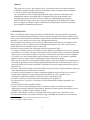
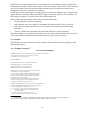
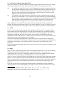
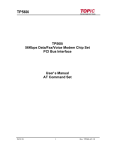
Figure 1 Diagrammatic representation of the ESP-r simulation environment
What follows is a brief description of the current environment. For more comprehensive descriptions of
the system, the reader can be referred to (Clarke 1985, Clarke and Hand et al. 1991, Hensen 1991), and
numerous topical papers and other publications.
Figure 1 shows a diagrammatic representation of the various actors, components, and interactions
involved in the ESP-r simulation environment.
The core of the system is the simulator or simulation engine (to the users this is currently known as
bps). The simulator performs the actual simulations using a product model. The latter is the complete
-4-
collection of data describing the model; ie in the current context: building, plant, fluid flow network,
occupancy, site, outdoor climate, etc.
The user side of the system is formed by the users who, via a user interface, may define and act on the
product model using various tools. The tools making up the user interface, generally fall into one of the
following three categories*:
- intelligent design assistents; high-level user interfaces utilizing state-of-the-art Information Technology
techniques, ie an ‘intelligent front end’ like the IFe);
- dedicated project tools and productivity aids; eg the general project manager prj; database managers
con for constructions, pro for event profiles, clm for climate, pdb for plant components; specialized presimulation analysers like mrt for view factors, shd for external surface shading analysis, win for spectral
analysis of multilayered window systems, ins for internal surface insolation prediction; and the
simulation results analysis module res;
- generic tools; eg as provided with the operating system (text editors, file system managers, etc),
assembled from various operating system tools (ie shell scripts), or provided by 3rd party suppliers
(either public domain like grtool, touchup, and psraster, or proprietary software like ww, ten, and
ralbrowse).
The developer side of the system is formed by the developers who, via a developer interface, introduce
new or change/ expand existing parts/ modules of the simulator. Again, the tools making up the developer
interface can also be divided into three categories*:
- intelligent development environments; high-level developer interfaces utilizing state-of-the-art
Information Technology techniques, ie an object orientated energy kernel system like the eks;
- dedicated simulation modules; which are specialized in simulating a particular aspect of the overall
problem domain like for example the existing modules bld for building form and fabric, plt for plant
systems, mfs for fluid flows, the modules under development for combined heat and moisture transport,
and for imperfectly-mixed room air modelling, and future modules for controls, site, light, etc;
- generic development tools; eg as provided with the operating system (editors, debugging tools,
program verifiers, etc), build from these (ie shell scripts), or software engineering tools provided by 3rd
party suppliers (either public domain like toolpack, floppy, and f2c, or proprietary software like forchk).
The above is merely re-iterated here, because it sketches the context in which ESP-r is ‘growing’. It also
indicates why more and more people are becoming involved with the (software) development of the
system, which itself is becoming increasingly comprehensive and complex.
Due to the growing complexity of the system and the increasing number of people involved, there is
however also an increasing risk of: duplication, negatively interacting parts of the system, undocumented
features, unsupported (partial) ‘releases’, persistent bugs, varying coding styles, etc.
The idea underlying the current report now is, that confirmation to certain accepted rules (or accepted
codes of behaviour if you like)* will decrease the risks of events indicated above, and will be beneficial
especially in the medium and long term. In the short term, however, this will involve getting used to and
also a certain degree of self-discipline of all people involved.
This report now continues with indicating the current status of the organisational structure surrounding
ESP-r. Then some points relating to good practice procedures for source code control are elaborated. This
is follewed by a chapter on good practice guidelines and examples with respect to style and documenting
of the coding itself. Finally there is a chapter indicating some Computer Aided Software Engineering
* As indicated by the dots in Figure 1 there may be tools which fall between these categories.
* It is certainly not the intention to enforce certain new elements, it is more a case of describing of what
seems to be accepted (implicit) rules/ style etc at the time of writing this report. In the future we may decide
to do otherwise.
-5-
(CASE) tools which may prove helpful for maintaining good practice.
-6-
2. ORGANISATIONAL STRUCTURE
As elaborated in the previous chapter, ESP-r is clearly a research orientated simulation environment in
which changes are taken place at a rather high pace, and from different angles. This is reflected in the
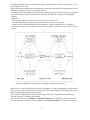
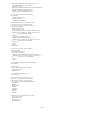
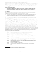
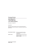
organisational structure surrounding the system, which is shown in Figure 2.
Figure 2 Diagrammatic representation of the organisational structure around the ESP-r
simulation environment
The organisational structure is like a star. In the middle there is the central archive which holds the most
recent archived version of the system. This archiving is carried out in a centralized location (the Energy
Simulation Research Unit at the University of Strathclyde), and the archive is maintained by one person
only: the archivist (ie at the moment Professor Joe Clarke).
Surrounding the archive, there are several developers which are based on decentralized locations (ie all
over Europe). Each developer may - with the permission of the archivist of course - take part or all of the
archived version of the system, in order to do the envisaged developments or changes etc. When
‘completed’, the affected parts of the system are transferred back to the archivist, who will subsequently
move them back into the archived version.
It is the archivist’s responsibility to enforce some sort of source code control in order to keep track of the
system’s development path etc. Although not done at present, in the future we may want to use some
CASE tool to aid in this task. In order to keep the system portable, this will then probably have to be a
public domain source code controller.
It is also the archivist’s responsibility to ensure that new source code developments do not adversely
affect the other parts of the system in terms of structure; ie to ensure that the system remains coherent. It
is the developer’s responsibility however, to ensure that his/ her developments are valid in terms of
contents and function.
With respect to enhancements and new developments, there might be a hierarchical "order of
responsibility". By this we mean that the final responsibility with regard to what happens to the system
(ie. which kind of developments are going to be undertaken; when and what can go in the archived
version) obviously remain with the progenitor of the system; ie. Professor Joe Clarke.
In view of the time consumption involved, it seems reasonable though that part of this responsibility/work
is delegated to other persons. Each of them might be in charge of one or more ESP-r modules. He/she
would then manage the development (in consultation with Professor Clarke), and would be the primary
-7-
contact for that specific module.
It is important to note that the archived version is basically also the current release of the complete
system. This version will incorporate all known and obvious bug-fixes, and will be updated with
extensions which were previously developed, tested and approved by both the developer(s) and the
archivist. Of course, any new additions to the system will have to be accompanied by a fair amount of
documentation regarding objective, how it works, how to use it, examples, etc.
At certain points in time, the archivist may decide to ‘officially’ announce and release a new version of
the system. As indicated above, this version will basically be the prevailing contents of the archive at that
point in time. Between two official system releases, the archived version just keeps on ‘maturing’. The
archive will thus incorporate any recent developments and enhancements. So when a developer plans to
make additions, he/ she should ‘always’ start from the then archived version.
It is also important to be aware that ESP-r does not go beyond what is generally regarded as the β -release
level. The reason for this is that all people involved are into research, and not into e.g. commercialisation
of source code. Research funding is usually not available for creating say an α -release of the system,
although we sometimes - eg in case of developing a system for teaching purposes - would like to do so.
To keep eachother informed about ongoing and planned developments, new releases, etc. some regular
schedule of general meetings might be useful. This involves travelling and costs. A - in our case - natural
alternative is to do it via e-mail; which is the background of the recent establishment of An electronic
discussion platform for ESPR (Hensen 1991).
-8-
3. GOOD PRACTICE PROCEDURES
To re-iterate what was suggested above, it is important to note that we are engineers and scientists - not
trained in computer science - for who solving a scientific problem is more important than applying
sophisticated software development methodologies. We are writing our own applications and have to rely
on the most elementary software tools - editors and compilers - to develop applications which can be
large and complex. We do so because the methodologies supported by modern software-development
tools, which are derived from commercial environments, do not fit our work habits or our budgets. By
trial and error, we have developed a methodology of our own which is based on incremental development
and focuses on code production. In a way, we usually put together an still incomplete software version
and try it out using ad hoc debugging. We like to achieve rapid solutions, and this may overshadow
concerns about requirement specifications, design phases, or documentation.
If we are not very careful, the result might be a monolithic program or module which is difficult to debug,
modify, reuse, and port - and is understood only by the developer. In short, the end product has poor
quality, which becomes apparent when code must be reused for new purposes or bugs start appearing
‘mysteriously’.
To maintain and improve the quality of the software we write and use, this report tries to give some ‘good
practice guidelines’ which are based on current group practice and seem to give a reasonable result.
The first and most important rule is that each developer is responsible for his/ her own work. This
obviously implies properly testing and documentation of your own developments. Failing to do so will
not only affect yourself but effectively all your colleague researchers as well. In the short term because
your colleagues will be suffering from your ‘bugs or flaws’, and in the long term because it is very hard to
get a good name, but very easy to get a bad name (with all related consequences).
As indicted in Figure 2 the organisational structure is like a star. Source code transfer to colleagues
should only take place via the central archive; ie. do not take code directly from colleague developers.
Also, if a new development is started, start from the archived version. This is to prevent any mix-ups.
Of course, a developer may choose to have his current work used and tested by a local group of pro-active
users, before submitting it to the archive. This will help to make the software more robust and will
prevent premature general release of the software. Obviously in those circumstances, documentation is
allowed to still be somewhat course.
Before being put into the archive any - new or altered - source code should be checked thoroughly for
errors with for example forchk (see appendix 2), lint (see your UNIX manual) or a similar package.
Obviously, such a package can only spot semantic or structural errors. Functional or algorithmic errors are
much harder to track down. You will have to find another way of achieving this; ie. the important issue of
verification and validation (see eg the PASSYS final report).
It seems to be a sensible archiving policy if somebody who submits source code (which he/she thoroughly
tested before submitting of course) to the archive, is subsequently asked to take the affected module(s)
back and check the changed version(s) in order to see if the ‘whole’ system is still ‘coherent’. This is
related to the fact that during the time you have been working on your developments, somebody else may
in the mean time have submitted something to the archive which is interacting with your developments.
This suggestion starts from realising the time constraints the archivist has to work within. It seems to us,
that with this policy everyone is only doing his/her fair share of the work involved in a team effort, and it
will lessen the work load placed upon the archiver.
Obviously this suggestion is much harder to realise - and perhaps impractical - in case of developers
abroad then when developers are located close to the archive itself.
When you submit new or altered code to the archive you also have to provide a short high-level
description of changes. This information is to be used by the archivist in order to keep a record of the
system’s development path.
-9-
When you submit new - or altered in terms of user functionality - code to the archive you also have to
supply a new - or updated - manual page - and if possible also a tutorial - for each affected module of
the system. This kind of documentation is primarily aimed at the users but is also very useful for other
developers since it gives a ‘verbose’ description of any changes in the system.
It seems like a good idea to have some reference problems (documented in the manual) associated with
each module, on which subsequents release can be tested in order to see the impact - on various problems
- of the new changes when compared with the previous release.
- 10 -
4. GOOD PRACTICE CODING
It is important that the source code has some sort of common coding style. This has an esthetic function,
but more importantly it increases the readability of the code and makes it more accessible to other (future)
developers.
Partly for the same reasons, it is also crucial that the source code is well documented.
This chapter gives a short introduction on each of these two subjects, which are then elaborated with
specific examples.
4.1. Style
In terms of code style, one of the most important things to do is to write your code in a clean and concise
fashion; ie stick to the KISS (Keep It Simple and Stupid) approach. Make sure that your code is easy to
read and understand (again) for yourself (even after some months not being involved with that particular
code) and your colleagues. This implies that in case of evaluating an equation say, it is usually better to
write it down the same as you would write down the corresponding scientific equation. Do not combine
terms - and disstort the clearness - just because this will save some CPU time. In our context, we are far
more interested in saving development time; ie kiss-able code.
Try to make your code as structured as possible. Obviously this is easier - and more natural - in C than in
But even in the latter case, there are several - sometimes only visual - possibilities to achieve
this. As a starting point you probably want to avoid usage of GOTO statements in FORTRAN.
Note that some FORTRAN compilers - like eg the Sun FORTRAN compiler - support some additional
features which give you the possibility to use high level structure mechanisms like for instance DO WHILE
loops. It is very advisable to not use such non-standard (relative to ANSI 1978) features, because they are
very likely to impose problems whenever the system is ported to other platforms or when other user/
developers use different compilers. There are however some non-standard features which are supported
by all compilers (for example usage of INCLUDE files) and may therefore be used without risk.
FORTRAN.
In principle, it should be clear which rules to apply, eg. does the code have to comply with the
ANSI/FORTRAN_77 Standard (which makes it very portable) or do we allow certain non-standard
features (eg. variable names longer than 6 characters, FORTRAN key words in lower-case, etc.). At the
moment we just treat this as a question of common adhered to style. This also implies that this is
something which will probably change continuously with time. The examples in the following subsections give a flavour of the current style.
Try to use - as much as possible - self-explaining variable/ parameter names. Don not change the meaning
of a particular variable/ parameter somewhere else in the code; for example if you use say wspeed for
windspeed don’t change change the intrinsic meaning to windspeed squared just because it is used as such
in most places. If you choose for the latter it is far better to use a variable called say wspd2 in the first
place.
Frequently, modules in scientific applications like ESP-r have a common format because they perform
similar tasks. For instance the coefficient generators for the different plant component types differ usually
only in the equations calculating the actual matrix coefficients. In case you are developing additional
modules for some feature for which there is already a ‘master format’ (eg plant component coefficient
generators, fluid flow calculators, etc) it is advisable to conform to that ‘master format’ because that is
probably more clear for a (future) 3rd developer.
4.2. Documenting
The kind of documentation this section is about, is intended to be used by developers; ie. here we are not
addressing the user manual pages. We are also not addressing the ‘high-level description of changes’ as
indicated in the previous chapter, which is used for keeping a record of the system’s development path.
- 11 -
Nobody wants to create documentation, but everybody needs it and complains when it is poorly done.
Documentation should be complete and consistent. There are two basic reasons for this. First, developers
who go back to their code after some time cannot remember details. Second, the personal context
disappears when the code is transfered to colleagues.
As with style, code documenting is very much a question of commonly adhered to style. Again this also
implies that this is something which will probably change continuously with time. The examples in the
following sub-sections give a flavour of the current documenting style.
Some general points worth noting with respect to code documenting are:
•
use proper English sentences to document;
•
each subroutine starts with a high-level explanation of its purpose and how this is achieved;
•
each subsequent (major) task or activity in a sub-routine is preceded by some documenting
comments;
•
COMMON
variables are documented in the subroutine where they are first introduced.
When these simple rules are adhered to subroutines are easy to follow and understand, and if we were to
collect all embedded comments this would almost lead to a ‘report’ of what’s going on.
4.3. Examples
The following sub-sections show some coding examples which elaborate the current coding style and
documenting strategie.
4.3.1. Example in FORTRAN*
˜esru/src/esrumfs/mfsbps.f
C MFSBPS of ESRUmfs #####################################################
C This file contains the following modules which are mfs’s general
C counterparts to be used by bps, bld and plt:
C MFLWSU MFLWCA
C In addition to this there are the more specific mfs counterparts:
C MFLW2B (in mfsbld.f) to be used by bps and bld
C MFLW2P (in mfsplt.f) to be used by bps and plt
C MFCNTL (in mfsplt.f) to be used by bps and plt
C ESRUmfs solves a network representing one-dimensional fluid mass
C flow in building and/or plant configurations.
C This involves the calculation of fluid flow through branches and nodes
C in a network which represents a building and/or plant configuration.
C The nodes and branches describe boundary pressure points, internal
C node characteristics and flow restrictions.
C ESRUmfs uses an iterative mass balance approach in which nodal
C pressures (of unknown-pressure nodes) are adjusted until the mass
C residual of each internal node satifies some criterion.
C All ESRUmfs COMMON block variables are described in ˜esru/include/flows.h.
C ESRUbps COMMON block variables associated with fluid mass flow are:
C IAIRN - building air flow simulation index (1 = on)
C ICAAS - fluid (= air) flow network node associated with each
C
building zone. NB fluid flow network and building zones
C
need not be matched
C IFLWN - plant fluid flow simulation index (1 = on)
C ICFFS - fluid flow network node associated with each plant
* Note that we are currently writing more and more FORTRAN code in lower case. ESP-r is currently in a
state of transition in that respect. This particular example is still in upper case notation.
- 12 -
C
component. NB fluid flow network and plant energy
C
network need not be matched
C LAPROB - fluid flow problem description file
C LAPRES - wind pressure coefficients distribution database
C LAFRES - fluid flow network results file
C NCOMP - total number of building zones
C NCON - total number of building intra-zone connections
C IER1 - input error index which ensures that ESRUbps menu picks
C
which are dependent on input data cannot be selected
C
if any error was detected during the input sequence
C CVI? - hourly ventilation conductance for infiltration air
C
for weekdays, Saturdays and Sundays respectively
C CVV? - hourly ventilation conductance for ventilation air
C
for weekdays, Saturdays and Sundays respectively
C ICC? - hourly convection coupling index for weekdays,
C
Saturdays and Sundays resp.: ICC?=0 ventilation air
C
at constant temperature (=TIA?) ICC?=N ventilation air
C
at zone N temperature
C TIA? - hourly temperature of incoming air during weekdays,
C
Saturdays and Sundays resp. and corresponding to ICC?=0
C
NB In case there is a leakage network, TIA? holds the
C
normalised (to the external temperature) ventilation
C
conductance
C ZMBI - zone air flow array; 1= infiltration mass flow rate;
C
2= product of zone coupling mass flow rate and moisture
C
content; 3= product of mechanical system mass flow rate
C
and moisture content; 4= total mass flow rate lost from
C
the zone (no moisture included)
C
C *** MFLWSU ***********************************************************
C This is the fluid mass flow network set up routine which:
C Opens and reads fluid flow related data files: wind pressure
C
coefficients file and flow network problem description file
C Checks fluid flow network problem description
C Assigns flow results file
C Sets iteration, Pstack model, matrix solver and trace default values
C Initialises flow, derivative and pressure history variables
SUBROUTINE MFLWSU
INCLUDE ’/usr/esru/include/building.h’
INCLUDE ’/usr/esru/include/flows.h’
INCLUDE ’/usr/esru/include/plant.h’
COMMON/OUTIN/IUOUT,IUIN
COMMON/FILEP/IFIL
COMMON/ER1/IER1
COMMON/C1/NCOMP,NCON
COMMON/C10/NPCON,IPC1(MPCON),IPN1(MPCON),IPCT(MPCON),
&
IPC2(MPCON),IPN2(MPCON),PCONDR(MPCON),PCONSD(MPCON,2)
COMMON/AFN/IAIRN,LAPROB,LAPRES,LAFRES,ICAAS(MCOM)
COMMON/FFN/IFLWN,ICFFS(MPCON)
COMMON/FFC/IMFRES
CHARACTER*72 LAPROB,LAPRES,LAFRES
PARAMETER (SMALL=1.0E-20)
IER1=0
IUNIT=IFIL+4
C Open WIND PRESSURE COEFFICIENTS file, read coefficient
C sets and close.
CALL FPOPEN(IUNIT,ISTAT,1,1,LAPRES)
IF(ISTAT.LT.0) GOTO 2
READ(IUNIT,*,IOSTAT=ISTAT,ERR=3,END=4) NPRE
DO 100 J=1,NPRE
READ(IUNIT,*,IOSTAT=ISTAT,ERR=3,END=4) (FPRE(I,J), I=1,MPOS)
100 CONTINUE
CALL ERPFREE(IUNIT,ISTAT)
- 13 -
C Open fluid flow PROBLEM file and do a simple validity check
CALL FPOPEN(IUNIT,ISTAT,1,1,LAPROB)
IF(ISTAT.LT.0) GOTO 6
READ(IUNIT,*,IOSTAT=ISTAT,ERR=7,END=8) NNOD,NCMP,NCNN
IF(NNOD.LT.2.OR.NNOD.GT.MNOD) GOTO 9
IF(NCMP.LT.1.OR.NCMP.GT.MCMP) GOTO 11
IF(NCNN.LT.2.OR.NCNN.GT.MCON) GOTO 11
C Now read contents, do further checks and then close
C the problem file.
CALL MFLOAD(IUNIT,IER)
IF(IER.NE.0) GOTO 1
CALL ERPFREE(IUNIT,ISTAT)
C Check building zone/fluid flow node (must be air node)
C connectivities. In the case of a building zone with
C no corresponding mass flow node do not check the fluid
C type (this is an array index 0).
IF(IAIRN.EQ.0) GOTO 120
DO 110 ICOMP=1,NCOMP
IF(ICAAS(ICOMP).LT.0.OR.ICAAS(ICOMP).GT.NNOD) THEN
WRITE(IUOUT,*) ’ Building zone ’,ICOMP,’ mapped to invalid’,
&
’ mass flow node ’,ICAAS(ICOMP)
GOTO 14
ELSE IF(ICAAS(ICOMP).NE.0) THEN
IF(NDFLD(ICAAS(ICOMP)).NE.1) THEN
WRITE(IUOUT,*) ’ Building zone ’,ICOMP,’ references non-air’,
&
’ mass flow node ’,ICAAS(ICOMP)
GOTO 14
END IF
END IF
110 CONTINUE
C Check plant component inter-connection/fluid flow
C connections mapping.
120 IF(IFLWN.EQ.0) GOTO 130
DO 122 IPCON=1,NPCON
IF(ICFFS(IPCON).LT.0.OR.ICFFS(IPCON).GT.NCNN) THEN
WRITE(IUOUT,*) ’ Plant connection ’,IPCON,’ mapped to invalid’,
&
’ mass flow connection ’,ICFFS(IPCON)
GOTO 14
END IF
C Check on fluid type equality will be performed by MZPMXT.
122 CONTINUE
C Assign results file.
130 CALL FPOPEN(IUNIT,ISTAT,3,3,LAFRES)
IF(ISTAT.LT.0) GOTO 13
IMFRES=IUNIT
C Fill valid fluid flow component type arrays.
CALL MFCDAT
C Sets iteration, Pstack model, matrix solver and trace
C default values. Note that iteration parameter initial
C values should be set equal to corresponding plant
C iteration parameters MAXITP, PERREL, and PERMFL.
MAXITF=100
FERREL=.01
FERMFL=.0005
PMAX=50.
STEFFR=-0.5
IPSMOD=1
MSLVTP=2
MFTRAC=-1
C Initialise flow, derivative and pressure history variables.
DO 140 ICNN=1,NCNN
HDP(ICNN)=SMALL
HDV(ICNN)=1.0
HFL(ICNN)=SMALL
- 14 -
140 CONTINUE
200 RETURN
C Error messages.
1 CALL MZEROR(0,121)
GOTO 51
2 CALL MZEROR(0,120)
GOTO 50
3 CALL MZEROR(0,121)
GOTO 50
4 CALL MZEROR(0,5)
GOTO 50
6 CALL MZEROR(0,120)
GOTO 51
7 CALL MZEROR(0,121)
GOTO 51
8 CALL MZEROR(0,5)
GOTO 51
9 CALL MZEROR(0,122)
GOTO 51
11 CALL MZEROR(0,123)
GOTO 51
13 CALL MZEROR(0,120)
GOTO 52
14 CALL MZEROR(0,124)
GOTO 99
50 CALL MZEROR(1,116)
GOTO 99
51 CALL MZEROR(1,117)
GOTO 99
52 CALL MZEROR(1,118)
GOTO 99
99 IER1=1
CALL ERPFREE(IUNIT,ISTAT)
CALL EPWAIT
GOTO 200
END
C *** MFLWCA ***********************************************************
NOT INCLUDED
4.3.2. Example in c
construction_property.h & fBconstruction_disc.c
/* +-------------------------------------------------+
*|
The EKS Project
|
*|
HEADER of class Construction
|
*|
|
*|
<<construction_property>>
|
*|
|
* | copyright @ESRU University of Strathclyde |
*|
27 March 1990
|
* +-------------------------------------------------+
*
* Header file to include functions which provide properties
* of a Construction.
*
*/
#include "layer_property.h"
int
no_of_layer();
char
**type_layer();
CMatrix *layer_disc();
/* +-------------------------------------------------+
- 15 -
*|
The EKS Project
|
*|
FUNCTION of class Construction
|
*|
|
*|
<<thermal_disc>>
|
*|
|
* | copyright @ESRU University of Strathclyde |
*|
27 March 1990
|
* +-------------------------------------------------+
*
* Function ’thermal_disc’ creates matrix equations for a
* discretised multi-layered construction based on 1, 2
* or 3-D spatial discretisation. It generates non-linear
* matrix ODE of the form:
*
*
(dT/dt) = A(T)*T(t) + B(T)*U(t)
*
* Function returns a matrix struct including matrix A,
* state vector T and vector of (B*U).
*
* Discretisation of construction is based on layers:
*
* -Construction creates a list of layers of concatenation.
*
* -Construction retrieves data of 1, 2 or 3-D discretised
* layers and allocates them in the contruction matrix equation.
*
* -Construction then modifies and creates the connection
* coefficients.
*
* -Construction allows the touching divisions of two adjacent
* layers to be combined into one common division, or each as
* stand alone division.(the current case).
*
* Function ’thermal_disc’ firstly establishes the matrix structure
* by inserting the layer matrices on the diagonal. Then calculates
* the contact coefficients for each pair of layers.
*
* C ... |C x |
|
*
|x x x|
|
*
| x X|Y
|
*
|-----+-----+
|
*
| Y|X x |
|
*
| |x x x|
|
*
| | x X|Y
|
*
| +-----+---|
*
|
Y|X x
|
*
|
... |
*
|
... |
*
|
x C| ... C
*
* in which:
* X are layer contact coefficients modified by construction.
* Y are contact coefficients created by construction.
* C are coefficients to be modified or created by class
* Contiguity.
*
* Input:
* 1. name of construction; (char)
* 2. no of layers; (int)
* 3. name of each layer; (char list)
*
* Output:
* 1. struct of construction matrix in compressed form;
*
* Note of treatments:
* 1. stateVector array stores capacities of first division of the
*
first layer and last division of the last layer.
*
{ C[1], 0, 0, ..., 0, C[n] } (where C=lo*cp*dx)
* 2. rightVector array stores resistance of first division of the
*
first layer and last division of the last layer.
*
{ R[1], 0, 0, ..., 0, R[n] }
* 3. The sequence of layers implies the concatenation, ie. the
- 16 -
*
*
*/
last division of the (i)th layer touches the 1st division of
the (i+1)th layer, and so on.
#include "construction_property.h"
#ifdef DEBUG
CMatrix *construction_disc();
main()
{
char *name;
CMatrix *out;
int i=0;
name=(char*)malloc(M);
puts("name of construction ?");
scanf("%s", name);
out=(CMatrix *)construction_disc(name);
printf("total no of nodes: %d0, out->nVar);
printf("total no of equations: %d0, out->nEqs);
printf("total no of non-zero coefficients: %d0, out->nnCoef);
puts("0osotions of non-zero coefficients :");
for(i=0; i<out->nnCoef; i++)
printf("position[%d] = %d0, i, out->pos[i]);
puts("0alues of non-zero coefficients :");
for(i=0; i<out->nnCoef; i++)
printf("Value[%d] = %e0, i, out->cCoef[i]);
puts("0tored data :");
for(i=0; i<out->nEqs; i++)
printf("Capacity[%d] = %f0, i, out->stateVector[i]);
for(i=0; i<out->nEqs; i++)
printf("Resistance[%d] = %f0, i, out->dVector[i]);
}
#endif
CMatrix *construction_disc(name)
char *name;
{
/*input and output paramaters. */
int noLayers;
char **layer_name;
CMatrix **layer_matrix, *output;
/*internal variables*/
int row, col;
register int i, j;
int count, off_set=0;
/*get data (int constant)*/
noLayers = no_of_layer(name);
/*create a list of pointers for layer names*/
layer_name = (char**)malloc(noLayers*sizeof(char*));
/*get layer names (char string array)*/
layer_name = type_layer(name, noLayers);
/*create a list of pointers for layer matrix*/
layer_matrix = (CMatrix **)malloc(noLayers*
sizeof(CMatrix *));
/*allocate output*/
output = (CMatrix *)malloc(sizeof(CMatrix));
/*get layer matrix by calling function layer_thermal_disc()*/
- 17 -
for(i=0; i<noLayers; i++) {
printf("layer<%d> : material<%s> : ", i+1, layer_name[i]);
layer_matrix[i] = (CMatrix *)layer_disc(layer_name[i]);
}
/*assign output matrix parameters*/
output->nEqs=0;
output->nVar=0;
output->nnCoef=0;
for(i=0; i<noLayers; i++) {
output->nEqs += layer_matrix[i]->nEqs;
output->nnCoef += layer_matrix[i]->nnCoef;
}
output->nVar=output->nEqs;
output->nnCoef += 2*(noLayers-1);
/*create rightVector, stateVector of output matrix*/
for(count=0, i=0; i<noLayers; i++) {
for(j=0; j<(layer_matrix[i]->nEqs); j++)
if(i==0 || i==(noLayers-1)) {
output->dVector[j+count] = layer_matrix[i]->dVector[j];
output->stateVector[j+count] =
layer_matrix[i]->stateVector[j];
}
count += layer_matrix[i]->nEqs;
}
/*create Construction matrix*/
for(count=0, i=0; i<noLayers; i++) { /*scan layers*/
int first=0, last_coef=layer_matrix[i]->nnCoef-1,
last_layer = noLayers-1, ii, j1, j2;
float capacity_p_left=0, capacity_p_right=0;
float resist_p_left=0, resist_p_right=0,
resist_e_left=0, resist_w_right=0;
/*retrieve data of adjacent nodes*/
ii = layer_matrix[i]->nEqs-1, j1 = i+1, j2 = i-1;
capacity_p_left = layer_matrix[i]->stateVector[0];
capacity_p_right = layer_matrix[i]->stateVector[ii];
resist_p_left = layer_matrix[i]->dVector[0];
resist_p_right = layer_matrix[i]->dVector[ii];
if(i<last_layer)
resist_e_left = layer_matrix[j1]->dVector[0];
if(i>first) {
int j3;
j3 = layer_matrix[j2]->nEqs-1;
resist_w_right = layer_matrix[j2]->dVector[j3];
}
for(j=first; j<=last_coef; j++) { /*scan divisions*/
/*recover relative positions in layer*/
row = layer_matrix[i]->pos[j]/layer_matrix[i]->nEqs;
col = layer_matrix[i]->pos[j]%layer_matrix[i]->nEqs;
/*create Y coefficient for the 1st division of a layer[i],
*except the very 1st layer.
*/
if(i>first && j==first) {
output->pos[count] =
(off_set+row)*output->nEqs+(col+off_set-1);
output->cCoef[count] =
2/capacity_p_left/(resist_p_left+resist_w_right);
count++;
}
/*copy layer coefficients to construction matrix*/
output->pos[j+count] = (off_set+row)*output->nEqs+col+off_set;
output->cCoef[j+count] = layer_matrix[i]->cCoef[j];
/*modify X of the 1st division of layer[i]*/
if(i>first && j==first)
- 18 -
output->cCoef[j+count] -= 2/capacity_p_left/
(resist_p_left+resist_w_right);
/*modify X of the last division of layer[i]*/
if(i<last_layer && j==last_coef) {
int a;
output->cCoef[j+count] -=2 /capacity_p_right/
(resist_p_right+resist_e_left);
/*create Y coefficient for last division of layer[i],
*except the very last layer.
*/
a = output->pos[j+count];
count++;
output->pos[j+count] = a+1;
output->cCoef[j+count] = 2/capacity_p_right/
(resist_p_right+resist_e_left);
}
}
/*end of one layer, increment, go on to the next*/
off_set += layer_matrix[i]->nEqs;
count += j;
}
/*release heaps*/
for(i=0; i<noLayers; i++) {
free(layer_matrix[i]);
free(layer_name[i]);
}
free(layer_matrix);
free(layer_name);
return(output);
}
- 19 -
5. CASE TOOLS AIDING GOOD PRACTICE
There exist a number of Computer Aided Software Engineering (CASE) tools which may prove helpful
for maintaining good practice. Some of these tools come with the UNIX operating system, like:
dbx
dbx and dbxtool are utilities for source-level debugging and execution of programs written in C,
or other supported languages such as FORTRAN. dbxtool is the SunView graphical interface for
dbx; both accept the same commands, but dbx uses a standard terminal (tty) interface. With
dbxtool, you can use the mouse to set breakpoints, examine the values of variables, control
program execution, peruse source files, and so on.
lint
a C program verifier which attempts to detect features of the C program files that are likely to
be bugs, to be non-portable, or to be wasteful. It also performs stricter type checking than does
the C compiler. lint runs the C preprocessor as its first phase, with the preprocessor symbol lint
defined to allow certain questionable code to be altered or skipped by lint. Therefore, this
symbol should be thought of as a reserved word for all code that is to be checked by lint.
Other CASE tools are so-called 3rd party products which are either public domain or proprietary
software. The following sub-sections describe a few of these packages, just to give a flavour of what can
be expected. Which tools are actually supported at your site, depends very much on available funds etc.
5.1. forchk
forchk is a FORTRAN program development aid developed at Leiden University*. Appendix 2 of this
report contains the on-line manual page for the forchk program and shows how and with wich options
forchk can be activated. It verifies the syntax, composes cross referenced subprograms and i/o for each
subprogram, and indicates how these items are used. As an option forchk validates the syntax for
conformance with the ANSI FORTRAN 77 standard, moreover it can also verify if no extensions are being
used that are not part of the comong FORTRAN 90 standard.
The reference structure of subprograms can be presented, and cross reference tables of subprograms,
commons, i/o and include files are composed. Arguments of referenced subprograms and common blocks
are checked for consistency. Cross reference tables of all elements of each common-block can be
generated.
forchk can emulate many compilers and can be used as a cross tool to convert FORTRAN programs to other
computer systems.
5.2. floppy
floppy is a public domain package which came to our attention through the NetNews on USENET (running
on the European IP network InterEUnet and the American Internet, etc); it was posted in the
"comp.sources.misc" section. It is a rather large posting of 11 parts. In the accompanying README the
author describes how to get floppy up and running on UNIX, VMS and CMS systems.
floppy is a FORTRAN Coding Convention Checker and FORTRAN code tidier. Floppy understands standard
FORTRAN 77 code. The user may specify any combination of a total of 44 different coding conventions.
These are described fully in the floppy guide, which comes as a PostScript file in the posting. Appendix 3
of the current report is the on-line manual page and shows how and with wich options floppy can be
activated.
Users may tidy their code by renumbering all statement labels, renumbering all FORMAT statements,
indenting DO and IF clauses, right-adjusting GOTOs and by moving all FORMAT statements to the end of
* Details and information about binary license fees etc. can be requested from
[email protected]. As an indication, expect to pay for a binary license fee for a Sun
SPARCstation ≈ ECU 1400 (educational institutes will receive a discount of 40%).
- 20 -
each program module. Any combination of these tidy options is possible.
floppy was initially written for VMS systems. The posting includes routines and execs that allow floppy to
be built for VM/CMS, VAX/VMS and UNIX systems. floppy was written by Julian Bunn and Hans Grote at
CERN, the European Centre for Particle Physics in Geneva, Switzerland. The posting includes a file
called "copyright".
Finally a quote from the authors:
Please also note that the source code for floppy does NOT necessarily conform to the coding
conventions it itself checks ! You may draw whatever conclusions you wish from this fact !
5.3. toolpack
The first release of the toolpack FORTRAN 77 software tools suite, was the result of an international
collaborative effort started in 1979. The original project aims were twofold:
(1)
To provide a suite of tools to assist the production, testing, maintenance and transportation of
medium-sized mathematical software projects written in standard-conforming FORTRAN 77.
(2)
To investigate the development of extensible programming support environments built around
integrated tool suites.
The Toolpack project, was supported in the U.S.A. by the National Science Foundation and the
Department of Energy, and in the U.K. by the Science and Engineering Research Council. Because of the
nature of the project funding, the resulting software is in the public domain.
NAG (Numerical Algorithms Group)** is offering a public access service. The aim of the - now obsolete
- Release 1 distribution service was to enable FORTRAN 77 programmers to make sample use of the tools
developed during and after the Toolpack project, and to provide feedback to the computing community.
NAG played a mayor role in developing and assembling Release 1, and agreed to provide such a public
distribution service. Continuing in the spirit of the public access philosophy, NAG co-ordinated the
assembly of Release 2 and has launched extended distribution and information services for this latest
release. Considerable care has been taken in preparing Release 2 for general use; indeed many of the tools
are in regular use within NAG in the development of software procucts. However, toolpack remains in the
public domain; obviously it is NOT a fully supported commercial product. To give an idea of what to
expect, here is a (partial) list of toolpack tools:
ISTAL
ISTAN
ISTCN
ISTFR
ISTLS
ISTPF
ISTPL
ISTPP
a documentation generation aid for creating formatted reports from the
information derived by other FORTRAN analysis tools.
a FORTRAN 77 instrumentor for the dynamic analysis of software.
a simple, stream based token stream editor that can be used for changing names,
strings or comments.
a tool to convert REAL, DOUBLE PRECISION, COMPLEX and DOUBLE COMPLEX
constants to a consistent form.
a long name changer, which allows FORTRAN programs to be written using long
variable names that are then mapped to legal names.
a tool that provides a FORTRAN 77 equivalent to the Bell PFORT portability verifier
(which was for FORTRAN 66).
a source code polisher or pretty printer.
a tool to ensure the consistency of PARAMETER statements between program
units.
** NAG Ltd, Wilkinson House, Jordan Hill Road, OXFORD OX2 8DR, UK
- 21 -
ISTPT
ISTSA
etc
an arithmetic precision transformer which can convert FORTRAN program units
between single and double precision.
a tool that provides a semantic analysis capability to check conformance to the
FORTRAN 77 standard.
etc
At the moment we are investigating which of the toolpack tools might be particular useful in the context
of ESP-r developments. In the near future we hope to have more detailed information concerning this.
- 22 -
6. CONCLUSION
Please regard this report as a ‘good practice guide’ for researchers involved in the development of the
ESP-r building and plant simulation environment. As such it is merely a statement of what currently
seems to be accepted (implicit) rules/ style etc by the group of developers as a whole. In the future we
may decide to alter certain things. Obviously, the follow-up of this report will then have to be changed
correspondingly.
This report presented some CASE tools which may aid in maintaining good practice. These specifice
tools are only presented here, to give a flavour of what can be expected in a general sense. Whether or not
these tools are available at your site, depends very much on available funds etc. Obviously it is only the
public domain software, which we are allowed to send around.
Finally, if you have any comments or additions to this report, please do not hesitate to express them. Also,
if you have or come across any (public domain) CASE tools which might be useful in our context, please
communicate this to us, your colleague developers.
Obviously, a good communication channel for this is the electronic discussion platform for ESP-r.
Acknowledgements
Producing this report would not have been possible without the help, discussions and support from and
with several persons. Notably at ESRU: Joe Clarke, Paul Strachan, Jon Hand and Dechao Tang; and at
FAGO: Cor Pernot, Marieke van der Laan, and Michael den Brok.
- 23 -
Appendix One
ESPR Background and History
- 24 -
The numerical engine of ESP was researched between 1974 and 1977 when the various techniques for
modelling energy flow - response functions in time and frequency domain and numerical methods - were
investigated and compared (Clarke 1977). This lead to a prototype model which used state-space
equations and a numerical processing scheme to represent all building heat flux exchanges and dynamic
interactions. Central to the model is its customised matrix equation processor which is designed to
accommodate variable time-stepping, complex distributed control and the treatment of ’stiff’ systems in
which time constants can vary by more than an order of magnitude. Within a simulation, a special
numerical technique ensures that all flow-paths evolve simultaneously to fully preserve the important
spatial and temporal relationships.
Between 1977 and 1982 ESP was extensively re-worked to allow simultaneous multi-zone processing and
to create the infrastructure to support complementary program modules covering data input, graphical
results display and interrogation, climate and construction database management; the computation of
shading, solar beam tracking, view factors and window spectral behaviour; and facilities for comfort
assessment, condensation checks, and the like.
Two other tasks were undertaken during this period: (1) model testing against hypothetical buildings (IEA
1980) and real buildings (Clarke and Forrest 1981, IEA 1984); and (2) the program was installed in a
large multi-disciplinary design practice where its application to a number of live design projects was
passively observed (Maver and Ellis 1982).
These activities lead to further theoretical and user-interface refinements so that a robust and (for its time)
user-friendly system was beginning to emerge. The predictive accuracy, while not proven, was in
diminishing doubt and, documentation was extensive and wide ranging.
Between 1982 and 1985 the system underwent its second major retrofit when air flow modelling (based
on work by Cockroft 1979), and plant simulation (based on work by McLean 1982, and Tang 1985) was
added.
The next step was to port the model to a UNIX operating system environment, running on highperformance, bit-mapped, graphics workstations. This operating system is widely regarded by computer
scientists as the best environment for writing and maintaining sophisticated software. Its main strenghts
(after MacRandal 1988) being: (1) hardware independence and standardization, (2) multitasking
capability, (3) hierarchal file system, (3) extensive range of utilities, (4) powerful command shells, (5) i/o
redirection and piping facilities, and (5) based on a software development philosophy†. Through this
move, we may now truly speak of an energy simulation environment because all UNIX tools (numerical,
documentation (for instance the typesetter used for formatting this dissertation), data retrieval, reduction,
and analysis, on-line manuals, etc) and various (public domain) 3rd party products (graphics for
exploratory results analysis, graphical editors (for instance the one used for editing the figures in this
report, etc) become available to the user at will.
By 1985 then, the ESP system was equipped to perform comprehensive energy and mass balance
simulations for combined building and plant systems when constrained to conform to distributed control
action. The system was non-building type specific and was able to handle any plant system as long as
mathematical models of the constituent components were pre-installed in the required form.
It was during this period that ESP was selected as the European reference model in the field of passive
solar architecture (CEC 1986). The system’s validity was further tested in now completed validation
projects (Bloomfield 1987, Lebrun and Liebecq 1988), and in the still ongoing EEC passive solar project
PASSYS (Gicquel and Cools 1986, CEC 1989) in which various centres throughout Europe are rigorously
testing the system against test cell experiments.
† Also according to MacRandal (1988), paradoxically, UNIX’s main weakness is its power. From the point
of the novice, the terse command syntax and the lack of feedback (essential for UNIX commands to be usable
from other programs), coupled with the expert orientated documentation, makes the whole system rather
opaque to the novice.
- 25 -
In the same period a number of organisations began to use the model commercially. And since early 1988,
a separate version of the system is being commercialised by a private company, ABACUS Simulations
Limited.
Since then we started to use the term ESP-r which refers to the research version of the system, and which
is controlled by ESRU (Energy Simulation Research Unit) at the University of Strathclyde. Several
research groups are now working with the system. For example, in North America the model is
established at Lawrence Berkeley Laboratory, at the National Institute of Standards and Technology
(formerly: National Bureau of Standards) and at the Northwest Pacific Laboratory. And in Europe, it is
operational at lead research centres in each of the EC member states.
The FAGO group of Eindhoven University of Technology has become a second major development site
for ESP-r, which is being reflected in (ongoing) research projects leading to major extensions on the plant
and fluid flow simulation side, as described by Hensen (1991), and recently initiated (Te Velde & Hensen
1991), and developments with respect to, for example, combined heat and moisture transport phenomena
(Laan 1991).
- 26 -
Appendix Two
forchk Manual Page
- 27 -
FORCHK(1)
USER COMMANDS
FORCHK(1)
NAME
forchk - Fortran program development aid
SYNOPSIS
forchk [global-options] file [[local-options] file ...]
Interactive mode: if started without parameters on the command line forchk will prompt for global options and a listfile, local options and files. An empty line or end-of-file
(control-C) indicates end of input.
Default suffixes: .f for source inputfiles (dependant on the
compiler emulation chosen), .lst for listfile, .flb for
library files. A file preceded by the -l option is a list
file. Files denoted with a .flb suffix or preceded by one
of the library options are supposed to be forcheck library
files. Any source input file must be specified before any
library file.
DESCRIPTION
Forcheck is a Fortran program development aid developed at
Leiden University. It verifies the syntax, composes cross
reference tables of constants, labels, variables, arrays,
referenced subprograms and i/o for each subprogram, and
indicates how these items are used.
As an option forcheck validates the syntax for conformance
with the ANSI Fortran 77 standard.
The reference structure of subprograms can be presented, and
cross reference tables of subprograms, commons, i/o and
include files are composed. Arguments of referenced subprograms and common blocks are checked for consistency. Cross
reference tables of all elements of each common-block can be
generated.
The global information of the subprograms can be stored in
library files. These library files can be analysed, updated
and referenced in subsequent forcheck runs.
Forcheck can emulate many compilers and can be used as a
cross tool to convert Fortran programs to other computer
systems.
OPTIONS
subprogram analysis:
-allc
Analyse all columns of the source input
records.
-cntl c
Allow a maximum of c continuation lines.
-cond
Process debug (D) lines.
-decl
-i2
Present a warning for all variables that are
not explicitly declared.
Integers occupy 2 bytes storage by default.
- 28 -
-i4
Integers occupy 4 bytes storage by default.
-relax
Relax type checking on integers, logicals and
Holeriths.
-stand
Check the syntax for conformance with the
Fortran 77 standard.
-trunc
Truncate symbolic names to 6 significant
characters.
global analysis:
-ancmpl
Signal unreferenced and undefined global
items.
-anprg
Verify the consistency of the program.
-anref
Analyse the reference structure.
output:
-l file
-plen l
-pwid w
-shcom
Make list file (’-’ for stdout).
Maximum l lines on an output page, l > 20.
Maximum w characters on a line, 60 < w < 132.
Show cross-reference tables of common-block
elements.
-shcom com Show cross-reference tables of common-block
elements of specified common-blocks.
-shinc
List statements of include files.
-shprg
Show cross-reference tables of the program.
-shref
Show the reference structure.
-shsngl
Include unreferenced constants, declared in
include files, and unreferenced common-block
elements in the subprogram cross-references.
-shsrc
List source code. Note: the -shsub option
must also be in effect.
-shsub
Show listings and cross-reference tables of
subprograms.
libraries:
-cre
Create new library file
-incl
Include library file in the analysis.
-incl mod
Include specified modules from library file
in the analysis.
-lib
The pathname specified denotes a library
file.
-upd
Update library file. If the file does not
exist, it will be created.
- 29 -
Miscellaneous:
-I dir
Set directories of include files. (’:’
denotes working directory.)
-inf
Show informative messages.
-warn
Show warnings.
Negation:
’n’ or ’no’, e.g. -nwarn or -nowarn
Options can be truncated as long as they are unique.
Option arguments must be separated by a ’,’ or ’:’.
e.g. -shcom com1,com2,com3
’--’ denotes end of options.
Defaults:
-nancmpl -anprg -anref -nallc -cntl 19 -ncond
-ncre -ndecl -i4 -nIdir -inf -nincl -nl -nlib
-plen 60 -pwid 79 -nrelax -nstand -nshcom
-shinc -shprg -shref -shsngl -shsrc -shsub
-ntrunc -nupd -warn
The options specified on the command line in front of all
files are global and effective for all inputfiles. The
options specified in front of a specific file are local and
in effect for that specific file only, they overrule the
global options.
In interactive mode, the options specified with the list
file are global and will be in effect for all input files.
An option specified with an input file is local and works
only for that input file. A local option overrules a global
option, thus different options can be used for each separate
inputfile.
The output options determine which information will be
stored in the list file. You must specify the -l option for
these options to have any effect.
EXIT-STATUS
0 no information, warning, overflow or error messages
presented
2
information, but no warning, overflow or error messages
presented
4
warning, but no overflow or error messages presented
6
table overflow, but no error messages presented
8
error messages presented
16 fatal error using Forcheck occurred
FILES
/usr/bin/forchk Forcheck task
/usr/bin/fckcnf.* Configuration files
/usr/bin/fckerr.msg File with error messages
/usr/bin/fckpwd.pwd Password file
- 30 -
Appendix Three
floppy Manual Page
- 31 -
FLOPPY(1)
USER COMMANDS
FLOPPY(1)
NAME
floppy - Fortran coding convention checker and code tidier
SYNOPSIS
floppy [ -l ] [ -c rules ] [ -f ] [ -o old file ] [ -i names
] [ -j number ] [ -F ] [ -G ] [ -r start[,step] ] [ -s
start[,step] ] [ -n new fortran ] [ file ]
DESCRIPTION
Floppy is a tool which allows a file of Fortran 77 code to
be checked against a set of common coding conventions.
Floppy also allows the source Fortran to be reformatted and
tidied in various ways.
Note that, before passing code through Floppy, it should
have been compiled, preferably with the ANSI compiler flag,
to check for errors. Otherwise, the results from using
Floppy are unpredictable. Note also that non-standard Fortran statements (such as "include" directives or lower-case)
are treated as comments by Floppy, and thus ignored.
OPTIONS
-l
The logging option causes Floppy to produce a
verbose description of the selected options.
-c rules
The checks option indicates which rules Floppy
should check. The checks may be specified as a
series of comma-separated numbers (see below),
or as one of the following:
standard The standard set of rules will be
checked (those marked * in the list
below).
a
ALL rules in the available list will
be checked.
n
NO rules will be checked. (Useful
when just tidying code.)
Note that, if selecting individual rule numbers,
99 is taken to mean ALL rules, and -99 to mean
NO rules. Specifying a negative rule number
excludes that rule. So to check all rules except
1,5,7 and 31, you can use
-c99,-1,-5,-7,-31
-f
The full qualifier specifies that all source
code lines should be listed, rather than just
those in breach of any specified rules.
-o old
Use a previously-generated file of rule numbers,
ignore names etc. The old tag should be set to
the file name, which is generated by appending
.old to the previous source Fortran file name.
-i names
Specify a list of Fortran module and variable
- 32 -
names to be ignored when the rules are checked.
Specify module names by prepending the name with
a # sign. The list of names should be separated
by commas. Note also that the names should be
uppercase, to conform with the F77 standard. For
example,
-i#GOOBAR,FOOBAR will cause subroutine GOOBAR to
be ignored, and any references to the variable
FOOBAR.
The following options apply to code tidying:
-j [number] The indent option causes all DO loops and
IF...THEN...ENDIF clauses to be indented by the
specified number of spaces to the right. The
default value is 3 spaces, the maximum allowed
is 5.
-F
Specifies that all FORMAT statements be grouped
together at the end of each module.
-G
Specifies that all GOTO n clauses are right
adjusted to column 72.
-s start,[step]
Specify that all labelled statements be renumbered, starting at start and stepping by
step. The default value for step is 10.
-r start,[step]
Specify that all FORMAT statements be renumbered, starting at start and stepping by
step. The default value for step is 10.
-n new
Causes the new Fortran file to be called new
fortran. If this option is not given, then the
new Fortran file will have the name of the
source Fortran, appended by .out
CODING CONVENTION LIST
The full list of rules is as follows:
* 1 Avoid comment lines after end of module
* 2 End all program modules with the END statement
* 3 Declared COMMON blocks must be used in the module
* 4 COMPLEX and DOUBLEPRECISION vars at end of COMMON
* 5 COMMON block definitions should not change
* 6 Variable names should be 6 or fewer characters long
7 Variables in COMMON should be 6 characters long
8 Variables not in COMMON should be <6 characters
* 9 Integer variables should begin with I to N
* 10 Variable names should not equal FORTRAN keywords
* 11 Avoid comment lines before module declaration
* 12 Module names should not equal intrinsic functions
* 13 First statement in a module should be declaration
* 14 Module should begin with at least 3 comment lines
15 Comment lines should begin with a C
- 33 -
*
*
*
*
*
*
*
16 No comment lines between continuations
17 Avoid non-standard variable types eg INTEGER*2
18 Avoid multiple COMMON definitions per line
19 Do not dimension COMMON variables outside COMMON
20 Avoid embedded blanks in variable names
21 Avoid embedded blanks in syntactic entities
22 Avoid the use of PRINT statements (use WRITE)
23 Do not give the END statement a label
* 24 Avoid WRITE(* construction
25 Avoid WRITE statement in a FUNCTION
* 26 Avoid the use of PAUSE statements
* 27 Statement labels should not begin in column 1
* 28 Always preceede STOP by a descriptive WRITE
* 29 Avoid the use of ENTRY in FUNCTIONS
* 30 Avoid using I/O in FUNCTIONs
31 Avoid the use of the alternate RETURN statement
* 32 COMMON block names should not equal variable names
* 33 Avoid use of obsolete CERN library routines
34 Avoid FUNCTION names the same as intrinsics
* 35 Local functions should be declared EXTERNAL
* 36 Module names should all be different
* 37 Avoid expressions of mixed mode eg A=B/I
* 38 Length of passed CHARACTER variables should be *
* 39 Order of statements should conform !
* 40 Separate Statement Functions by comment lines
* 41 No names in Statement Function definitions elsewhere
42 Use LLT,LGT etc to compare CHARACTER vars. in IFs
43 Variables (not COMMON, not PARAMs) <6 characters
* 44 Passed arguments should be dimensioned * in module
- 34 -
References
ANSI 1978. ‘‘American National Standard Programming Language FORTRAN,’’ ANSI X3.9-1978,
American National Standards Institute, Inc..
Bloomfield, D.P. 1987. ‘‘Work on the development of a model validation methodology,’’ Building
Research Establishment report for SERC grant, Garston (UK).
CEC 1986. European passive solar handbook. Basic principles and concepts for passive solar
architecture, Commission of the European Communities DG XVII, Brussels. P. Achard and R.
Gicquel (Eds.), Preliminary edition
CEC 1989. ‘‘The PASSYS Project Phase 1. Subgroup Model Validation and Development Final Report
1986-1989,’’ 033-89-PASSYS-MVD-FP-017, Commission of the European Communities, DG XII
of Science, Research and Development, Brussels. S. O
/ stergaard Jensen (Ed.)
Clarke, J.A. 1977. ‘‘Environmental Systems Performance,’’ PhD thesis University of Strathclyde,
Glasgow.
Clarke, J.A. and I. Forrest 1981. ‘‘Validation of ESP against test houses,’’ University of Strathclyde
ABACUS Occasional Paper, Glasgow.
Clarke, J.A. 1985. Energy simulation in building design, Adam Hilger Ltd, Bristol (UK).
Clarke, J.A., J.W. Hand, P. Strachan, J.L.M. Hensen, and C.E.E. Pernot 1991. ‘‘ESPR A building and
plant energy simulation research environment,’’ Energy Simulation Research Unit, ESRU Manual
U91/2, University of Strathclyde, Glasgow.
Cockroft, J.P. 1979. ‘‘Heat transfer and air flow in buildings,’’ PhD thesis University of Glasgow.
Gicquel, R. and C. Cools 1986. Programme PASSYS: status report, Ecole des Mines, Sophia Antipolis
(F).
Hensen, J.L.M. 1991. ‘‘An electronic discussion platform for ESPR,’’ Collaborative FAGO/ESRU report
91.37.K, pp. 1-11, Eindhoven University of Technology.
Hensen, J.L.M. 1991. ‘‘On the thermal interaction of building structure and heating and ventilating
system,’’ Doctoral dissertation Eindhoven University of Technology (FAGO).
IEA 1980. ‘‘Comparison of load determination methodologies for building analysis programmes,’’
Energy conservation in buildings & community systems programme; Annex I, International Energy
Agency. Distribution: Air Infiltration and Ventilation Centre, Coventry (UK)
IEA 1984. ‘‘Glasgow commercial building monitoring project; final report,’’ Energy conservation in
buildings & community systems programme; Annex IV, International Energy Agency. Operating
agent: Building Research Establishment, Garston (UK)
Laan, M.J. van der1991. , Eindhoven. Personal communication
Lebrun, J. and G. Liebecq 1988. ‘‘System Simulation Synthesis Report,’’ Energy conservation in
buildings & community systems programme; Final report Annex X, International Energy Agency.
Operating agent: University of Liège, J. Lebrun, report AN10 881020-RF
Mac Randal, D. 1988. ‘‘Some trends in computing: the implications for simulation,’’ Energy and
Buildings, vol. 10, no. 3, pp. 249-258.
Maver, T.W. and J. Ellis 1982. ‘‘Implementation of an energy model within a multidisciplinary practice,’’
in Proceedings CAD82.
McLean, D.J. 1982. ‘‘The simulation of solar energy systems,’’ PhD thesis University of Strathclyde,
Glasgow.
Tang, D. 1985. ‘‘Modelling of heating and air-conditioning system,’’ PhD thesis University of
Strathclyde, Glasgow.
- 35 -
Velde, K. Te, J.L.M. Hensen, and A. Roos 1991. A hybrid network and flow field method approach to
simulation of air flow in rooms, Eindhoven University of Technology. FAGO research proposal
- 36 -