1
THE
SINTEFEX AUDIO
FX8000
REPLICATOR
User Guide
Page 2
Sintefex FX8000 Analogue Sampling Digital EQ / Compressor / Effects Unit
Page 3
User Guide Version 3.0
Copyright © 2001 - 2003 Sintefex Audio Lda
SINTEFEX
FX8000
REPLICATOR
User Guide v3.0
Notice: Whilst all reasonable effort has been made to ensure that the information
in this manual is accurate, Sintefex Audio Lda accepts no liability for inadvertent
errors, omissions or changes in operating software or hardware specification referred to in this manual.
This edition April 2003
Page 4
Sintefex FX8000 Analogue Sampling Digital EQ / Compressor / Effects Unit
Contents
1
Introduction .......................................................................................................................................... 6
Welcome to the SINTEFEX FX8000 REPLICATOR.
6
Software Versions
6
Software Registration
7
About this Guide
7
2
Overview ............................................................................................................................................... 7
What is the SINTEFEX FX8000 REPLICATOR?
7
Main components of the REPLICATOR
8
What of Surround Sound?
9
Presets: Programs, Samples and Effects
10
MIDI Control
11
Installing the FX8000
11
System Block Diagram
13
The Displays and Controls
14
Input Level and Gain Reduction Display
15
3
How Do I? ........................................................................................................................................... 16
Adjust the Compressor Slope to a precise value between the steps normally provided? 16
Change the sample rate of a snapshot sample?
16
Change the view angle of the display?
16
Clear the View Angle if the screen is not viewable?
17
Connect up the MIDI?
18
Connect up the USB?
18
Edit names of programs quickly?
19
Edit samples?
19
Hold peaks on meters for longer than half a second?
22
Find a particular page or window?
23
Fix the input and output levels so they do not change?
23
Get Analogue Levels dead right into Replicator
24
Get rid of the LIMIT light or excessive distortion when replicating my effect?
25
Get the level right through an effect to be sampled?
25
Link Compressor Gain for Special Effects
27
Link Compressor Gain Between More Than One Replicator?
29
Listen to a Sample?
31
Load New Software or Presets from USB (or MIDI)?
32
Make the controls work - they do not seem to affect what I am listening to?
35
Make Replicator start up the way I want?
36
Move a Sample or Program to a different memory?
36
Register This Software?
38
Reload Replicator Software from scratch?
39
Sample an Analogue Tape Recorder?
40
Sample a Vinyl or Acetate Disk?
42
Sample compressor curves?
43
Sample Effects "Off-Line"?
47
Sample a signal processing chain?
47
Save the setup for the next session?
50
Select an Input?
50
Speed up the MIDI or USB?
51
Switch a section in and out for comparing the effect?
51
Switch the whole system in and out (bypass) for comparing the effect?
52
Switch off Replicator if the POWER button does not seem to work?
52
Sync to master sync?
52
Use Delay Compensation?
52
Use Delay Effects (in the AFX section)?
53
Use Different Samples on Different Channels?
54
Use Reverberation?
55
Use the Data Wheel, CURSOR keys and SELECT buttons?
60
Use the Expander/Gate?
61
Use Two Mono Channels on a stereo machine, or channel combinations on a multi-channel
machine?
62
View the VU or bar meters?
62
Page 5
User Guide Version 3.0
4
Copyright © 2001 - 2003 Sintefex Audio Lda
General Information ........................................................................................................................... 63
Warning and Error Messages
63
Status Display Messages
64
File Types
65
Glossary
66
Technical Specification
68
MIDI: The gory details...
70
MIDI Implementation Chart and Parameter Numbers
72
Acknowledgements, Disclaimers and Licensing
77
Licence Conditions for Version 3 Software
77
Software Registration Form
78
Page 6
Sintefex FX8000 Analogue Sampling Digital EQ / Compressor / Effects Unit
1 Introduction
Welcome to the SINTEFEX FX8000 REPLICATOR.
The Replicator takes its name from the fact that it can learn the performance of analogue systems and replicate the effect digitally. This is a new process never before available to the audio engineer and opens up new
possibilities. The Replicator FX8000 comes complete with many hundreds of sampled EQ's compressors,
signal paths and pre-set programs.
The basic operation of the FX8000 is straightforward and you probably won’t need this guide. However we
recommend that after you have experimented a little you read it through to gain a better understanding of
what is going on and how to make Replicator create the exact effect you need for mastering, mixing or tracking or indeed any audio processing application.
•
Before you start experimenting you should read the section on installation to make sure that you operate
the unit safely.
If you are looking for a unique way to change the sound of your recordings, to add warmth and colour without
leaving the convenience and repeatability of digital working, then the SINTEFEX FX8000 REPLICATOR provides and answer.
Software Versions
This User Manual is based on software version 3.0. Whilst we have made every effort to ensure that the contents are as accurate as possible, we must stress that specifications may change from those given here. Also
details of operation are expected to be revised as a result of continued product improvement.
If your software version is different this guide may still be useful. All the major functions are going to pretty
much the same and are likely to get easier to use rather than harder. If you have any real problems please
obtain the latest version of this document from our web site wherever possible at www.sintefex.com.
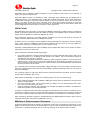
Users familiar with version 2.2 software will notice the following improvements in software version 3.0:
•
•
•
•
•
•
•
Program can be loaded seamlessly during program material with a choice of effect cross-fade (provided it
is not necessary to change the loaded model or system configuration which requires muting).
MIDI Parameter and Program changes are supported to allow automation of effect changes during a
song, compilation or performance.
New RMS compressor mode has been introduced to model optical compressor gain control, i.e. where
the program energy controls gain reduction rather than peak level.
Compressor gain half-wave mode has been introduced to allow creative use of dynamic second harmonic
distortion rather than the purely third harmonic of full wave level detection.
New Surround Sound compressor gain linkage options added, as well as new options for gain linkage in
stereo and between groups of channels.
External gain linkage is available for linking more than one machine to operate with common gain reduction, and for recording of gain dynamic profile.
Improved dynamics alias rejection during gain modulation.
In addition during the life of version 2 software the following were introduced
•
•
•
•
•
Stereo and Surround Reverberation: up to 48kHz sampling, not at higher sampling rates. A selection of
plates, room, hall, non-linear and reverse presets are available. In addition artificial reverberation may be
combined with sampled early reflections to generate previously unavailable reverberation effects. (Note
however that the FX8000 is NOT a sampling reverberator but is capable of using its sampling technology
for novel effects based on real early reflections.)
Side-chain and additional main path EQ with 4 band digital EQ allowing typically up to 8 bands of EQ if
required.
Delay management has been added so that processing delays (although very short) can be matched in
bypass or padded to a known delay.
System bypass switching has been softened so that system can be bypassed without switching clicks
Support is present for additional sample edit features when importing FX8000 v2.1 programs
Page 7
User Guide Version 3.0
•
•
•
•
Copyright © 2001 - 2003 Sintefex Audio Lda
USB communications with PCs improved under certain operating systems / conditions.
Reverse Impulse Responses: Impulse responses snapshots can be reversed in time to reverse group
delay effects. This can be used for example to compensate group delay in known recording chains, e.g.
magnetic tape or disk cutting paths.
Expander Gate: An expander/gate option is now available to add to any compressor simulation, whether
or not the original sampled machine had an expander or gate built in.
Classic EQ "POWER LINEAR" (Linear Phase) mode
Software Registration
This software is licensed for use by end-user equipment purchasers. It is free of any additional charge and is
available to all end-users subject to the licence conditions.
This software is also licensed for evaluation and demonstration by authorised dealers on a limited, renewable
licence.
We do ask end-users to register this software within approximately 3 months. Registration confirms your acceptance of the licence conditions and is free of charge to authorised end-users and removes all time limitations from the software. Registration may be done by mail, fax or via our web site www.sintefex.com. End
users need only register a software version once - no further registration of this software release is required.
See "How do I register this software" for more details.
Authorised dealers can apply for renewal licenses whenever required.
The full licence conditions are printed at the end of this user guide.
About this Guide
You don’t need a detailed explanation of every page of commands of Replicator. Most are fairly obvious and
the best way to find out is to explore the controls for yourself. This guide has two main sections - an overview
to get you familiar with the controls and layouts, and a “How do I?” section which takes you through the main
things people ask.
This guide replaces the “Operational Reference” which was getting a bit too long-winded for general use. If
you need all the details we are working on a Technical Reference manual which covers everything in detail
including general maintenance and upgrade information.
2 Overview
What is the SINTEFEX FX8000 REPLICATOR?
The SINTEFEX FX8000 REPLICATOR is a unique product which can capture an analogue signal path and
reproduce it digitally, accurately simulating the frequency response and distortion characteristics of the original. For the first time you can
•
•
•
•
•
•
•
Choose from a large library of sampled analogue EQ's, compressors and sampled signal paths to add an
analogue sound without leaving the digital domain.
Capture a favourite signal path forever for reuse at any future time
Capture a mono process and apply it identically across multiple channels, e.g. a 5.1 surround mix
Store favourite compressors for instant recall with a wider range of control that the original
Get your favourite compressor sound accurately linked in stereo or surround mixes
Work wholly digitally and get that indefinable analogue sound
You can even switch off the non-linearity if you like the analogue sound but need it digitally clean.
Replicator goes beyond the well know process of linear convolution (at least it is well known to DSP experts
even if they never let you get at it before!). Replicator’s unique and patented non-linear technology takes it
beyond this to reproduce the analogue characteristic of the sound changing when you drive the unit harder.
Page 8
Sintefex FX8000 Analogue Sampling Digital EQ / Compressor / Effects Unit
REPLICATOR Process
The word LINEAR is used in Replicator in a special way and simply applies to a sound process in which the
output follows the input exactly. If an equaliser output doubles exactly when you double the input and otherwise sounds exactly the same it is LINEAR. This is the way most digital equalisers have worked (until Replicator came along).
Most real analogue equalisers and effects do not do this and so are NON-LINEAR (NON-LIN). That’s why
your valve EQ sounds different when you drive it hard. This is one of the effects of analogue processing that
Replicator was designed to replicate.
The heart of the SINTEFEX FX8000 REPLICATOR is a new processing system known as DYNAMIC
CONVOLUTION. We won’t go into technical details here except to say that ordinary convolution has been
known for a long time but DYNAMIC CONVOLUTION is new. This takes into account not just the way things
respond to sound at one sound level like ordinary convolution, but how they respond at a whole set of levels.
This means that when you drive a REPLICATOR effect harder, it sounds different – just like an original piece
of analogue equipment.
The NON-LIN button is the quick way of switching the effect of the NON-LIN operation ON and OFF.
Linear Phase / Power Linear vs. NON-LIN
We also use the term LINEAR PHASE or POWER LINEAR in reference to sampled Classic EQ effects. This
does not refer to the LINEAR / NON-LIN effect above, but separately indicates that the phase of the effect is
linear with frequency, or to put it another way, all frequencies are delayed equally. These effects are separate
and may be combined in many ways.
How Does it Work?
Once you have a piece of analogue equipment set up to sound good Replicator takes a sample of the effect
by passing a test signal through the unit and recording the result. The test signal consists of loud signals and
quiet signal to detect the way the system varies when it is driven hard or not.
Replicator stores the results on an internal disk and this allows Replicator to recall the frequency response,
phase response and non-linearities of the equipment at any future time, and allows you to archive the effect
for as much reuse as you want.
Pre-built effects are available in a library of factory made samples of Classic EQ units and Classic Compressors. If you use these you do not need to do your own sampling.
Main components of the REPLICATOR
Familiarity
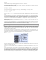
The SINTEFEX FX8000 REPLICATOR may be digital but it has a lot of familiar controls. We put a lot more
knobs and buttons than the average digital effects unit so you can get going as quickly as possible. We even
have simulated VU meters (or you can use bar meters with peak holds if you prefer).
The Equaliser
You may be simulating a Classic EQ, or you may be running a snapshot of the last EQ you used when recording say a particular vocal overdub. This uses the PROCESS section of Replicator.
In addition, REPLICATOR always provides a digital multi-band equaliser to fine tune the sound. You can get
to it with the EQ button.
The Compressor
Sampled REPLICATOR effects may or may not include sampled compressors. However even if a compressor
is not included in the effect, the SINTEFEX FX8000 REPLICATOR unit always provides a digital compressor
which is easily operated. Compressor settings are stored whenever you save settings along with the rest of
the effects for recall at a later time.
Page 9
User Guide Version 3.0
Copyright © 2001 - 2003 Sintefex Audio Lda
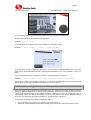
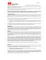
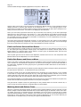
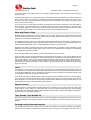
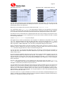
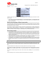
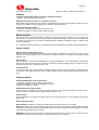
Replicator's Virtual VU meters
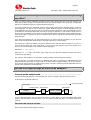
Familiar layout of the on-screen compressor
If you are using a sampled compressor the SINTEFEX FX8000 REPLICATOR can recreate both the sound of
the compressor and the way it changes with gain reduction and the ‘curve’ of the compressor, allowing soft
knee effects to be accurately recreated.
Replicator Process
The Replicator process itself can be configured in several ways:
•
Snapshot simulation of a sample of a signal path
Recreates a favourite signal path for later re-use, including the EQ settings used and simulation of any differences in the sound of the path when changing between high level signals and quiet signals. This path may
include, for example, an analogue tape path, a valve (tube) device and even loudspeaker to microphone signal paths. Compression may also be included along with the compressor section mentioned above.
•
Classic EQ simulation
Complete EQ units which have been painstakingly modelled by merging a whole lot (usually hundreds) of
samples into a dynamic, real time adjustable Classic EQ unit. We do not expect you to sample these yourself
as it can take a lot of time and may need modelling a specific set of controls..
•
Classic Compressor simulation
Complete Dynamics Compressor units which have been modelled by sampling signal paths and dynamic
characteristics into a dynamic, real time adjustable Classic Compressor unit. You can sample your own compressors but those that we have built into Classic Compressors are easy to call up and use.
AFX: Delays Echoes and Reverberations
AFX which stands loosely for After Effects can add a little icing on the cake of Replicated effects. A useful
range of effects are available to extend the use of Replicator. For use up to 48kHz sampling rates there are a
number of interesting reverberation programs for use in stereo or in multi-channel surround. Reverberations
are not sampled but they can be mixed with ambient reflection samples that create some new effects.
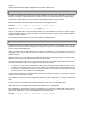
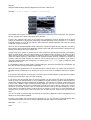
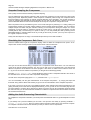
What of Surround Sound?
The SINTEFEX FX8000 REPLICATOR is available as a 2 channel, 4 channel, 6 channel or 8-channel unit.
A six-channel unit can support processing of 5.1 or 6.1 surround sound by applying your favourite EQ or compressor across all 6 channels (for 6.1 processing connect the 6 main channels and do not process the LFE
channel). Compressor gain can be linked so that there is absolutely no image shift as the compressor operates - all channels may be locked together. In addition channels can be connected to multiple gain link buses,
which may also be loosely linked together. For example the front 3 and the rear two channels can be firmly
linked, and a loose linking applied between them so a big gain reduction in the front three also pulls down the
rear gain by a proportionally smaller amount. See "How do I Link Compressor Gain for Special Effects?" for
more details.
Page 10
Sintefex FX8000 Analogue Sampling Digital EQ / Compressor / Effects Unit
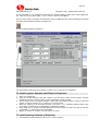
Surround Sound compressor example screen shot.
A four channel Replicator may be used for surround mixes where it is not required to process a centre or sub
woofer channel. This is favoured by many music mixers.
An eight channel Replicator may be used for 7.1 surround processing, or for 5.1 surround together with a
spare stereo channel (or indeed two mono channels), or for two quad surround groups, or 4 stereo groups or
8 mono groups.
Regardless of the number of channels fitted, you can always configure Replicator in combinations of 7.1, 5.1,
quad, stereo and mono up to the maximum number of channels available.
Presets: Programs, Samples and Effects
Programs, Samples and Effects in Replicator are held on an internal hard disk.
As with many music synthesisers and to allow familiar MIDI support for program selection, Each of these
memory types has 8 banks each of 128 memories. (That’s over 3,000 memories in total!).
PRESETS
These are simply any program, sample or effect that has been supplied with the unit or is provided from our
library on our web site.
There is a growing library of SAMPLES and PROGRAMS allocated to the top four banks of memory. In total
you have memory for 1024 SAMPLES and 1024 PROGRAMS and the presets supplied either with the machine or from our growing library of effects available on the internet, provide some good starting points for
your own creativity.
To save you having to move everything around as more presets become available we recommend that you
keep banks 5, 6, 7 and 8 free for presets so you can download them into their designated locations.
PROGRAMS
Whenever REPLICATOR is making a sound you like, you can save it as a PROGRAM. A Program remembers every setting necessary to recall that same process. Since there are 8 banks of 128 programs you
should have more than enough. In addition REPLICATOR has a hidden bank of the last 128 programs you
were working on when either you loaded a program or switched off the unit. You can load these using the
“undo” feature of the disk save and load display and this may just save you from losing forever that sound you
had just a minute ago, before you wiped it. Programs remember which SAMPLE or EFFECT you were using
to make the sound.
NOTE: When you upload a program for archiving or download a program you also need the various samples
that may be used to get that program sound.
SAMPLES
When you take a sample of an audio chain REPLICATOR stores the information as one or more SAMPLES.
These can be combined into PROGRAMS to get just the sound you want. (Synthesiser users may compare
this with all the settings on a synth (PROGRAMS) versus the raw SAMPLES of a sound).
EFFECTS
Effects comprise Classic EQ and Classic Compressor models which have been assembled by careful use of
multiple samples and have been combined into complete EFFECTS. This is usually a time-consuming task
Page 11
User Guide Version 3.0
Copyright © 2001 - 2003 Sintefex Audio Lda
and frequently needs to have some special user interfaces developed for each EFFECT. For this reason
EFFECTS appear only as factory presets. (Synthesiser users may consider this loosely like building up complex multi-sampled sounds for a music synthesiser).
What is the advantage of 24-96 technology?
The SINTEFEX FX8000 REPLICATOR supports audio word width of 24-bits on its digital input and output and
it uses 24-bit analogue converters. Working with higher word sizes means that you preserve dynamic range
throughout a process and only need to “bit-reduce” at the end of an entire production process to the final distribution media.
The SINTEFEX FX8000 REPLICATOR can do over 1,000,000,000 floating point calculations per second (per
2 channels) to fully support 24-96 operation. 32-bit floating point processing is used throughout for virtually
unlimited dynamic range with 24-bit precision. However when running at 96kHz Replicator has less time for
processing each sample which (a) halves the number of steps in the convolution chain, and (b) halves again
the duration of any convolution lengths. This affects the choice of optimum sampling rates as mentioned below.
Should I work at 96kHz, 48kHz or 44.1kHz?
If you are working on digital material your best choice would be to use the sample rate of the material you are
working on and go digitally into and out of Replicator - unless the effect you want dictates running at a lower
sample rate in Replicator.
Otherwise we liken the choice to that of using 30ips or 15ips analogue tape.
•
96kHz is like 30ips, giving you a cleaner top end and allowing you to run smoothly through 20kHz up to
the thirties and into the forties. This is at the expense of a poorer bottom end due to Replicators simulation “window” acting like a “tape head” of fixed width.
•
48kHz or 44.1 kHz is like 15ips; the top end is constrained to around 22 - 24kHz but the bottom end is
cleaner and flatter. Of course, there is no equivalent to “tape noise” so that is not an issue.
At lower sampling rates Replicator can reproduce more ambience or stored energy in the original sample.
This is a better choice for gross distortion effects or mechanical systems involving for example loudspeaker
and microphone simulations.
MIDI Control
General
This software version features MIDI control of parameters and program loading. The system will also transmit
program load and parameter control messages if desired.
Full details and a MIDI implementation chart are at the end of this guide.
Saving MIDI setup
The settings for enabling MIDI are saved with the power-up settings of the FX8000. These settings are saved
when the system is powered down or if a "save setup" is performed in the "power-up state" page.
Installing the FX8000
Mounting the unit and connecting AC power
The FX8000 is a standard 2U rack mount unit. It is fan cooled and accordingly does not require cooling space
above or below the unit, giving the maximum packing density in a rack installation. Ventilation holes must not
be obstructed and a free flow of air should be available at the sides of the unit and from the fan at the rear.
Before connecting AC power check that the voltage rating matches your AC supply. Depending on the power
supply fitted and local regulations you may be able to set the voltage to the correct setting for your area, or
the unit may be supplied pre-set for the area you are in.
Page 12
Sintefex FX8000 Analogue Sampling Digital EQ / Compressor / Effects Unit
For optimum performance the power supply should be uninterrupted. Once connected the power switch on
the rear panel (if fitted) should be left "on" and the front panel power button used subsequently for normal
operation. This allows orderly shutdown of the FX2000 processes and saving of operating set-up on the
FX2000's internal hard disk.
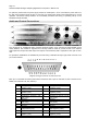
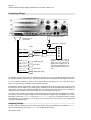
Audio and Control Connections
The connectors for unbalanced audio, balanced analysis signals, clock, optical and coaxial SPDIF are all
clearly labelled. The FX8000 is supplied with multi-way break-out leads to provide access to the balance
audio inputs and outputs and AES inputs and outputs. One break-out lead is required for each pair of channels.
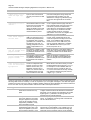
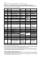
For permanent installations the FX8000 may be wired using a standard 25-way D-type male connector. The
pin-out is as follows:
1
2
3
4
5
6
7
8
9
10
11
12
13
14
15
16
17
18
19
20
21
22
23
24
25
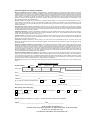
Diagram of D-type connector as seen from rear.
Each pin is connected as follows (multi-channel machines have a pair of channels on each connector as labelled, thus channels 1&2, 3&4, 5&6 etc):
Pin #
1
2
3
4
5
6
7
8
9
10
11
12
13
Connection
Analogue out channel 1
positive (“hot”)
Ground
Analogue out channel 2
positive (“hot”)
Ground
Analogue in channel 1 positive (“hot”)
Ground
Analogue in channel 2 positive (“hot”)
Ground
Ground
Digital AES out channels
1&2 positive (“hot”)
Ground
Digital AES in channels 1&2
positive (“hot”)
Ground
Pin #
14
15
16
17
18
19
20
21
22
23
24
25
Connection
Analogue out channel 1
negative (“cold”)
Ground
Analogue out channel 2
negative (“cold”)
Ground
Analogue in channel 1 negative (“cold”)
Ground
Analogue in channel 2 negative (“cold”)
Ground
Ground
Digital AES out channels
1&2 negative (“cold”)
Ground
Digital AES in channels 1&2
negative (“cold”)
Page 13
User Guide Version 3.0
Copyright © 2001 - 2003 Sintefex Audio Lda
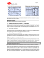
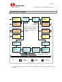
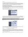
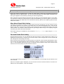
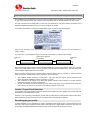
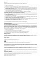
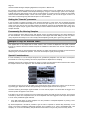
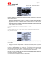
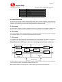
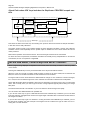
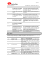
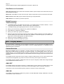
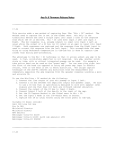
System Block Diagram
SPDIF/ADAT
digital in
instrument
analogue in
24-bit 96kHz
A-D converter
router
to channels
3-8
mixer /
router
SPDIF/ADAT
digital out
Stereo 24-bit
D-A converter
from channels
3-8
channels 1 and 2 shown
only – this section can be
repeated to a total of 8
channels
24-bit 96kHz
D-A converter
AES digital
in
AES digital out
Input Gain
Control
Output Gain
control
4-band
parametric
EQ
Compressor
Dynamics
REPLICATOR
processor (EQ,
signal path etc)
After Effects
(delays and
reverbs)
compressor gain linkage
busses (2 private, 2 public)
KEY:
•
Digital
Processing
Digital
Interface
Analogue
Conversions
It is possible to change the order of the 4 main processing elements but the diagram shows a typical arrangement.
Page 14
Sintefex FX8000 Analogue Sampling Digital EQ / Compressor / Effects Unit
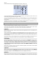
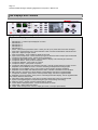
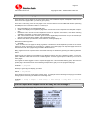
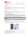
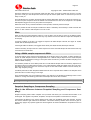
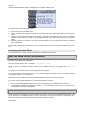
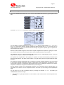
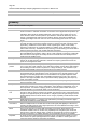
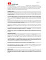
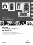
The Displays and Controls
Replicator Displays and Controls
1. Select Button 1 - selects option displayed on screen
2. Select Button 2
3. Select Button 3
4. Select Button 4
5. Select Button 5
6. Power - safe power up and down button - saves your set-up on power down and mutes analogue
7. Input Select -accesses the input / output selection screen, precision level displays and sample rate
8. Input Gain - digital input gain control
9. Input Level Display - gives confidence display of all inputs
10. Input Track and Clip LEDs - shows whether input gain is active and warns if input clips are detected
11. Compressor Threshold Control - instant access to threshold
12. Compressor Gain Reduction Display - gives confidence display of all channels gain reduction
13. Compressor Attack - quick pre-set of 3 options
14. Compressor Release - quick preset of 3 options
15. Compressor Slope - quick preset of 3 options
16. Compressor Gain Reduction Link (between channels) - links all grouped channels or pairs of mono
17. Replicator Process NON-LIN on/off - ON when simulating level dependent analogue path
18. Replicator Process DRIVE control - level control into level sensitive analogue simulation
19. Replicator Process LIMIT and LINEAR indicator LEDs - indicates if simulation is level sensitive
20. EQ in/out/call - quick press to call the display of the digital EQ, hold down to bypass/enable
21. Compressor in/out/call - quick press to call compressor diaply, hold down to bypass/enable
22. Replicator Process in/out/call - quick press to call analogue simulator display, hold for bypass/enable
221b. Where Sherlock Holmes lived
23. After Effects (AFX) in/out/call - quick press to call after effects page, hold for bypass/enable
24. System in/out (digital bypass of all processing and gain except mixing and routing)
25. Data Entry Knob - changes currently selected data on display
26. Cursor Buttons left/right/up/down - moves around values on screen
27. Output Gain - digital output gain adjust
28. Output Track and Clip LEDs.- warns if output gain active or if output clips detected
Page 15
User Guide Version 3.0
Copyright © 2001 - 2003 Sintefex Audio Lda
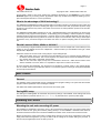
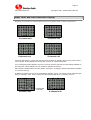
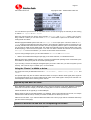
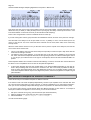
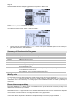
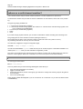
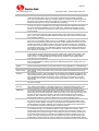
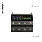
Input Level and Gain Reduction Display
Depending on the number of channels fitted, the Input Level Display takes on different appearances:
2-channel unit
4-channel unit
6-channel unit
8-channel unit
2-channel units feature a central peak hold bar and an indicator of operating level on either side of each 3
column display. All other displays use the top LED of the bar as a peak hold indicator.
If you need higher precision displays, there are a choice of precision peak and VU meter displays available on
the LCD screen. These LED bars serve as confidence indicators at all times.
Gain reduction indication follows the same pattern, and there is a peak gain reduction hold indicator available
on 2-channel units only.
In addition the bottom LED acts as an expander/gate indicator. Here is a 2 channel unit with expander/ gate
active on channels 1 and 2, and a 6 channel unit with expander/gate active on channels 1,2 and 5:
expander/gate
indicators
2-channel unit
6-channel unit
Page 16
Sintefex FX8000 Analogue Sampling Digital EQ / Compressor / Effects Unit
3 How Do I?
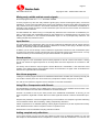
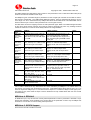
Adjust the Compressor Slope to a precise value between the
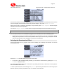
steps normally provided?
Select "display setup" from the compressor page.
COMP -> display setup
Move the CURSOR DOWN to the Slope Control field at the bottom of the screen. Select the "Slope control" to "Variable".
Press "back" to return to the compressor controls page.
Compressor slope can now be adjusted in steps of 0.1 between 1:1 and 30:1.
•
•
•
This page also allows selection between peak and RMS detector modes and FULL and HALF-WAVE
rectification.
The middle section of this page allows various modifications to the compressor display.
This page also allows zooming into the knee area of curve graph (it can display plus or minus either 16dB
or 4dB around the knee).
Change the sample rate of a snapshot sample?
Whenever you load a sample that does not match the current sampling rate in force at the time of loading you
get the opportunity to sample rate convert the original sample.
Sample rate conversion on loading is quick and the sample may be saved again at the new sample rate if
desired (usually to a different memory location).
Sometimes samples can sound okay without conversion in which case there will be a shift in pitch of the frequency response characteristics of the sampled signal path. This may not be noticeable for sample rate
changes between say 44.1kHz and 48kHz but you can try it both ways to see which effect is best.
See “How do I Move a Sample or Program to a different memory?” for detailed information.
Change the view angle of the display?
Like all LCD displays you need to adjust the view angle according to the way that Replicator is mounted, or to
accommodate temperature variations.
Whenever the system is powered up the DATA knob is initially connected to the LCD view angle adjustment
so an immediate adjustment can be made. (If the unit is switched on from cold you may not want to do this
until the machine has warmed up as the display may be slightly dark when cold).
Page 17
User Guide Version 3.0
Copyright © 2001 - 2003 Sintefex Audio Lda
The "view adjust" field shows the adjustment number that you may become familiar with.
For adjustments later you can select the start page again
SYSTEM -> start screen
or you can go tot he "screen and LED" page to adjust the view angle as follows:
SYSTEM -> setup & sample -> config -> screen and LEDs
The DATA wheel is ready to adjust the view angle or you can select 4 brightness adjustments for the panel
LEDs and the Input/Gain Reduction LEDs. (LED brightness adjustment may not be available on some systems).
You can save these settings so they apply every time you start the system by selecting
SYSTEM -> setup & sample -> more setup -> power-up options -> save setup.
This saves the LCD and LED settings as well as the current choice of audio input, clock source and the other
options shown on this page, which are then applied every time you switch on.
Clear the View Angle if the screen is not viewable?
If the view angle has been adjusted beyond a usable range, it is possible to temporarily disable the software
setting by restarting Replicator in its “debug” mode of operation. This is done by switching off all power and
waiting 10 seconds. Then power up with SELECT BUTTON 1 held down. You get a lot of messages which we
use to debug systems but within a few seconds you will be in the familiar user interface. Follow the instructions “How do I change the view angle of the display?” and save the new view angle.
This operation (of starting up in “debug” mode) is also useful to
•
•
Find out what is going on if there is a hardware problem on start-up, or
Prevent the system initialising the disk effect storage system if there is a problem with the file system.
Page 18
Sintefex FX8000 Analogue Sampling Digital EQ / Compressor / Effects Unit
Connect up the MIDI?
The MIDI IN and MIDI OUT connections are clearly labelled on the rear panel of Replicator. These are intended for connection to a MIDI sequencer for real time control of some parameters and for program loading.
The Sequencer MIDI output should be connected to the Replicator MIDI IN, (and vice-versa).
Make sure Replicator is enabled for MIDI communications. On Replicator select
SYSTEM -> setup & sample -> more setup -> remote control.
Select the “MIDI Remote Control? yes” and press “do it”.
Then go to the MIDI Setup screen and select whether you want Replicator to transmit or receive program
change messages, and if you require parameter control select whether to send or receive SYSEX or NRPN
parameter control messages.
For more details see the section at the end of this guide on the MIDI support.
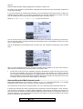
Connect up the USB?
Universal Serial Bus is the latest desktop bus allowing efficient connection of peripherals to PCs. It is designed to be much faster than the old serial ports common on old PCs, and more versatile than the parallel
port for connecting external devices.
USB is connected using a single lead that carries data in both directions. It is connected from the PC end
(“upstream”) which uses a wide flat connector, towards the external device (“downstream”) which uses a
squarer connector.
Most PCs have a one or two USB ports and USB external devices have a single socket or a captured cable.
Replicator has a socket for the squarer downstream end of the cable.
The signal can be split using a “hub” so one connection from the host can split multiple ways to many downstream external devices. Hubs can be plugged into hubs with only two limits:
1.
2.
A maximum of 5 hubs can be placed between the host and the external device. (But be careful - a host
PC often has a hub built in which counts as one. meaning only 4 external hubs in series are allowed), and
A maximum of 126 devices can connect to a single host root port. Of course a host can have more than
one root port but for now 126 devices is probably plenty.
A cable must be a maximum of 5 metres and by using five 5m cables and 4 hubs you can place the external
device up to 25 metres from the host PC.
So the physical connection can be a single USB cable from the PC to Replicator, or a string of cables and
hubs.
The PC must be running Windows 98 or better. Windows 95 or NT does not have USB support.
USB cables may be hot-plugged without switching off either the PC or the Replicator.
When Replicator is first attached to the PC and Replicator is set make use of USB ("USB remote control?:
yes" in Replicator's remote control page). the operating system will notice the connection. Its response depends on the "USB setup:" chosen on the Replicator remote control screen.
SYSTEM -> setup & sample -> more setup -> remote control.
Page 19
User Guide Version 3.0
Copyright © 2001 - 2003 Sintefex Audio Lda
The preferred USB setup is "standard" and Windows will request that a disk is inserted with the appropriate
hardware driver. Windows can then be told to look in the drivers folder of the Replimat software which you
have downloaded from www.sintefex.com. (Other options may be available here, but their use is not covered
in this manual.)
Subsequent connections will not require any user intervention unless you change the "USB setup" to a different setting.. Each time you plug in or start up Replicator the operating system notices and the connection will
be made. You usually see the cursor change to an hour-glass for about half a second.
The exact steps to take are as follows.
Select the “USB setup: standard” and
select the “USB Remote Control? yes”
and press “do it”.
Respond to any requests from Windows for drivers if this is the first connection. You will find a text document
giving instructions in the Replimat directory if you need further information.
Run the REPLIMAT software on the PC and in the main menu bar select System | USB and if Replicator is
successfully attached you will then be able to select “Show Input” and then “Test echo” or “Inquire” to get
useful information from Replicator. You can then exit from these dialogs and Replimat is ready for file transfer
or remote control.
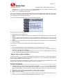
Edit names of programs quickly?
You can use the cursor controls to step forwards and backwards through the name of the program or sample
before saving it. The data wheel changes the letter displayed. Two things that make this quicker are:
1.
2.
Turning the data wheel quickly accelerates its action so it can quickly move near the end where the
capital letters and some punctuation are located.
If you move the cursor to a character BUT DON’T LET GO OF THE CURSOR BUTTON WHEN YOU
GET THERE - turn the data wheel clockwise and the rest of the name scrolls off to the right. This way
you can (a) insert some space, or (b) clear the rest of the field quickly by pushing it off the end.
Edit samples?
Samples are usually stored unedited on disk. When you load a sample it is processed according to the edit
parameters, which are stored with it on disk and have a preset value if it is a new sample.
Assuming you have a sample loaded (use the SYSTEM -> preset -> samples page to load a sample)....
Select PROCESS -> edit sample
to get to the sample edit page.
Page 20
Sintefex FX8000 Analogue Sampling Digital EQ / Compressor / Effects Unit
You can vary any of these parameters but the change is not immediate. You must press “re-load sample” to hear the effect. This is non-destructive editing - the sample on disk is not altered.
At this stage the sample on disk also does not have its pre-set edit parameters changed. You do not need to
do that if you save the current set-up as a PROGRAM, because the program will remember the alterations
you have made.
If you want the sample always to come up with the different edit settings you have selected - for example at
the very least you may have fine-tuned the “Add gain” so the sample comes up at unity gain - you can select “save edit to disk” and replace the sample with the new edit values or store it as a new sample.
The sample data on disk is not altered unless you select one of the options listed below - these settings will
alter the data permanently but of course if you save it in a different location the original is unaffected.
Data is altered if
1.
2.
3.
You have switched "Dejitter" to "yes"
If you switch "Auto sample rate convert on load" to "yes" and the current clock rate does not
match that at which the sample was originally taken.
Pitch shift is not zero.
In any of these cases the data is heavily processed using a high quality sample rate conversion algorithm and
at the same time the other parameters are permanently applied.
Add Gain
This is the amount of gain adjustment to apply to the whole sample when it is loaded and should be set so
that when the sample is bypassed the level on A/B is about the same.
Pitch Shift
This re-tunes the sample for special effects, for example to change the resonance of an effect. This is similar
to sample rate conversion but is specified in semi-tones so for example a resonant effect can be tuned to a
particular musical effect. You will find this most effective when there is a distinct pitch present in the effect, for
example a resonant peak at a given frequency.
Note that this does not alter the pitch of the signal that you are passing through Replicator. This alters the
frequency response of the effect you have sampled.
Smooth Levels
Replicator takes multiple samples of original analogue equipment at a sequence of differing levels. It is normally necessary to apply a moving average over a range of these levels to ensure that spurious noise or other
effects do not generate unacceptable deviations from the original response. The default of averaging (or
smoothing) over 16 level samples is suitable for many effects but this number can be increased to
•
•
reduce non-linearity
eliminate noise problems
Trim start - end
Replicator normally takes impulse samples of 2048 samples duration.
Initial delay in the original sample can be trimmed off by increasing the "trim start" until the impulse response
is right at the front of the displayed impulse curve. Some devices have significant delay before the peak of the
Page 21
User Guide Version 3.0
Copyright © 2001 - 2003 Sintefex Audio Lda
impulse and care should be taken not to trim off too much and affect the sound, but this may be a trade off
between processing delay and sound quality.
If there is excessive noise or unwanted impulse data after the main response of a device, the end of the sample may be trimmed off as well. Normally this is not required.
When replicating an effect at 96kHz, the simulation length is only 1024 samples. You will find that if you trim
the start to an offset greater than zero it is possible to advance the end point to a full 1024 samples beyond
the start point and this is often desirable to get the maximum "window" on the impulse sampled.
Level low - high
Replicator takes 128 samples at levels from about 40dB below peak level up to peak level (for more information see the section on sampling). This section allows you to choose a subset of these samples in the simulation.
Low level impulse response may be lost in noise, and the default value here is to discard the bottom 20 impulse responses for this reason, starting at response number 21.
•
•
Lower this figure if the original device was very low noise and you wish to preserve low level non-linearity.
Raise this figure if the original device was very noisy or you want only higher level signals to run into nonlinearity.
If the higher level impulse responses taken by Replicator were very distorted you may want to remove them
from the simulation. Setting a number less than 128 discards these top level responses.
Add Delay
After you trim the start of the impulse, you may want to add back some delay, for example to match a real
delay elsewhere in a system. This allows you to do that. However remember that the total convolution length
is limited so adding a lot of delay here will reduce the active length of the dynamic convolution simulation, as
you are adding "silent" impulse samples into the start of response.
Dejitter
You may have taken a sample from a device that had variable time delay, for example an analogue tape machine where the wow and flutter results in a jittering of the sample position within Replicator's sampling window. When you load the sample the varying position of the impulse data will cause the replication process to
function incorrectly.
Switch "Dejitter" to "on" and reload the sample to apply a complex de-jittering algorithm to the data. In this
process, the samples are examined for to determine their peak response to an accuracy of 1/256th of a sample. The samples are then sub-sample positioned in time to an accuracy of better than 100 nanoseconds so
that these points line up exactly in all the samples in the complete set of 128 samples. In addiiton, the samples will be phase corrected so that this peak impulse is positive in phase and located at precisely 20 samples
delay in the Replicator sample window. This gives consistent delay in simulation while allowing an initial impulse response to build to the maximum as if often encountered in analogue samples.
If you have any jittering in a sample you must switch this system on to get a correct sounding sample.
Reverse
This causes the impulse response to be loaded "backwards" or time reversed. This will have a very similar
sound as the frequency response will be the same, but it will usually show:
1.
2.
Increased delay, as the peak impulse is usually moved from the beginning to the end, and
Time reversal of group delay characteristics.
Group Delay is the technical term for the way that most audio processors have different delays at different
frequencies. This is true of all practical analogue equalisers and most other analogue signal paths like disk
cutters, tape recorders etc. This spread of delay across the audio band results in smearing of transients and is
often blamed for loss of stereo imaging, particularly in older recordings.
Page 22
Sintefex FX8000 Analogue Sampling Digital EQ / Compressor / Effects Unit
If it is possible to sample the original recording equipment and to reverse the response, a lot of the group delay problems can be cancelled out. In fact the frequency response is the same as the original so some extra
EQ correction may be needed, but the group delay is equalised out which is otherwise almost impossible to
achieve, and the overall effect can be used to restore stereo imaging precision in older recordings.
Auto sample rate convert on load
When you load a sample that was taken at a different clock rate all frequency dependent elements of the effect will be shifted with the sample rate unless you sample rate convert. For example a sample of an equaliser
with a 1kHz notch taken at 48kHz will load as a 918.75Hz notch at 44.1kHz (if you do not sample rate convert), or as a 2kHz notch at 96kHz.
Whenever you select to load a sample taken at a different clock rate from your current one you will be asked
whether you want to sample rate convert as follows:
Here you can choose the options shown. If you do not choose to sample rate convert you can use the edit
page later to switch it on and reload the sample. This will then retune the effect to the correct frequencies for
the clock rate you are using, so for example the 1kHz notch above will once again be accurate. Conversely if
you did choose to convert you can use the edit page later to switch the conversion off again.
Hold peaks on meters for longer than half a second?
INPUT -> levels.
Use the CURSOR DOWN key to move to the peak hold time field . You can choose between 500mS (half a
second), 1 second, 4 seconds, and one month (i.e. essentially permanent hold).
Press peak clear to clear any peaks which are being held for a long period.
Press input / output to see the meters on the input page.
In this page you can also set up default levels for VU meters and bar peak meters. If you are working close to
peak digital ()dBFS) a value of -4dB for zero on the VU may be appropriate. If your analogue VU meters are
set for zero VU at +4dBu and the digital peak is +18dBu then a level of -14dBFS is the closest match to the
analogue VU meters. However, because the digital VU meters are actually peak sensitive they will probably
read higher than true analogue meters.
Finally you can digitally trim the analogue input levels separately for all the analogue inputs for precision setup.
Page 23
User Guide Version 3.0
Copyright © 2001 - 2003 Sintefex Audio Lda
Find a particular page or window?
There are quite a lot of pages for the LCD screen which control different aspects of Replicator. Quite a lot of
these link to other pages which you need to get to quickly.
There are 5 main entry points to LCD pages. Four of these relate to the CALL/BYPASS buttons (excluding
SYSTEM) and one to the INPUT button. A summary is:
•
•
•
•
•
EQ: This displays the in-built digital EQ page.
COMP: This displays the compressor page which controls the in-built compressor and sampled compressors.
PROCESS: This controls the main Replicator Process of “Dynamic Convolution”, and allows selecting
and editing of samples or control of the Classic EQs.
AFX: This controls the After FX which gives access to digital delays and echoes of up to 32-seconds per
channel (16 seconds above 50kHz), and reverberation options
INPUT: This allows input selection, clock selection, metering displays etc.
Note that the following button...
•
SYSTEM:
...does not select an LCD page but simply bypasses or enables the whole Replicator process for the current
channel or group of channels you are working on. However, the system page is an important page and can be
reached from most other pages using the bottom SELECT button.
Many pages have a list of options down the left side that may be selected by pressing the matching SELECT
button.
Pages that do not appear to have labels for the SELECT buttons may have “Vanishing Labels”. To find out,
press a SELECT button and see if a list of labels appears. If it does it gives options or allows you to move to
other pages.
In this guide we often suggest a route to a particular page from a recommended starting point, often from the
system page. We show these as in the following example which gets you to the program load page:
SYSTEM -> programs
Similarly to get a large VU display you follow
INPUT -> big meters
Some functions are a few more button pushes away, for example use the following for tidying up the effects
storage system and sorting the effects into ascending order…
SYSTEM -> setup & sample -> more setup -> disk manage -> tidy disk -> sort effects.
Fix the input and output levels so they do not change?
Select the Input / Output page using the INPUT SELECT button.
Page 24
Sintefex FX8000 Analogue Sampling Digital EQ / Compressor / Effects Unit
You will see a page like the one shown here. The input gain and the output gain may be selected to operate
from the front panel control by selecting
Inp Gain: “control”
Out Gain: “control”
If you do not want any gain adjustment on the output, and say 0.7dB gain on the input, select
Inp Gain: “program” 0.7dB
Out Gain: “none”.
When you select “program” you can move the cursor to the gain setting and choose a gain using the DATA
knob.
This setting affects the current channel or group of channels you are operating. If you have a stereo Replicator you are either operating on both channels together as a stereo group or as two mono channels, in which
case you can set the gain separately for each, or have one channel controlled from the front panel control and
one preset. You will need to switch to the SYSTEM page to change between channels you are controlling.
When you have a channel or group selected that is set not to use from the front panel level control, the
TRACK light will go out.
If you have a multi-channel Replicator, the process is the same but there are more combinations of channel
groups available. See the section “How do I Use two mono channels on a stereo machine, or channel combinations on a multi-channel machine?” for more details of channels and grouping.
Get Analogue Levels dead right into Replicator
Replicator is supplied with preset analogue gains into and out of its analogue converters. Unless otherwise
ordered +18dBu on the balanced inputs and outputs equals peak digital audio. Other values can be supplied
in 2dB steps from +10dBu to +24dBu.
All preset values can be up to a 1dB inaccurate due to variations in the converters and analogue circuitry. To
allow accurate matching from your analogue environment to the digital environment the gains can be trimmed
digitally after conversion and the following page shows the current settings for these trims:
INPUT -> levels.
Move the CURSOR down to the channel that you want to trim and adjust the gain after the A/D converter up
to plus or minus 6dB in 0.1dB steps.
Here you can also set up default levels for VU and bar meters and set the peak hold times to a variety of values.
If your external equipment is set up so that 0VU gives +4dBu, this is 14dB below +18dBu, so you may choose
the setting shown above which sets the VU simulations to show 0VU at -14dBFS. This is a good setting if you
like digital headroom and your desk VU’s will match Replicator’s (at least on steady tones - Replicator’s VU’s
are a bit more peak sensitive than real VU’s). If however you are working near to peak digital you will probably
find the VU simulations hitting the end stops all the time, so you may want to set zero on VU to (say) -4dBFS.
Page 25
User Guide Version 3.0
Copyright © 2001 - 2003 Sintefex Audio Lda
Get rid of the LIMIT light or excessive distortion when replicating
my effect?
When you make a sample, Replicator samples the signal path including the gain of the path. Because you
often have to adjust the gain for a specific effect when you make a sample it can end up with a sample that
reduces (or increases) the gain of a signal that passes through it.
If you find yourself turning up the DRIVE (which is simply a gain control into the sampled effect) to “make up”
the missing gain you may not get the effect you wanted. Because samples are level dependent (they can
sound different as you turn up the gain like an analogue processor often does) turning up the DRIVE is turning
up the feed into the sampled effect and can result in running into distortion. In fact when the signal gets to a
level through the simulation which equals the loudest impulse passed through the original equipment, Replicator has to LIMIT the signal as it has no information about how the original device would have responded
above this level.
If you switch the NON-LIN off you cannot get limiting as you remove the level sensitivity, but you also lose
some of the level dependent characteristics of the original process you are simulating.
The solution is to reduce the DRIVE to avoid the distortion and to add gain after the sample. If you are in a
hurry just lift the output gain of the whole device, or if you want to finely adjust the gain of the sample for future use you can edit the gain of the sample in the following page:
PROCESS -> edit sample
Select the Add gain field in the edit box and increase it by a few dB. Then reload the sample and it will include the new gain setting.
See "How do I Edit samples?" for information on editing samples and resaving them if desired.
You can tell when you have the amount of additional gain right by bypassing the PROCESS using the
PROCESS button (remember you have to wait for the LED to flash to toggle the effect). As you turn the sample on and off there should be no significant gain change. This will of course be program dependent when the
sample has a significantly non-flat response.
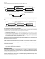
Get the level right through an effect to be sampled?
Connect up the analysis path
Connect up the signal path that is to be sampled (see "How do I Sample a signal processing chain?").
In summary the signal path is like this...
monitoring (mute)
main output
analysis output optional pad
FX8000
optional pad
device to sample
Turn any monitoring down until you have levels set up. It is then useful to monitor the FX8000 main output
quietly to hear the effect of the test pulses - you can become familiar with signs of excessive distortion for
instance.
Generate the setup level tone
Select the sampling level setup page as follows:
Page 26
Sintefex FX8000 Analogue Sampling Digital EQ / Compressor / Effects Unit
SYSTEM -> setup & sample -> sample -> level setup.
The example screen shows the typical results of sampling a "transparent" piece of equipment. The waveform
will vary according to the effect of the system being sampled.
If there is any automatic gain control in the system being sampled this must be switched off for the signal
analysis, as it depends on varying level pulses being accurately assessed. Set a compressor to 1:1 or raise its
threshold and keep an eye on its gain reduction. Gain reduction is sampled separately (see "How do I sample
compressor curves?" for details).
When an effect is sampled Replicator sends a sequence of pulse-like signals through the device. The first of
these pulses is at the peak level and Replicator expects to get a peak level response back. If the signal is any
less the stored sample will have a reduced gain.
However there are a number of reasons that you need to adjust the gain through the device to be sampled.
When the peak signal is being sent the processor to be sampled needs to be driven to its peak. This often
means that any input level control needs to be adjusted. If there is no input level adjustment it is possible to
reduce the analysis signal out of Replicator but this should be avoided wherever possible as it reduces the
accuracy of the lower level samples. (It is better to use an external pad if one is available). If you need to
change the analysis output level of Replicator you need to press "level setup" again to restart the pulse
stream at the new level.
It is acceptable to allow the peak signal to overload slightly the device being sampled as the Replicator will
then allow the effect of slight overload to be simulated.
When you have the greatest level you can push through the external device, you need to get this back into
Replicator so that (a) Replicator is not clipping, and (b) you are as close as possible to peak input to Replicator.
If the device to be tested has an output gain control this can be set with Replicator’s input gain set to 0dB so
that the input clip red LED is just on the point of lighting.
If you want to drive the external device as hard as possible you may find that the return input to Replicator
shows input clip (red LED illuminated). If one is available we suggest introducing a 6dB or 12dB pad after the
device being sampled but before feeding back into Replicator. This will allow, for example, a tube output stage
to drive to say +24dBu or higher without overloading Replicator - and this is a sound that can be useful to
sample as often these devices have a characteristic sound when the output stage is working hard. You may
also like to be sure that you have a 600 ohm termination present if there is an output transformer. A transformer without a termination resistor produces severe low frequency errors which of course Replicator will
reproduce if this is what it sees. If this is the sound you are after of course, sample it the way that sounds
best!
You can now make up the exact gain by increasing the input gain of Replicator until the level display on the
display is as close to 0dB as possible.
The gain of the sample may well be frequency dependent so you may still have to make adjustments later
when loading the sample. This can be done by editing the "add gain" option of the sample in the
PROCESS -> edit sample
page.
Page 27
User Guide Version 3.0
Copyright © 2001 - 2003 Sintefex Audio Lda
Link Compressor Gain for Special Effects
Stereo Gain linking is straightforward in normal use. Simply select a stereo pair of channels and press the
LINK button to link or unlink the gains. As you can see on the meters, the channel gains are linked so the
same gain is applied on both channels, preventing the stereo image shifting.
Mono channels can also be linked in stereo pairs this way, letting you use two different settings or even different compressor models for the left and right of a signal, but still allowing you to link the gains. To do this both
channels must have their LINK button set to ON (with the LED lit). (But see note "Matching Attack and Release Times" below).
More About Simple Gain Linking
Compressor gain reduction is linked so that the channel that would generate the most gain reduction has its
gain reduction applied to both channels. This means that a very loud sound appearing, say, on the left, will
push the gain down on both channels resulting a drop of level on the right. This keeps the centre of the image
exactly located. It is possible to reduce the effect of gain linkage without turning it off completely using the
new public gain busses. More about this below...
New modes of linking are available from the Compressor "display & setup" page, using the "linkage
setup" button.
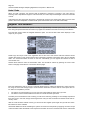
Surround Sound Gain Linking
Surround Sound groups of 4, 6 or 8 channels have their gain linked in a more powerful way to allow you to
separately link say the front 3 channels of a surround mix (left, centre and right) and the rear channels (left
rear and right rear, and possibly rear centre).
Each surround sound group has an A and a B link bus. To start with, all the channels are assigned to the A
bus so will be firmly linked together if LINK is switched on. However, to link the front 3 channels (say on channels 1, 2 and 3) together and the rear 2 (say on channels 5 and 6) together, simply connect the first three
channels to the A bus and the rear pair to the B bus, like this:
You can see that channel 4 is set to "isolated" from the gain link so will not apply its gain reduction to the
other channels.
When the compressor page is displayed, you can see which bus each channel is linked to: the meter is labelled A or B, and is labelled '-'. Here is an example:
Page 28
Sintefex FX8000 Analogue Sampling Digital EQ / Compressor / Effects Unit
Another option may be that you do not want the Low Frequency Effects channel, or even perhaps the centre
dialogue channels, to have any gain reduction at all. Simply set it to "off". In this setting its gain is not affected at all but it shares the sound of passing through the same signal path as all the other channels for consistency across a surround mix. If it is off an 'X' is displayed in the meter area.
Now if you want some proportional control from say the front bus to the rear bus, you can add a percentage
effect from the A bus to the B bus. If you set this to 50% then a gain reduction of say 4dB on the front bus will
generate a gain reduction of 2dB on the rear pair (of course this will only be applied when the rear channels
are not already achieving at least 2dB of compression for themselves). You can independently set a proportion from the rear to the front as well.
The screen above shows this example with channels 1, 2 and 3 linked on the A bus, channel 4 (LFE) isolated
(but still being independently compressed), channels 5 and 6 (rear) linked on the B bus, and a 75% linkage
from the front channels to the rear pair, but only a 25% linkage from the rear to the front.
Public and Private Surround Gain Busses
The A and B busses are normally private to a surround group. However you can select the busses to be public. This allows gain linking between multiple groups. For example two 4 channel surround groups can be
linked together, or a surround group can be linked to a stereo group as described below. (But see note
"Matching Attack and Release Times" below).
Also the public gain bus can be linked to other Replicator machines. See "How do I Link Compressor Gain
Between More Than One Replicator?" for more information.
Public Gain Busses and Stereo or Mono
There is one public A and B gain linkage bus that is available to surround groups as well as stereo groups or
mono channels. All channels linked to the public A bus will have the same gain, as will all channels linked to
the public B bus, regardless of which group they are in (provided that LINK is switched on for that channel or
group of course).
Stereo and mono groups that are not selected to public linkage are linked normally as stereo pairs whenever
the LINK button is switched on - as described at the top of this section.
The public A and B bus can also be linked together with a percentage mix of gain reduction, so it is possible
to use these on a single stereo channel pair for, say, a 50% gain linkage between channels, or they can be
used to softly link a rear stereo pair to a front stereo pair or surround group on a different group of channels
with a different effect. (But see note "Matching Attack and Release Times" below).
The proportional linkage on the public busses may be set from any group that is selected to the public bus,
but this value will affect all the groups selected to use the public bus together.
This gives almost complete control over gain linkage for many creative effects in surround or stereo use, or
even for using some audio channels to modulate others for special effects.
Matching Attack and Release Times
When the compressor gain linkage busses are used for linking between different groups of channels, the gain
linked is subject to the final attack and release times of each different group of channels or each mono channel. Within each group of channels these are guaranteed to be all the same so channel gain is exactly
matched. Between different groups or different mono channels you will need to set the same attack and release times on each channel to ensure exact stereo matching. Alternatively you can set them differently for
special effects, for example where you are using one signal to modulate another.
Page 29
User Guide Version 3.0
Copyright © 2001 - 2003 Sintefex Audio Lda
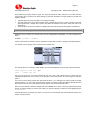
Link Compressor Gain Between More Than One Replicator?
The FX8000 is now very flexible in the way that gain is linked between channels. In particular there is a "public" pair of gain linkage busses. See "How do I Link Compressor Gain for Special Effects?" for more on this.
This pair of busses can be made public to more than one Replicator by use of the SPDIF connection on the
Replicator FX8000 (provided of course you are not using this for audio!).
If you select "external link" on the Gain Linkage Setup page, you will see the following page:
Here you can see that you can select the FX8000 external gain linkage to be off, or for the machine to a
master or slave.
If you have two or more Replicator machines you may connect them in a loop for gain linkage.
spdif coax in (gain link
on FX2000)
spdif coax
in
FX8000 master
FX8000 slave
spdif coax
out
FX8000 slave
The master SPDIF output connects to the first slave SPDIF input. This machine SPDIF output then connects
back to the master SPDIF input, or it may be linked to a third Replicator SPDIF input. The final slave must
have its SPDIF output linked back to the master.
Select one of the machines to be a master and the rest to be slaves. Now any channel you select to use the
public A and B bus will link with any other channels on all the machines.
•
•
•
The COAXIAL SPDIF connector must be used - this code does not support optical connection (this
leaves the optical available for ADAT connection of course).
The compressor is still subject to the attack and release controls in each machine. For proper matching
make sure these are set to the same settings.
At least one channel of must be selected to use a public group bus on every machine for the group linkage to work. If no channel is connected to the public bus the link will not work.
Caution: Proper Clock Selection
It is important that all the Replicator systems that are linked together are also digitally synchronised. This will
be the case in most digital environments.
However if you are working "all analogue" you will need to make sure the machines are locked to each other.
Select the SPDIF as the clock source in the clock select menu of all the slave machines.
Recording the gain profile
A single Replicator can be selected as a master, provided that the SPDIF output is connected back into its
own input. This has the benefit that if the signal is split and fed to a digital audio recorder, the gain data can
be recorded. If multiple Replicators are linked the signal can be split off at any point in the loop.
Page 30
Sintefex FX8000 Analogue Sampling Digital EQ / Compressor / Effects Unit
gain profile to digital recorder
spdif coax in (gain link
on FX2000)
spdif coax
in
FX8000 master
spdif coax
out
FX8000 slave
FX8000 slave
Recording with multiple Replicators (above)
gain profile to digital recorder
Recording with a single Replicator (below)
spdif coax
in
FX8000 master
spdif coax
out
It is then possible to "play back" the gain profile into a machine (or a set of machines). If all the machines are
now set to "slave" mode the recorded gain data will cause the recorded gain reduction to be applied to the
bus.
spdif coax
in
spdif coax
out
FX8000 slave
spdif coax in (gain link
on FX2000)
FX8000 slave
optional slaves
FX8000 slave
gain profile from digital recorder
An Application for Recording Gain Data
A typical situation where this method of recording gain reduction profiles in invaluable is where it is necessary
to provide sub-mixes, say for film soundtrack work. The requirement is as follows:
•
•
A full soundtrack is mixed in 5.1 surround, and the music producer sets the correct amount of dynamic
gain reduction for the entire mix.
It is then necessary to supply multiple parts of the mix for film dubbing each with only some of the instruments included, for example, rhythm track, orchestra, vocals (with fx), lead instruments (with fx). These
are intended to be replayed together with equal level to recreate the original mix, but allows the film director to rebalance parts if necessary during the final film dub.
Normally it is not possible to do this so that if all the parts are mixed together in the dubbing suite with equal
levels the same overall result is achieved as the original mix, because the dynamics compressor performs
differently when instruments are removed.
Using the gain profile recording method described, a first pass is made with all the instruments and the gain
profile is recorded to a spare pair of tracks of the digital recorder (in some cases only one track is required).
Then, for each sub mix, the gain profile is replayed so the exact gain profile of the full mix is applied to each
sub mix. This ensures that the sub mixes will all add together to re-create the original mix as desired by the
music producer and engineer.
•
•
Note that when replaying data this completely overrides any internally generated gain.
When replaying the gain profile, the compressor is still subject to the attack and release controls. For
proper matching make sure these are set correctly.
Gain Data Format
The gain data format is proprietary to Sintefex Audio but may be recorded on any digital recorder proved that
it does not alter the signal in any way. The format uses 24-bits of data, but the method described above will
work fine with a 16-bit recorder. However, the signal path between Replicators must be a full 24-bit path - do
not break into it except as described above.
The data is flagged as normal audio so that it will not cause problems to the digital recorder. The A-bus is
carried in the left channel and the B-bus in the right. If you are only using one of these busses you will only
need one track, otherwise you will need two.
Page 31
User Guide Version 3.0
Copyright © 2001 - 2003 Sintefex Audio Lda
Avoid monitoring the gain reduction signal. The signal (if treated as audio) will have a lot of DC and bass
content and if fed to monitors may cause damage. In particular transients in the gain profile may create loud
impulsive signals.
•
•
•
The gain signal cannot be recorded on an analogue recorder.
The gain signal cannot be recorded if fed through a sample rate converter or other processor. Note that
some DAW's have a sample rate converter chip fitted as standard on all inputs. These will need to be
switched off.
The gain signal cannot be recorded on a digital system that uses perceptual coding (MP3, minidisk etc).
Listen to a Sample?
Replicator has one section per channel which runs the full Replication PROCESS. To load a sample into it
select
SYSTEM -> presets -> samples
If the process section is already in use you will have to confirm that you want to change to sample simulation.
You will then see the sample choice screen that can look like this:
The internal disk can contain up to 1024 samples so to limit the displayed choice the two areas at the bottom
"Show samples in bank all"
"with
sample rate all"
and
can be set to show only one of the 8 banks and only one of the 4 main sample rates. To do this user the
CURSOR DOWN button to move down to the field then use the DATA knob to scroll through the selection
options.
If you want to load a library sample they are usually in banks 7 or 8. Samples you make yourself are usually
stored in banks 1 to 4. The screen above shows a number of samples made at two different sample rates and
also show that the name you give samples can be helpful if you choose a sensible name.
After you have selected a bank and sample rate use CURSOR UP to return to the main page area and scroll
through to find the sample you want to hear. When you have the sample you want the hear highlighted press
"load sample".
If the sample rate for the sample you chose is correct for the current sample rate, the sample will load and you
will see a screen like this:
Page 32
Sintefex FX8000 Analogue Sampling Digital EQ / Compressor / Effects Unit
In addition the sample processor will be switched on and (provided the system is not bypassed) you can pass
a signal through the machine and hear the effect of the sample.
Two things you can vary on this screen are "drive" and "attack mod" which may be varied by moving the
CURSOR to the relevant field and turning the DATA knob.
"drive" is the gain before the sample. If the sample is reducing the signal significantly, you should make up the
gain after the sample using the output gain control. The DRIVE will increase the gain before the sample but
will likely lead to distortion as you can only drive the sample to peak digital level. Turning up the drive will
usually result in limiting taking place. You can later fine tune the gainof the sample using the "edit sample"
option.
"attack mod" is an advanced option which allows some modification of the way the simulation takes place. It is
allows the level selection process that monitors the incoming signal to assess the level dynamically to progressively change to an envelope detection system. This can be used mainly with gross distortions to get
some interesting effects.
•
NOTE: If the sample loaded was from a source that may contain jitter, you must go to the edit page and
switch the de-jitter option on, then reload the sample.
To edit the sample see and “How do I edit samples?”.
For an explanation of “multi-sample” see “How do I Use different samples on different channels?”
Load New Software or Presets from USB (or MIDI)?
Sintefex Audio makes new software and presets available on its web site. These are downloadable from the
internet using your normal browser or using an FTP file transfer program and are ready for transfer to Replicator.
Files may be of the following forms:
1.
2.
3.
4.
5.
.RFX files: These are new Replicator Effects
.RSM files: These are Replicator Samples
.RPG files: These are Replicator Programs and contain the complete setup of Replicator for a particular
effect.
.ZIP files. These are described below
.LDR files*: These are new software releases that may be transferred to Replicator using REPLIMAT
For a summary of all file types commonly used see the general information section at the end of this guide.
Files can be transferred to Replicator using a PC running Sintefex Audio REPLIMAT software, which is available free of charge to all Replicator users.
*Loader (LDR) files and Replimat software are usually stored in a zipped file (.ZIP) for transfer over the internet. These are zipped using commercial zipping software for two reasons:
1.
2.
The files are the smallest that can store the necessary information, and
The files are checked by the unzipping function to ensure they have not become corrupted in transmission.
Use commercially available unzipping programs to get the contents of the zipped files. Usually you unzip the
Replimat software into a folder called "replimat" and the Replicator software into a folder called *replicator".
These names are up to you but we recommend you keep them separate.
Page 33
User Guide Version 3.0
Copyright © 2001 - 2003 Sintefex Audio Lda
To use REPLIMAT on a PC equipped with Windows XP, Windows 98(SE) or better and a USB (or MIDI) port
see “How do I Connect up the USB?”, or see “How do I Connect up the MIDI?”.
Once you have made a connection with Replicator, select the REPLIMAT File Transfer Manager by pressing
the toolbar with this starburst legend. It looks like this…
The File Transfer Manager looks like this:
It is now possible to select the sort of transfer you want to do, for example PC to Replicator.
To send Programs, Samples and Effects to Replicator:
1.
2.
3.
4.
5.
6.
Select “PC to Replicator”,
Using the top right “Browse” button find a folder on your PC which contains all the programs, samples
and effects you want to transfer. Select any file in that folder to select the folder.
Tick the require boxes for Program, Sample or Effect Send and enter the bank or range of banks and
number or range of numbers (e.g. 1,2,4-8) that you want to transfer.
Make sure anything you do not want to transfer is not ticked - e.g. in “Operating Software Send” make
sure nothing is ticked unless you are updating the Replicator software.
Finally press “GO”. If you get a message saying that connection cannot be made, see “How do I Connect
up the USB?”, or “How do I Connect up the MIDI?”.
Wait for the transfer to complete, or go and have a cup of tea.
To send Operating Software to Replicator
•
You should have at least Replimat version 2.1 for correct operation.
Page 34
Sintefex FX8000 Analogue Sampling Digital EQ / Compressor / Effects Unit
1.
2.
3.
4.
5.
Select “PC to Replicator”,
Make sure the boxes for sending Programs, Samples and Effects are unticked.
Tick "Main" to update the main Operating Software on Replicator. Click on the browse button and browse
to a folder which contains the .LDR file containing the desired software to send. (This can be the same
folder as used for other things).
It is recommended that you send only one of the three operating software at a time and that you do not
send any programs samples or effects at the same time.
After loading the software, restart Replicator so that the new software can take effect.
Uploading Samples and Programs for archiving
1.
2.
3.
4.
5.
6.
Select “Replicator to PC”,
Using the top right “Browse” button find a folder on your PC into which to uploads all the programs, samples and effects you want to transfer..
Tick the require boxes for Program, Sample or Effect Send and enter the bank or range of banks and
number or range of numbers (e.g. 1,2,4-8) that you want to transfer.
Make sure anything you do not want to transfer is not ticked
Finally press “GO”. If you get a message saying that connection cannot be made, see “How do I Connect
up the USB?”, or “How do I Connect up the MIDI?”.
Wait for the transfer to complete, or go and have a really strong cup of tea.
You can’t upload Effects or Operating Software in case you were wondering.
Advance Options
To send Graphics to Replicator
Graphics Resources just means things that aren’t built into the software but used by it. At the moment this is
just the graphic images that Replicator uses. From version 2.0 software these are built into the .LDR file supplied as the new software release. However if there are any problems with the graphic images on Replicator
after the software is updated you can send a fresh version of the Graphics from Replimat as follows (you
should have the latest Replimat for correct results - check our web site.).
1.
2.
3.
4.
Select “PC to Replicator”,
Tick "Enable Advanced" to allow for this special option,
Make sure the boxes for sending Programs, Samples and Effects are unticked.
Tick the “Resources” Graphics box to send the latest graphics to Replicator.
Making Waves
This is an obsolescent function that allows a WAV file to be created containing coded Replicator software or
downloads. It is not recommended that this method of Replicator update is used now.
Other items
In case you are wondering what this button is for…
This button is the RECALL button for any “report box” that Replimat sometimes shows.
Report Boxes are boxes in which Replimat puts occasional useful information. It does not stop you carrying
on (you can ignore it without having to press “Okay”). After a report box has been on the screen for few seconds it goes away of its own accord.
The recall button brings back the last report box if you missed it or want to read it again. If there have been a
number of report boxes recently every time you press RECALL you go back to an older one.
At the moment these are used only by the WAV file reader but in future this will be used for other useful reports.
Renaming PC files
Programs and samples are recognised by REPLIMAT by the first section of their name, e.g:
program bank 7 #3 (tight delays ).rpg
sample bank 8 #15(ls to mic 1m ).rsm
Page 35
User Guide Version 3.0
Copyright © 2001 - 2003 Sintefex Audio Lda
If you requested to load a program bank 2 number 7, REPLIMAT will transfer the first occurrence of a file
matching the name
program bank 2 #7*.rpg
where the * matches any name.
You can therefore change the bank and number of a program or a sample by changing the file name. The
information in brackets is optional and is put in by REPLIMAT from the name stored with the sample or program to help you identify it.
Effects are different and although we use the convention, for example
fxb1p014.rfx
to indicate the effect for bank 1 number 14, the name can be anything provided it has the .rfx suffix. The bank
and program number are embedded in the file and cannot be changed.
REPLIMAT will download the first file with extension .rfx it encounters which has the correct bank and number embedded in it, regardless of name.
Several versions of uploaded files
When REPLIMAT uploads programs or samples from a Replicator to a PC it looks to see if the specified bank
and number has already been uploaded. If it has, the upload continues but REPLIMAT adds a (1), (2), (3) etc
to the end of the file name to indicate that it is a newer version of the uploaded program or sample. You may
want to delete or rename older versions so that that do not get downloaded again in error.
Make the controls work - they do not seem to affect what I am listening to?
You are probably listening to a channel that is not the one selected on the front panel. The controls only affect
the currently selected channel or group of channels (if they are grouped together). If you don’t know about
grouping channels, see “How do I Use Two Mono Channels on a stereo machine, or channel combinations on
a multi-channel machine?”.
The input and output level controls usually affect all channels, unless they are set to a fixed input and output
gain. (See “How do I fix the input and output levels so they do not change on an effect I have fine adjusted?”).
Select the System page which looks like this:
The data knob selects amongst the groups or channels available which will be highlighted in black. The picture shows channels 3 &4 selected as a stereo pair.
The system graphic shows that of the 4 main processing block, only the Classic EQ is used for this program.
The name of the last loaded file is shown at the top.
Select the channel or group you need to adjust. You can then return to the page you are working on and the
controls should be working for this group.
Page 36
Sintefex FX8000 Analogue Sampling Digital EQ / Compressor / Effects Unit
Make Replicator start up the way I want?
SYSTEM -> setup & sample -> more setup -> power-up options
provides a page which allows you to make certain decisions about power-up.
The selection shown "Load power down state" is the most common. Replicator always saves its last operating state when you press the POWER off button at the end of a session. The next time you power up after
setting this option the close down operating state is restored.
If the power is interrupted other than by the power down button, the state is not saved but Replicator does
occasionally store an "undo" state whenever certain operations are performed. The last such state will be
loaded at the following power-up.
Other options are "Don't load anything" which prevents Replicator from loading any previous state at
power up. You may want this if
•
•
•
you like a clean start at every power-up, preferring to load a saved program by hand
you habitually get many power outages so shut down saves are rarely performed, or
you power off the whole setup centrally without using the power down button.
Finally you have the option "Load the default program". This always loads the program shown below it
at power up and is useful if you like to always start with a known state, or if for example Replicator is in a
permanent live installation with the same starting setup every day. You can of course choose the bank and
memory number for the program to load.
What is Saved and Restored on Power-up
The following is saved at power down and restored at power up before any other operation is performed
1.
2.
3.
4.
5.
6.
7.
8.
9.
The choice about what to load on power up described above
The clock rate of the system
The clock source (whether internal, reference, digital input, or automatic)
The audio source for each channel (analogue, digital, balanced, unbalanced etc)
LCD view angle setting
Meter level settings for 0dBVU
Peak meter hold time
Fine gain adjustments of digital inputs.
USB and MIDI remote control options.
Move a Sample or Program to a different memory?
To move a sample:
1.
2.
3.
4.
5.
Go to the sample load page (SYSTEM -> presets -> samples) and choose and load the sample
you want to move
Go to the “save” page (PROCESS -> edit sample -> save edit to disk)
You may want to rename the sample in the name field at the bottom of the screen
Select the bank and sample number where you want to save the sample.
If you have different samples in different channels you can select whether you want to save a single
sample, for example “Save samples from:ch 1” or saving a group of samples from a multiple sam-
Page 37
User Guide Version 3.0
6.
Copyright © 2001 - 2003 Sintefex Audio Lda
ple set-up “Save samples from:all” . If you choose more than one a sequence of memories will be
highlighted for you to verify that the destination locations are free.
Press “save” to perform the save to disk.
If one of the memories you will be writing to is not empty you will be asked to confirm the save. You can also
select never to be asked this question again which is useful if you are deliberately overwriting a large selection of samples. (This is reset at next power on).
If you have not edited the sample name you will see the following screen...
The options give you the following choices:
1.
2.
3.
4.
Do the save with the unedited name
Do the save with the unedited name and do not present this screen again (until reset by the next power
down)
Append a 3 digit number automatically in the last 3 characters of the sample name. This is incremented
on every future save and you will not be prompted with the query again (until reset by the next power
down)
Abandon the save - this returns to the save screen and allows you to manually edit the name or abandon
doing it altogether.
The automatic numbering is useful when you are saving a large number of items .
Thing to note...
•
•
•
The original sample remains at the original location so you actually have a new copy of it
Any programs that use this sample will continue to use the old copy unless you edit those programs or
create new ones using the new sample.
You only get the chance to save multiple samples in one go if you have a multiple sample program set
up. See “How do I Use different samples on different channels?“.
“Sample has not been reloaded…”
If, when you select “save” you get a message like the one above it is because you have made changes to
the edit values displayed but you have not reloaded the sample, so you are not listening to the sample the
way the currently displayed edit values indicate.
If you want to save what you are listening to, confirm the save. If you want to save the edited version, reload
the sample first, make sure you are happy with the sound of it, then select “save”.
To move a program:
1.
2.
3.
4.
5.
Load the program you want to copy to a new location. (SYSTEM -> programs). If you want to save the
information for all channels to a new location load the program by going into the "more options" and select "load whole system". This will load all the channels on the system not just the one(s) you are working
on.
Select "save" to get a display of saved programs and empty memory locations.
Scroll the an empty memory location in the list, or one you want to overwrite.
Edit the name if you want to.
Press “save program” and a copy of the program is made at the new location. (You will have to confirm that you want to overwrite an existing program if the memory is in use).
Page 38
Sintefex FX8000 Analogue Sampling Digital EQ / Compressor / Effects Unit
Undo / Redo
When you load a program, the previous state of Replicator is saved as a program in the undo memory.
Pressing “undo” steps back through the undo memories, and “redo” steps forward again. There are 128 levels
of undo.
Undo saves are also done when the power is switched off using the front panel power button (but not when
power is removed or Replicator is turned off with power switch at the rear on the PSU when fitted).
Register This Software?
After installation this software will operate normally for approximately 3 months (720 hours) of use. At any
time during this period authorised end users may register this software which will remove any time limitation.
From the start screen, select the "Register Software" option. You will see this screen which displays a code
unique to your system.
Please copy this unique code to the registration form at the end of this manual. Add the software version
number (also shown on this screen) and the other information requested. Then either mail or fax it to Sintefex
Audio - the contact information is shown on the form. Alternatively you can register this software on-line at
www.sintefex.com.
Sintefex Audio will then issue an authorisation code. This should be entered by pressing the "enter code"
button in the page shown above. You will then see this page:
Enter the authorisation code in the four 4-character fields shown by rotating the data knob to select a character, using the cursor left and right keys to move between characters. Once the code is correct press the "enter" button to complete the process.
•
•
The code is not case sensitive so you can use lower case instead of upper case if you wish.
The letter O can be used instead of the number 0 to avoid excessive eye strain!
Provided you have entered the code correctly you will see a confirming message. If the message reports that
there is an error in the code, simply check it against the code you have received from Sintefex Audio and correct any errors.
After the code has been entered correctly you will not see the "register" option again and you will have unlimited further use of the software.
Authorised dealers and those evaluating the system can renew the trial period by supplying the same unique
code to Sintefex Audio with details of the requirement. Sintefex can issue a renewal code which is entered like
Page 39
User Guide Version 3.0
Copyright © 2001 - 2003 Sintefex Audio Lda
a full authorisation code and will cause the evaluation period to restart. Note the same code cannot be used
again, a new unique identifier code will be created for future authorisation.
Reload Replicator Software from scratch?
This is a very unlikely occurrence as you usually load Replicator software a little at a time, adding to your existing effects, programs or samples and updating software releases from time to time.
However you may need to do this if
•
•
You replace the system disk, or
If you have an unexpected system failure that damages the disk contents (very rare).
Note: A system failure is pretty rare and even if you have one you are unlikely to lose the programs and samples stored on the disk as these are stored in a fail-safe filing system. However you can lose effects so these
may have to be reloaded after reloading the software. If you have to change the disk you will of course lose
everything on the old disk.
If the system disk is replaced by an authorised representative it will be returned to you loaded with the latest
Replicator software and all the latest effects library. You may need to reload your own effects afterwards using Replimat - see "How do I Load New Software or Presets from USB or MIDI?"
Sintefex Audio can also supply a replacement disk preloaded with the standard release software to authorised
technicians.
The steps for reloading software from scratch depend on which start ROM you have fitted. To determine
which, power up the system with the 4th SELECT button held down (2nd up from bottom). This causes the
start-up process to stop and wait for user interaction rather than try and load software from disk.
Typical displays are for example
START ROM MAIN MENU v0.6.2-0 (on the top line)
or
System Start (version 1.0.0-6) (on the line after the title line)
The shows that you have start ROM version 0.6 or 1.0 respectively. See the relevant instructions below.
If you have any problems with any of the following steps, please consult customer support.
Steps for reloading software (ROM version 0.6)
1.
2.
3.
4.
5.
6.
7.
Make sure you have a PC with a MIDI interface available, and that you have the latest copy of
REPLIMAT, the Sintefex Audio Replicator remote access program running on the PC. You also need a
copy of the Engineering Software (usually called en*.ldr - where the * could be any sequence of digits
identifying the version - for example en1-0-01.ldr or engapp.ldr) and the Replicator software (usually
called r*.ldr, for example rm2-1-00.ldr or repapp.ldr). (You can skip the engineering software but not the
Replicator software).
Connect up the MIDI connection from the PC. See “How do I Connect up the MIDI?” for details.
Ensure that Replicator is waiting in its start-up software with the message “START ROM MAIN MENU”
displayed at the top of the screen. If this is not the case, power down Replicator, then re-power it while
holding down the 4th SELECT button from the top (2nd one up from the bottom).
In REPLIMAT select MIDI as the mode of communication with Replicator (the start ROM does not understand USB or WAV files).
Tick the PC to Replicator box and tick only “Engineering software” and browse to the folder that it is in. If
you do not have the engineering software or you have any problems with USB in the next few steps go to
step 8.
Press “GO” and wait for the engineering software to be sent.
After Replicator says “saved eng s/w”, you can enter the engineering software by powering down Replicator for 10 seconds, then powering up with the 3rd SELECT button held down (the middle SELECT
button. Replicator should show an engineering test window. Select “remote” and Replicator is now ready
for full communication using USB or MIDI. If you have USB ready to go, select Replimat to USB (see
“How do I Connect up the USB?”) and proceed to send Replicator software using USB - it is faster than
MIDI.
Page 40
Sintefex FX8000 Analogue Sampling Digital EQ / Compressor / Effects Unit
8.
Tick the PC to Replicator box and tick only “Main software” and browse to the folder where the LDR file is
kept.
9. Press “GO” and wait for the Replicator software to be sent.
10. When Replimat says that the transfer is finished, Replicator should be ready to operate again. Power off
for 10 seconds then power up normally. You should see the familiar screen.
11. Look through the samples and programs to see if you need to load any from the PC. Try this again for the
Effects. Load up any necessary presets and you are done.
Steps for reloading software (ROM version 1.0 or greater)
1.
Make sure you have a PC with a USB interface available, and that you have the latest copy of
REPLIMAT, the Sintefex Audio Replicator remote access program running on the PC. You must have
Replicator software (usually called r*.ldr, for example rm2-1-00.ldr or repapp.ldr). You also may want to
have a copy of the Engineering Software (usually called en*.ldr - where the * could be any sequence of
digits identifying the version - for example en1-0-01.ldr or engapp.ldr). (You can skip the engineering
software but not the Replicator software).
2. Connect up the USB connection from the PC. See “How do I Connect up the USB?” for details.
3. Ensure that Replicator is waiting in its start-up software with the message “key 1 = remote, 2 = test” displayed on the screen. If this is not the case, power down Replicator, then re-power it while holding down
the 4th SELECT button from the top (2nd one up from the bottom).
4. Press the top select button to enter the remote mode. If you are properly connected to the PC you will
see the message "usb ad=n cf=n n" on the display where the first 2 numbers depend on the USB address the PC operating system assigns and the configuration number (usually 2). The last number is an
indicator of USB activity. If you have never loaded any drivers on the PC the operating system will ask for
the driver that came with Replimat now. If the first two numbers are 0 the PC connection has not been
made. Try unplugging and re-plugging the USB cable.
5. In REPLIMAT select USB as the mode of communication with Replicator.
6. Tick the PC to Replicator box and tick only “Engineering software” and browse to the folder that it is in. If
you do not have the engineering software go to step 8.
7. Press “GO” and wait for the engineering software to be sent.
8. Untick the "Engineering Software" box and tick “Main software” and browse to the folder where the LDR
file is kept.
9. Press “GO” and wait for the Replicator software to be sent.
10. When Replimat says that the transfer is finished, Replicator should be ready to operate again. Power off
for 10 seconds then power up normally. You should see the familiar screen.
11. Look through the samples and programs to see if you need to load any from the PC. Try this again for the
Effects. Load up any necessary presets and you are done.
Sample an Analogue Tape Recorder?
We recommend that you become familiar with sampling an audio channel (for example an EQ unit) before
attempting this more advanced operation. See "How do I Sample a signal processing chain?"
Special Considerations
An analogue tape recorder is like any other signal processing device in that it can replay while it is recording,
providing a signal path that can be sampled directly, although it differs from a signal path like an equaliser or
compressors in two ways. First the delay between the recording and replay head must be accounted for, and
second the wow and flutter of the system means that steps have to be taken to compensate for this.
It is also possible to make a recording of the Replicator analysis tone at one time, and then play it back later.
This can be used to sample the effect of leaving a tape "on the shelf" for a period. This is like sampling a vinyl
or acetate disk, or like off-line sampling. See the section "How do I sample a Vinyl or Acetate Disk" for details
of this procedure.
We should mention that the analogue tape machine should be properly lined up with respect to bias and
equalisation for the tape sample to be used, unless of course you want to sample the sound of a badly lined
up tape recorder, which may be a worthwhile effect to sample for some applications.
Delay
A typical mastering machine may have 35mm (1.5 inches) between the recording head and the replay head.
This means that at 15 inches per second (15 ips, about 38 cm per second) there is a delay of about one tenth
of second through the machine (half this at 30ips).
The best setting for Replicator is to keep the standard sampling setting "Acquire immediate + delay" and
choose for example a 4000 sample delay compensation (8000 at 96k sampling, 2000 at 30ips 48k sampling).
Page 41
User Guide Version 3.0
Copyright © 2001 - 2003 Sintefex Audio Lda
You need to press "level setup" each time you change the delay setting to see the effect as this restarts the
sampling timers.
If the pulse test signal is now being fed through the tape machine back into Replicator, it should be possible to
see the pulse signal in the usual way on Replicator's Snapshot Sampling screen. Make sure that the zoom
setting is "zoom out" to see the full length of the sample. You can now fine tune the delay to bring the impulse
near to the front of the window.
You can also zoom in to fine adjust the start of the sample and this shows the problem of wow and flutter referred to below. The important thing is not to adjust the delay so that any pulse signals occur before the start
of the sampling window. It is quite okay if when zoomed in the pulses are barely visible at the right. When
zoomed out the pulses need to occur within about the first 10% of the displayed window.
Wow and Flutter (Jitter)
Because the tape speed does not remain digitally exact, the exact delay between applied sample pulses and
returned pulses varies all the time. If you are fine tuning the delay setting when zoomed in you can see this
happening on the Snapshot Sample screen.
The Replicator process needs to run a whole set of sample pulses through the machine it is sampling. This is
to characterise the machine at high audio levels and low audio levels in order to reproduce the way the machine varies with signal level. This is of course especially important for analogue tape.
Replicator also needs to precisely align all the pulse samples taken to generate a proper simulation. Luckily
Replicator has an automatic de-jitter system built in which can be applied when the sample is loaded back
from storage after the sample is taken.
This is also discussed in more detail in "How do I Edit Samples?", but in summary:
Once you have the set up the levels (see below) and have taken the sample you can load the sample into the
PROCESS page. Before the sample is ready for auditioning you will need to select "edit samples" and turn
the "de-jitter" option to "yes". Then reload the sample. It will take a few seconds to analyse all the jitter information and to position the samples so that the peak impulse is properly aligned for every sample. This process analyses the location of the peak to within 1/500th of a sample period, then resamples the impulses digitally to this accuracy.
Level
It is important to drive the test signal quite hard onto the tape. This is because when simulating the tape machine later many sounds get their characteristic analogue sound from driving the tape hard and this will need
to be simulated. Replicator can only simulate up to the level you drive onto tape at the analysis stage as it has
no knowledge of what a louder signal would sound like.
In fact there are benefits in taking samples at several different levels for different simulations. This would allow
you to process for example drum tracks through very heavily driven tape, but a full mix through a less heavily
driven tape effect. You can do that anyway using a heavily driven sample but using less drive later but if you
have different samples they may need less "fine tuning" later.
Sample Interval
Analogue tape is a complex electro-magnetic effect and the response to an impulse stimulus can take a little
while to decay. For this reason we recommend that you set the sample interval quite high when sampling
analogue tape. We suggest for example 48000 sample intervals at 88.2 and 96kHz sampling and 24000 sample intervals at 44.1 and 48kHz sampling.
Tape Speeds, Tape Brands etc
Each tape machine has its characteristic sound, which also depends on tape speed and the brand of recording tape. We suggest that samples are taken for all the combinations you would normally choose to use on a
session.
Deleting heavily distorted samples
It is possible with some tape machines for the higher level samples to be heavily distorted by inadequate
electronics in the machine. If possible the samples should be done again with a slightly lower level driven to
Page 42
Sintefex FX8000 Analogue Sampling Digital EQ / Compressor / Effects Unit
the machine or a different machine line-up to avoid this. However if this is not possible all is not lost; the offending sample can be deleted at the sample load stage by using the "Level low-high" option of the edit page.
Typically the lowest level sample to be used is around sample 21 (counting from the quietest to the loudest)
and the loudest available sample, number 128 is the highest. However you can set the upper number to a
lower value to eliminate grossly distorted samples from the simulation.
Setting the "Smooth" parameter
It may be better to increase the setting of the "Smooth" parameter in some cases. This is basically averages
across a number of different level samples. In the event of a tape "drop out" one or more impulse sequences
could "out of line" with the rest, and this averaging is effectively removes the undesirable effect of the occasional poor impulse sample. Typical values may up to half the difference between the low and the high level
samples selected.
Permanently De-Jittering Samples
Once a sample has been taken and the "edit sample" options (including de-jittering) have been adjusted for
the best simulation, we recommend that the sample is saved again with these settings so that it is permanently de-jittered and ready for use. This usually includes adjusting overall gain to get a unity gain effect.
Sample a Vinyl or Acetate Disk?
This applies also to any sample that is made "off-line", that is where the Replicator test signal is passed
through any machine where the recorded response is available at a later date. See "How do I sample effects
"off line"?".
We recommend that you become familiar with sampling an audio channel like for example an EQ unit before
attempting this more advanced operation. See "How do I Sample a signal processing chain?"
Special Considerations
It is first necessary to "cut" the sample analysis tone generated by Replicator onto the disk to be sampled.
The acetate or a final vinyl pressing can then be played back into Replicator for sampling.
Replicator must be set to capture the effect by trigger on audio, and the sample interval must be set to match
the sample interval on the original cut. The clock rate must also be the same.
The sampling screen can be set up similar to the screen shown above and then the system must be "armed"
by pressing "go". Replicator will also start generating its analysis signal but this can be ignored.
The disk containing the analysis signal recorded on it can now be played. You should see the trigger occur
and the impulse will appear on the screen.
If the disk is not running at exactly the correct speed, the impulse will "walk" across the screen. This must be
corrected by means of a varispeed control, as once Replicator has been triggered it will expect the impulses
to occur at the predefined regular intervals.
•
If the disk player does not have varispeed it is also possible to varispeed Replicator by setting a user
clock rate in its Sample Rates page.
By careful adjustment it should be possible to get the train of impulses to remain fairly stationary on the
screen. The screen is displaying 2000 audio samples, and a variation of 10 - 20% is permissible (200 - 400
samples). On no account should any sample fall before the window or beyond say 25% of the way across.
Page 43
User Guide Version 3.0
Copyright © 2001 - 2003 Sintefex Audio Lda
During this adjustment you can frequently restart the disk, press "go" again to restart the counter (if you let it
get to zero it will go to the sample save screen and you will have to press "back" to continue as you are not
ready to save yet.
Once adjustments are complete, the disk should be stopped, Replicator should be re-armed by pressing "go",
and then the pulse sequence should be started from the disk from the start of the sequence. It is important
that Replicator triggers on the very first pulse of the sequence.
Watch the screen for any excessive deviation of the impulses, and finally save the sample.
It is then possible to load the sample to audition the effect. It will always be necessary to make sure that "Dejitter" is on. See "How do I edit samples?" for more on this.
Hints
When choosing the interval between pulses to cut to the disk it may be best to use a set of different values.
The further the impulses are apart, the less they may interact but the more difficult to adjust the varispeed for
re-sampling.
If working at 48kHz or 44.1kHz, we suggest a sequence at 8000 samples intervals, and again at 16,000,
24,000, and 32,000 sample intervals.
If working at 96kHz of 88.2kHz, we suggest all the above plus 48,000 and 64,000 sample intervals.
It will be necessary to keep notes as to which sequence is which and what sample rate was used as this may
not be obvious at a later date.
Using a 96kHz sample sequence at 48kHz
In fact the analysis pulse sequence from Replicator at all sample rates is very similar. A 48kHz analysis sequence at 8,000 samples interval is distinguishable from a 96kHz analysis sequence with 16,000 samples
interval only in the bandwidth of energy in each pulse which extends only to 24kHz at 48kHz sampling but to
48kHz at 96kHz sampling.
It is therefore possible to use a 96kHz pulse train to make 48kHz samples with the necessary adjustment to
the sample interval, provided that the energy in the pulses between 24kHz and 48kH which will not be sampled does not disrupt the system too much. This may be an issue with the disk medium which is severely limited in high frequency energy.
If a 48kHz pulse train is later sampled at 96kHz there will be no response above 24kHz in the samples as the
pulse train did not contain energy in this range.
Some experimentation may be needed according to the medium to be sampled, and although there is some
freedom in "mixing and matching" pulse trains and sample rates some care is needed.
Sample compressor curves?
Snapshot Sampling vs Compressor Sampling
What is the difference between Snapshot Sampling and Compressor Sampling?
Snapshot sampling takes a static snapshot of an processor and allows you to recreate its fixed effect on an
audio signal. This applies to equalisers, amplifiers, microphone and speaker combinations for example.
Compressors are different. They have a definite sound of their own regardless of the gain reduction, and they
also have a distinctive gain reduction characteristic. This means that they all differ in the amount of gain reduction they apply at any specific signal level. These together are what make different compressors sound so
different.
Page 44
Sintefex FX8000 Analogue Sampling Digital EQ / Compressor / Effects Unit
Snapshot sampling can capture the basic sound of the compressor signal path and this is a necessary step in
compressor sampling. However in addition you need to capture the gain reduction curve – and this is what we
mean by sampling the compressor curve.
In fact, Replicator can capture a whole set of curves for different gain reduction slopes (also known as ratios)
and allows you to use them when you are simulating the compressor. In addition Replicator can work out
curves for intermediate slopes and also down to 1:1 so after sampling a compressor curve you can simulate
any setting from the highest slope curve you have sampled down to 1:1.
You can also choose threshold settings after sampling so you end up with a completely programmable compressor using the curves of the compressor you sampled.
In addition you can apply the signal processing characteristic of the compressor signal path to make the
simulation very close to the original sound.
•
Any gate in the compressor should be switched off. Replicator is technically capable of sampling gate
parameters but the current version of software will not do that and the gating effect will confuse the curve
measuring system.
Connecting Things
Connection is the same as for sampling a signal processing chain (see “How do I Sample a signal processing
chain?”. The ANALYSIS OUTPUT of Replicator is connected to the input of the compressor, and the output of
the compressor is connected to channel one input of Replicator. You only need to sample one channel of a
stereo compressor. Replicator will replicate it across as many channels as you need later.
You can use the balanced analogue input or the unbalanced consumer level input depending on the nature of
the compressor’s connections. You can even use an external A to D converter as go digital into Replicator if
you prefer.
Although we are sampling the compression of the unit, you can have equalisation in the path if you want – so
a complete vocal patch for instance with EQ and compression can be sampled. If you do a full audio-path
sample as described later you will get the whole effect!
Sampling Things
Select the main sampling screen
SYSTEM -> set-up & sample -> sample.
You see this screen:
Before you move on we suggest you make sure that the “Test signal:” is set to “sine 1k” as this is
the most useful tone to send through a system while setting up levels, etc. The level of 0dB is right to send a
peak level tone through the device while setting up levels, but keep the monitoring down. Press "level
setup" to start the tone generation.
Then press “compressor curve”. You see the following screen (left hand picture):
Page 45
User Guide Version 3.0
Copyright © 2001 - 2003 Sintefex Audio Lda
You can use the data knob to move through all 24 compressor curve memories – they are going to be all
empty at this stage unless Replicator has already been used for compressor sampling. If it has you will see
something like shown on the right above.
Either way you can sample over the memory number shown after “Compressor Curve”.
It is a good idea to press “level setup”. This will generate a reference tone (as selected in the previous
page) and you should be able to hear the tone going through the compressor and ending up back in Replicator. You should see the input level indicating the tone and the level is displayed at the bottom of the screen.
The intention now is to save at least one compressor gain ratio curve. One is enough if you just want to recreate the effect you have set up on the compressor but you can save a whole lot and then be able to recreate
the whole range afterwards.
Choose “Compressor Curve 1” for your first sample.
We suggest that you set the input threshold on the compressor to –20dB and the compression ratio low, say
1.5:1 or 2:1. Next tell Replicator that this ratio setting will apply to the curve by selecting the Ratio field to
match the compressor. If there is an output makeup gain on the compressor we suggest you turn this up so
that you get about –10dB into Replicator. If not, don’t worry as Replicator will figure it out for itself.
Set the compressor attack medium to fast and the release medium to slow. If there is no control try it as it is;
Replicator is able to measure the curve with a wide range of settings. Switch off the test tone by pressing
“stop” and wait for the gain reduction to drop to zero before doing the test.
You can now press “go” and watch while Replicator sends a sequence of tones through the compressor to
map the gain curve. These will start out around –60dB and run up to 0dB so you may want to be near your
monitor volume control.
At the end of the test, Replicator will save the curve in the memory and also display a graphic of the curve as
shown in the picture above. If you forgot to enter the ratio – so it still says “unkn’n” (meaning unknown) you
can enter the value now and press “save” which simply updates this information. You can also do this if your
experience allows you to assign a more accurate ratio that labelled on the compressor, or of the compressor
did not give figures.
Now don’t alter threshold settings on the compressor but select another ratio and choose “Compressor
Curve 2” on Replicator. Enter the same threshold setting you used before and the new ratio. Press “go” and
wait again. You will know by now that it is only a minute or so.
You can repeat this for as many settings as you like. Be sure to get the steepest curve you can as this is the
steepest curve you will be able to replicate. However Replicator can always go to shallow curves down to 1:1
even if you only take one curve. Some compressors only have one curve and we suggest you guess its ratio –
enter say 10:1. Some have the steepest curve at 10:1 which is fine as it is pretty steep. Some go to limit
(same as infinity:1) and this is worth sampling. You can get this effect on a Urei 1176 by pressing all its ratio
buttons in at once! Save this under “limit”.
You have a choice now. To get the full effect you need to do the next section “Snapshot Sampling the Compressor”. However you can apply the curves you have just grabbed to Replicator’s equaliser straight away by
jumping on to “Simulating the Compressor Gain Curve”.
Page 46
Sintefex FX8000 Analogue Sampling Digital EQ / Compressor / Effects Unit
Snapshot Sampling the Compressor
This is pretty much the same as ordinary snapshot sampling.
The only difference when taking a snapshot is that we want the compressor to have a fixed non varying gain
during the process. Replicator passes a whole sequence of different pulses though the compressor and if
these are subject to gain changes you will get excessive distortion in the simulation. You can still use them of
course by switching the NON-LIN off when simulating as this gets rid of all distortion. However you will also
lose the desirable distortions that are the subtle part of the way the compressor changes the sound.
Most compressors can be persuaded to give a more or less fixed gain by selecting a 1:1 setting, setting the
longest attack possible, the longest release possible, and the highest threshold possible. You can make an
example sample and watch the gain reduction metering on the compressor during the sample. If it moves
excessively it might be better to repeat the sample at a lower level. If you still get some variation you will
probably still be okay. The best thing is to press on and try it. You will probably find that by backing off the
PROCESS DRIVE or selecting NON-LIN to off you will get the sound you want. (You may even improve on
the original compressor sound).
Finally save the sample in an empty or unwanted sample memory for the final simulation.
Simulating the Compressor Gain Curve
Press the COMP button to get the compressor display, and then select the “sampled curves” option. An example screen is here showing the ratio curves stored in each of the 24 memories.
Here you can see the result of taking 6 samples from a compressor at the ratios shown. You can select the
curves to be used by changing between “yes” and “no” for each curve. You would do this if you had several
different compressor curves stored in the same program. It also does not matter which order the curves are
in. (If you mix curves from different compressors you will get some interesting hybrids!).
The field “adjust thresh 0.0dB” can be adjusted to raise or lower a sampled threshold to the centre of
the simulated curve. as seen in the main compressor display page.
Go back to the compressor page (press “back”) and select the “type:sampled”.
You can immediately use the gain characteristics of the sampled compressor – try varying the slope and
threshold. Along with the attack and release you get a lot of the characteristics of the sampled compressor.
If the “knee” of the curve is very low in the displayed window, which will also mean that the threshold you are
getting is audibly much lower than the displayed threshold, you can go back to the curve select page and adjust the threshold to a higher value. Although the effect is the same as just using a different threshold setting
this will mean that you can switch between simulations of different compressors and the threshold control will
be consistent between them.
Adding the Audio Processing Characteristic
To complete the compressor simulation you should press the PROCESS button to get the Replicator Process
page.
If you already has a process installed you can start a new process most easily by pressing SYSTEM ->
presets -> saved samples. Now you need to find the bank and number where you stored the compressor snapshot and load this into all the channels you that you want to use for compression.
This takes one or two seconds.
Page 47
User Guide Version 3.0
Copyright © 2001 - 2003 Sintefex Audio Lda
Finally make sure that the COMP and PROCESS LEDs are on and you will be able to hear the full compressor simulation. You can freely alter the attack, release, threshold and slope. In addition you can vary the
PROCESS DRIVE to alter how hard you are driving the analogue simulation of the compressor effect.
Saving the whole compressor program
Once you have an effect that you like, save it as a program for future use. See “How do I Save the setup for
the next session?”.
Sample Effects "Off-Line"?
It is possible to make a recording of the analysis tone from Replicator and take this to a remote location before playing the sound through a signal chain you want to sample. If this is recorded again you can bring it
back to Replicator and then sample it using the techniques described in "How do I Sample a Vinyl or Acetate
Disk?".
Applications
1.
2.
3.
4.
Your FX8000 is busy in the studio but you are going to another session. Take a recording of the analysis
tone and run it through any nice sounding signal paths to a recorder. Sample it later when you get back to
your FX8000.
Send a tape to distant site and have them play it over the phone to you while you record it or sample it
locally. You can then replicate the phone line should you need this effect.
As above but using a better quality landline.
As above but using an FM or AM radio channel (but avoid any heavy compression).
Things to Remember
1.
2.
3.
4.
This works best if there is no compressor element in the sample chain. - this will distort the level balance
between samples but you may still get a usable effect by trimming the "Level low-high" down in the edit
screen.
The whole chain is sampled from Replicator back to Replicator so use the highest quality recording medium possibly - unless this is what you are trying to sample!
If the timing is sample rate accurate throughout you will get the best results. Record the analysis signal
using a DAW sample rate locked to Replicator, then do the remote sample out and back to the same
DAW. Final analysis should then be sample rate locked which will eliminate the need for de-jitter.
If sample rate locking is not possible, use the Replicator "De-jitter" option in the sample edit screen. This
is a very effective fix when sample rate lock is not possible.
Sample a signal processing chain?
This enables you to (a) keep the setting for future identical use, (b) free up the equaliser for another use, or
very importantly (c) apply the setting of a mono equaliser identically to a stereo or multi-channel signal. This
means that you do not have to tie up your invaluable pair of classic equalisers for an EQ across a whole mix
when you really need them for individual channel. (And you probably couldn’t set them identically anyway!).
Does The Chain Contain a Compressor?
If the processing chain you are sampling contains a compressor (or is a compressor) you first need to sample
the sound of the chain with the gain reduction fixed at 0dB. Set the threshold to maximum on the compressor
and also any time constants to maximum and any ratio to 1:1 if available. During the sampling tests take care
that you do not get any gain reduction showing. If you do, and the thresholds are set as high as possible, we
recommend reducing the sampling signal level to prevent this happening on peak sampling impulses.
After taking the signal path sample, restore the compressor settings and see “How do I sample compressor
curves”.
Note that if there are any other gain altering devices, for example noise gates, these should be switched off.
Page 48
Sintefex FX8000 Analogue Sampling Digital EQ / Compressor / Effects Unit
Connecting Things
Analysis Output XLR
Break-out Lead
pro interface
Optional 6 or 12dB pad
XLRs
female 1 (3,5,7)
female 2 (4,6,8)
left input
right input
Optional pad
(optional)
female 1,2,3,4..
digital AES input
male 1 (3,5,7)
left output
male 2 (4,6,8)
right output
Channel which you want to
sample. You can sample
more than one channel by
splitting the analysis tone to
all inputs and feeding all outputs to Replicator input channels.
male 1,2,3,4…
digital AES output
The diagram shows a simple setup for sampling an analogue channel. You probably already have the main
left and right outputs connected to your monitoring setup and may have digital inputs and outputs connected.
If you are working at 48kHz or below you may alternatively be monitoring on the mix output (RCA phono
jacks, consumer levels) or the SPDIF outputs (coaxial or optical).
The Replicator sample signal output is produced from the Analysis Out XLR. This signal must be connected to
the device you want to snapshot. The same signal is available on the 3 pole jack attenuated 20dB which you
might use for connecting to instrument amplifiers, etc. You could also use this if hum loops are a problem by
using the two active signals to the instrument amp and not connecting the jack ground.
The output of the channel to be sampled must be patched into the analogue input of the Replicator as shown.
You can use your own Analogue to Digital converter and feed into a Digital Input of Replicator if you prefer.
Remember to select the “balanced” Input or the “AES Digital” input on the Input/Output Screen of Replicator depending on the connection. You can also use the consumer level input (RCA pin jack) if appropriate
and select "unbalanced" input.
Sampling Things
You get to the main sampling screen by selecting the system page (press SYSTEM), then selecting “set-up”
(the top SELECT button), then select “sample” (the middle SELECT button).
You see this screen:
Page 49
User Guide Version 3.0
Copyright © 2001 - 2003 Sintefex Audio Lda
It is advisable to press “level setup” to run a tone through the device you want to sample. You should see
this arriving back at the input of Replicator by observing the meters and the graph and you can hear it if
monitoring through Replicator.
•
•
You can also select a sine tone as the level test but the pulse is closest to what is used for sampling. You
can adjust the analysis signal level if you want but for now as long as you have a signal getting back to
Replicator don’t worry about it! For details see “How do I Get the level right through an effect to be sampled?”.
You can increase the pulse sample interval from the 4000 sample default in multiples of 1000. Some
people prefer to make sure the impulse has fully decayed between sample so prefer to select a higher
number even though sampling takes longer.
You are ready to sample an effect. Turn off the level tone (select “stop”) then..
Press “go”.
You will see a display on the screen counting down the sequence of tests pulses recorded by Replicator.
Finally, this screen will appear:
You can use the “save” field to select whether to save an individual channel or all the channels of Replicator as a multi-channel effect. These will be placed in consecutive memory locations. This is ideal for storing stereo effects.
•
At the time of writing the maximum number of channels that can be sampled together is 2, allowing
sampling of stereo effects. This may have increased for the version of software you are using if you have
a multi-channel system. Check the software release notes or just try it to be sure.
We suggest you edit the name field to give it a sensible name. You can also select a memory bank and effect
number using the cursor keys and the data knob to alter the values in the table. As you do this you will see
the current contents of the memory displayed so you can select an appropriate memory location.
If one of the memories you will be writing to is not empty you will be asked to confirm the save. You can also
select never to be asked this question again which is useful if you are deliberately overwriting a large selection of samples. (This is reset at next power on).
If you have not edited the sample name you will see the following screen...
Page 50
Sintefex FX8000 Analogue Sampling Digital EQ / Compressor / Effects Unit
The options give you the following choices:
5.
6.
7.
8.
Do the save with the unedited name
Do the save with the unedited name and do not present this screen again (until reset by the next power
down)
Append a 3 digit number automatically in the last 3 characters of the sample name. This is incremented
on every future save and you will not be prompted with the query again (until reset by the next power
down)
Abandon the save - this returns to the save screen and allows you to manually edit the name or abandon
doing it altogether.
The automatic numbering is useful when you are saving a large number of consecutive samples in one session .
Listening to the New Effect
You should now see “How do I Listen to a Sample?” to audition the new effect.
Save the setup for the next session?
Save the current setup as a PROGRAM.
Go to the program save screen... SYSTEM -> programs -> save
Select an empty or unwanted memory location, give a suitable name for the program and press “do
save”.
The setup can be recalled at any time by loading the same program.
If you want to take the set-up away with you, you should upload the program and any associated samples
using USB or MIDI to a PC for archiving.
Remember that the samples you used must be uploaded and stored as well as the program.
If you were using a Classic EQ effect, this cannot be uploaded. It could be
•
•
Part of the standard Replicator library which may be obtained from the Sintefex Audio web site, or
A special effect created for a Replicator customer - you would need to obtain a copy from the owner of
the Replicator to be able to reproduce it.
Select an Input?
Select the group of channels you want to select the input for. (Input can be selected differently for each
group). Do this in the SYSTEM page (if you have a stereo group on a 2-channel system or a group that occupies all the channels of a multi-channel system this has no effect of course).
Press INPUT.
Page 51
User Guide Version 3.0
Copyright © 2001 - 2003 Sintefex Audio Lda
You can select the input source for all channels at once or for the current group of channels you are working
on. Select "All Inputs" or "This Input".
Select the channel inputs from the list, which includes “Analogue” and “Digital” inputs. If you are operating at 48kHz or below you can also choose “Router”, which selects inputs from the master section including SPDIF and ADAT.
Suitable equipped FX8000 systems also offer "Analogue DC" as an input option. This is the same as "Analogue" except that the digital high pass filter present in the Analogue to Digital converter is switched off. This
is usually inaudible and should not be necessary but some engineers prefer this option. The downside is that
you get some DC offset into the digital signal. The upside is that the filter which is down 0.1dB at 6.5Hz (13Hz
at 96k sampling) is removed from the system. Your ears can decide. However all channels must be selected
"Analogue DC" for this to be effective - you cannot mix and match across channels.
If you are using Analogue inputs, you can select between "Balanced" and "Unbalanced".
•
Balance and Unbalanced analogue input apply to the whole machine, not individual channels.
Balanced inputs are available on the multi-way connector at professional operating levels. Unbalanced inputs
are available on RCA phono-jacks at commercial operating levels.
If you are using a mixture of analogue and digital inputs you need to make sure you have the system synced
correctly. See “How do I Sync to master sync?” for more details.
Using the “Router” at 48kHz or below
The router source may be selected from the list of “Instrument”, “SPDIF coax”,”SPDIF opto” and
“ADAT”.
The Optical Output may also be used at 48kHz and below for output of SPDIF mixed signal (same signal as
on mix analogue output) or for output in ADAT format, either of the mixed signal to each pair of channels or of
each Replicator channel to the matching ADAT channel.
Speed up the MIDI or USB?
Every Replicator sample is about a Megabyte in size, and every program is 32k bytes. Because a program
often uses more than one sample you can see why floppy disk is no use for transferring effects around.
Classic EQ effects can be typically up to about 6Mbytes.
MIDI is limited in speed to the MIDI standard of 31.25kbaud, which is about 3kbytes per second, so a sample
will take around 300 seconds (5 minutes) to transfer on MIDI, and an effect up to an hour.
USB can be a lot faster - up to 100 times faster than MIDI. This is what you get with the "standard" USB setup
(see the remote control page).
Switch a section in and out for comparing the effect?
Press the CALL/BYPASS button for a processing section.
Page 52
Sintefex FX8000 Analogue Sampling Digital EQ / Compressor / Effects Unit
Immediately the page for that effect is called (hence the name “CALL”). If the button is held down for more
than about half a second the LED will start to flash. When the button is released the section will toggle, i.e.
turn off if it was on or on if it was off.
Switch the whole system in and out (bypass) for comparing the
effect?
The SYSTEM button works differently from the individual section bypass buttons. It instantly bypasses the
whole system including input and output level controls. The bypass is "digital" however. Analogue signals still
pass through the A-D and D-A converters.
Switch off Replicator if the POWER button does not seem to
work?
Because the POWER button is under the control of the software (to prevent accidental switch off), it is possible for the POWER button to be inoperative if there has been a software problem, or if the software has not
fully loaded. In this case power should be removed for a minimum of 10 seconds.
When you re-power the system, the POWER switch should be operating again.
The POWER button does not operate if you are
•
•
•
•
Running the Engineering Software “Eng App”, or
Running the START ROM,
In the middle of a long software operation that should not be interrupted,
Downloading digital audio data dump files to the SPDIF input.
Sync to master sync?
Select the Sample Rate page:
SYSTEM -> clock
The master clock source and be selected from the list.
•
•
•
•
•
•
•
automatic selects the reference to the digital input if you have selected a digital input
internal uses the in-built clock generator and is used for analogue work or if Replicator is master in a
digital system
AES ref selects the AES ref input as source of digital clock
AES 1+2 selects AES input on channel 1 and 2 as the reference
SPDIF selects the SPDIF as the reference
wordclock selects the BNC wordclock input
ADAT selects the ADAT input as a reference.
Replicator cannot sync to digital inputs 3 to 8. If you feed digital to these channels it must be in sync with a
digital input to channels 1 and 2 or to AES ref, either of which may be used as the source of reference clock.
Automatic locking will select locking to AES input 1 and 2 if any channel group input is set to digital.
Use Delay Compensation?
Delay Compensation allows the FX8000 system delay to be set according to a number of options.
•
•
•
Minimum Delay: This causes FX8000 to operate with minimum processing delay at all times (this is the
way the FX8000 has worked until now).
Bypass Matched Delay: This causes the BYPASS setting to match the processing delay when the system
is in.
Fixed Delay: This fixes the FX8000 processing delay at 150 samples, regardless of the effects selected
(except for POWER LINEAR (linear phase) EQ).
To get to the delay options select...
Page 53
User Guide Version 3.0
Copyright © 2001 - 2003 Sintefex Audio Lda
SYSTEM -> setup & sample
A different mode may be used on each channel if working in mono or on each group of channels in a multichannel system.
•
Some effects may exceed the specified delay or not be matched in BYPASS, for example linear phase
EQ or reversed samples. The delay is displayed in the main system page in mS as measured from analogue in to analogue out.
What are the advantages of Delay Compensation
The minimum delay is often the best choice for real time work, for example recording or live use. In addition
selecting the BYPASS to processed signal delay can make comparing the effect with the bypass easier as the
timing relationships remain unchanged.
The fixed delay mode allows multiple channels to be used with a consistent delay.. This delay, although small,
may be critical in a real-time situation or a multi-track mix. A change in delay when the system is switched to
bypass may change the acoustic effect of an instrument in a mix, especially when it may be one of many microphone channels in a setup, for example a multi-miked drum kit or orchestral performance.
Some points to watch:
•
•
•
•
It is not possible to match the delay of Linear Phase EQ as this typically amounts to about 2000 samples.
Samples effects incorporate delays dependent on the device sampled, so delay compensation is only as
accurate as the original sample. Samples are assumed to have peak response at 20 sample delay unless
a delay is specified in the sample file. In addition some delays are frequency dependent so delay matching has to be a compromise.
The processing delays are in addition to input/output delay. The Analogue In to Analogue Out has a fixed
overhead of about 1.3 mS (about 63 samples) at 48kHz. Digital In to Digital Out is shorter.
AFX delays are not compensated as they are considered intentional additional delays. The correct delay
is calculated for the dry component in the wet/dry mix signal in the AFX section. If the AFX loop is set up
to include sampled reflections (for example) this becomes part of the "wet" signal and is not compensated.
Use Delay Effects (in the AFX section)?
The AFX section offers a multi-tap digital delay line at both 44.1/48kHz and 88.2/96kHz sampling rates. At the
higher sample rates 16 seconds per channel of delay is available, and at the lower rates 32 seconds is available.
5 taps are available from the delay line each with delay variable over the full range in 1mS steps.
These delays can be used for musical effects, mono, stereo or surround sound matching delays for sound to
picture or live use, profanity delays in stereo or surround productions, or as a cutting delay in lacquer disk
cutting.
This section is selected using the AFX button. Press this and select "multidelay" from the "After Effects"
screen.
If you are working in mono or surround you will see a screen like the one on the left here:
Page 54
Sintefex FX8000 Analogue Sampling Digital EQ / Compressor / Effects Unit
This shows that each of the 5 taps can be faded in and out and mixed together. The field "50% effect" can be
altered from 0% (no effect) to 100% (all delays and no input signal). The delay of each tap can be set in 1mS
increments between 1mS and 32-seconds (16 seconds above 48k sampling).
There is also a regeneration control for sustained echoes for each tap.
If you are working with a stereo group there are some additional controls, as shown in the picture on the right.
Here the feed to the delay line can be pre-mixed to mono, or partially to mono. Use the field "input is 0%
mono" to vary this mix. 0% mono means the stereo channels are not mixed, while 100% mono means they
are fully mixed.
When the stereo feed is mixed to mono you will often want to pan the outputs of the delay line, and the balance control can be used for this.
•
•
This is a true balance control for the stereo delay line output tap so when the input is fully stereo this balances the left and right channels.
The balance control varies between -10 for fully left and +10 for fully right. In addition it can go beyond
this, which will introduce antiphase elements into the opposing channel. For instance selecting the control
to +15 will give you maximum level on the right in normal phase, with the left channel reduced 6dB in antiphase.
These antiphase effects can be useful in musical mixes although, of course, the usual care must be taken that
the effect is mono compatible if this is an issue for the particular application.
•
At the higher sampling rates the AFX multitap delay is not always available depending on the other effects in the processing chain on the channel or channel in use. This is not usually a problem as delay effects are often used independently when other Replicator functions are not needed. Usually at least one
of the other Replicator effects may be used, digital compressor, Classic EQ, digital EQ or snapshot signal
path simulation.
Use Different Samples on Different Channels?
There are two ways to use different samples on different channels.
If the channel s are to be used completely independently, set them up as separate mono channels. See “How
do I Use Two Mono Channels on a stereo machine, or channel combinations on a multi-channel machine?”.
Then you can use completely independent settings. (Mono compressors can still be stereo linked in pairs).
If you want to build a stereo of multi-channel effect with different samples on each channel - for example a
stereo pair of effects to be applied to a mono source, you can do this as follows:
1.
2.
3.
Set up the channels into a group, (see the reference just mentioned above)
Select a sample for the group (see “How do I Listen to a Sample?”),
Select PROCESS -> select samples -> multi-sample.
You will see the following page:
Page 55
User Guide Version 3.0
Copyright © 2001 - 2003 Sintefex Audio Lda
There are two panes to this window. Select a sample for one of the channels in the lower pane, then move the
cursor to the upper pane and select a channel to place the sample in. The press “select to list”.
When you have built up a selection of samples, one per channel, press “load samples” and the samples
will load into each channel as specified.
You can use “single sample” to revert back to using the same sample for all the channels of the group.
Use Reverberation?
The AFX section offers a set of reverberation programs as an alternative to the AFX multi-delay option.
•
Reverberation programs are available at sample rates up to 48kHz only. They are not available in MONO
settings, but are provided for use in stereo (a different effect may be used on every stereo pair of a multi
channel machine) and are also available in multi-channel configurations.
Selecting the Reverberation Effect
Press the AFX button from any program where an AFX multidelay has not already been selected. You will see
the following screen.
Press the "reverb" SELECT button to go to the reverb screen.
•
If you have an AFX multidelay already selected, you can switch to reverberation by pressing the "Change
to Reverb" SELECT button.
The reverb page appears and if AFX is switched on (by holding the AFX key for about half a second) the default reverberation can be heard.
To select a particular preset, scroll through the "preset:" options using the DATA knob. Then bring up the
SELECT options by touching any SELECT key. You will see a screen like this
Page 56
Sintefex FX8000 Analogue Sampling Digital EQ / Compressor / Effects Unit
Press "select preset" to load the new preset.
You will see a screen like this, which we will now explain...
•
You may see up to four faders in the "levels" section. The options available depend on the reverb program and other factors, described below.
Summary of Reverberation Programs
Small Plate
Medium Plate
Room 1
Room 2
Chamber 1
Chamber 2
Hall 1
Hall 2
Non-lin
Reverse
Bright plate better for shorter reverberation times
Larger plate better for medium to long reverberation times
Ambience of a small room, opens up with longer reverberation times
A different sounding room
A thicker reverberation chamber
Larger chamber
Hall with significant build up of reverb field over the first second or so
A much larger hall giving "cathedral" like delay in reverberation field build-up, For
long reverberations only.
Reverberation does not decay exponentially but stops suddenly, as if gated. Duration
can be adjusted to match tempo.
Like Non-lin but the reverberation field builds up to a crescendo at which point it
stops suddenly, giving a reversed reverberation effect.
Wet/Dry mix
A mix between the reverb effect and the dry signal is shown at the top of the screen where it says "Output
is 50% effect". This may be varied, and you will usually set this to 100% effect when you are using the
reverberation in the echo send loop of a mixing system. The middle select button can switch you directly to
100% effect.
Reverb time and pre-delay
The section labelled "time" allows control of reverberation time up to 20 seconds also allows pre-delay to be
added to the reverberation up to 999mS.
Reverberation time is an approximation to the standard RT60 definition but since this measurement depends
on the amount of reverb mixed into a final signal the value is only approximate.
In the case of "non-linear" reverb programs the reverb time display is replaced by a simple length variation
control which allows the period of the effect to be adjusted easily to match the program material.
Page 57
User Guide Version 3.0
Copyright © 2001 - 2003 Sintefex Audio Lda
Mixing early, middle and late reverb signals
All reverb programs have the "reverb" level fader available.
A reverb program may also have early reflection signals ("pre") and late reverb signals ("late"). If these are
available for a given preset the faders will be shown. Early reflections represent clean delays associated with
early reflection from hard surfaces in the artificial reverberation space. Late reverberations are additional reverberation "taps" placed beyond the normal reverberation space and can be used to thicken and extend the
reverberation effect if desired.
The fader labelled "sim" allows mixing in of sampled early reflections and is used when a reverberation program is used together with a Replicated sample of early reflections in a simulated space. This mixes in the
sampled early reflections to the combined reverberation signal. To set up sampled early reflections, see
"adding sampled early reflections" below.
Input Section
The signal entering the reverberation space may be pre-conditioned by attenuating the HF content using the
HF fader. Real spaces usually have high frequency absorbtion so unless you are trying to simulate very hard
surfaces you will usually need some HF attenuation.
In addition you can use the density control to diffuse the signal before it enters the main reverberation space
to break up very percussive sounds. This prevents many very discrete echoes of percussive sounds. You may
need less of this if you are reverberating non-percussive material or for special effect.
Reverb section
Once the signal is in the reverberation space its decay depends on the HF control in this section. Lowering
the HF here causes the higher frequencies to die away faster than lower frequencies as it would do in real
spaces.
The density control varies the way the signal is further diffused as it reverberates. A low value here would
simulate many parallel surfaces where discrete echoes can be discerned. A higher value would diffuse the
reflection into a general field of reverberation.
Non Linear programs
Loading a non-linear program introduces a reverberation effect where the effect does not decay normally, but
cuts off after a certain period. The "time" section lets you adjust the duration using the "non lin" fader.
The "Non-lin" and "Reverse" programs are two examples of non-linear reverberation.
Using EQ or Compression with Reverb
The Reverberation processing of the FX8000 uses a large proportion of the available resources which introduces some limitations into what else the FX8000 can do at the same time.
However it is possible to use any one other process of the FX8000 with reverberation. In this way you can
apply compression, digital EQ or Classic EQ to the reverb signal either before or after the reverberation process.
Sampled early reflections can also be applied where you have ambient room samples to generate interesting
new reverberation effects. See the heading " Adding sampled early reflections ".
Classic Compression is not available (although ordinary digital compression is) as this requires both the Replicator PROCESS section and the compressor section to operate at once.
Reverberation is also unavailable at sampling rates above 48kHz.
Adding sampled early reflections
If you have a sample of a real room with early reflections made using the Replicator FX8000, you can load
this sample into the PROCESS section of Replicator in advance of the AFX reverberation. You can then use
Page 58
Sintefex FX8000 Analogue Sampling Digital EQ / Compressor / Effects Unit
the wet/dry mix to generate a combined effect of sampled early reflections and any reverberation program that
can be mixed externally.
If you wish to balance the sampled early reflections with the reverberation field and still have a wet/dry mix
available within the FX8000, you can tie the sampled effect into the AFX reverberation by means of an AFX
loop. This enables AFX to "include" other FX8000 sections within its wet/dry control.
Select the SYSTEM->setup & sample->config screen as shown here...
You can move the cursor to the "AFX loop" area, then the DATA knob allows you include any previous sections into the AFX system. Normally thisowuld be the PROCESS section of the FX8000 as shown here. Press
"do it" to make it take effect.
This will be illustrated in the SYSTEM screen as shown here, with a dotted line linking AFX to the included
effect.
When you have selected this option, the "through" level fader will be available in the main reverb screen to
allow mixing of the sampled early reflections with the reverberation field.
•
The AFX loop is also used in the "multidelay" program to feed back the signal in the echo loop to an earlier section of the FX8000. Thus an echo can be placed round a tape simulation for example to simulate
more accurately tape signal degradation with repeated passes round the loop. EQ or compression can
also be included in the loop. EQ will allow progressive change to the signal and compression can be used
to maintain constant echoes which neither amplify nor fade away.
Surround Sound or Multi-channel reverb
Multi-channel FX8000 units can be used for 4-channel, 5.1, 6.1 or 7.1 surround reverberation, or for multiple
independent stereo reverbs. Every stereo pair can have a different reverb program.
An 8-channel unit can also do two 4-channel reverbs, a 5.1 (or 6 channel) reverb and a stereo reverb, etc.
In general the channels have been programmed with the following channel arrangement in mind. However,
you may want to experiment by patching different Replicator output channels to different mix channels, as
each output channel, although correlated, represents different acoustic taps into the reverberation space. For
all surround effects it is not recommended to process the LFE channel. For all reverb modes the all channel
inputs are summed into the reverb feed.
Channel
1
Spatial Location
front left
Page 59
User Guide Version 3.0
Copyright © 2001 - 2003 Sintefex Audio Lda
2
3
4
5
6
7
8
front right
rear left
rear right
front centre
rear centre
wide front left
wide front right
Typical Channel Patch for Multichannel Reverb Programs
4-channel surround
The 4 inputs are summed to feed the reverberation processor, which produces a diffuse 4 channel output with
channels 1 and 2 intended for the front stereo pair, and channels 3 and 4 for the rear stereo pair. The dry/wet
mix within the unit allows the 4-channel mix to be blended with the reverberation field.
5.1 Surround
5.1 reverberation sums all six inputs to feed the reverb unit. In general the Low Frequency Effects (LFE)
channel should not be processed through Replicator. If it is passed through it will participate in the effect.
6.1 Surround
This can be produced on a 6 channels system as it is not usually necessary for the LFE channel to participate
in reverberation effects. The rear centre is typically derived from channel 6.
7.1 Surround
7.1 operation sums all 8-channels as the reverberation source and provides two additional reverberation
feeds on channels 7 and 8 intended for a widely separated front pair as extreme L and R.
Signal Path when AFX loop is not used, showing optional early reflections
simulate
reflections
wet/dry
mix
mix reverb
feed
reverb
wet/dry
mix
simulate
reflections
process
section
AFX section
No AFX loop
The stereo signal is mixed into the reverb path immediately before the reverb, which then may be mixed back
with the stereo signal within the FX8000 if a desired for wet/dry mix.
Multi-channel operation is the same as stereo - all the channel get summed into the reverb feed.
Page 60
Sintefex FX8000 Analogue Sampling Digital EQ / Compressor / Effects Unit
Signal Path when AFX loop includes the Replicator PROCESS sample section.
wet/dry
mix
simulate
reflections
early mix
mix reverb
feed
reverb
simulate
reflections
early mix
process
section
AFX section
wet/dry
mix
AFX loop
This shows the effect of the AFX loop "surrounding" the "process" section which does the sample simulation in this case of some early reflections.
The stereo signal is mixed to mono before feeding the early reflections simulation, and the early reflection
simulation can be mixed separately into the system output. In addition the mono reverb feed is fed into the
reverb processor.
Multi-channel operation is the same as stereo - all the channel get summed into the reverb feed.
For those who wish to experiment, the reflection simulation can actually be any sampled effect. It can also be
a Classic EQ, of even a compressor or digital EQ.
Use the Data Wheel, CURSOR keys and SELECT buttons?
When a page is being displayed on Replicator’s LCD screen, there are usually a number of data entry fields
on the screen.
Pressing the CURSOR keys moves you between fields in the way that should feel natural.
When the cursor is on a field, it is highlit, usually as white on black, but for some entries, like for instance text
fields, the cursor is an underline character for the character that can be edited.
Turning the DATA knob or wheel causes the selected field to change. If it is a number the number is changed,
if it is a list, the list is scrolled through and if it is a character the character is selected from the alphabet.
Some data values take effect immediately, while some are stored and you need to press “do it” to make it take
effect. This is usually when you need to get a number of things adjusted properly before letting the change
take place.
The DATA wheel has built in acceleration. If you turn it faster the values change more rapidly.
You can achieve two additional effects for speedier use.
If you use the cursor keys to get to a data field and before the CURSOR key is released, you turn the data
knob anti-clockwise, the highlit area moves to the higher digits of the data value. This allows the data value to
be changed a lot faster.
If you use the cursor keys to get to a character in a string and before the CURSOR key is released, you turn
the data knob clockwise, the right hand part of the legend can be scrolled to the right to make room for inserting text or to clear the field.
Page 61
User Guide Version 3.0
Copyright © 2001 - 2003 Sintefex Audio Lda
Use the Expander/Gate?
Select the COMPRESSOR VIEW button, then touch the OPTION SELECT buttons to get the options shown
here.
Touch the "expander/gate" OPTION to select the Exp/Gate page shown here.
You can adjust the various parameters and use the "Select:" field to choose between "OFF", "EXPANDER"
and "GATE". When either channel is actually expanding the status area will show "EXPAND" as shown here. In
addition the bottom LED in the gain reduction window also lights to signal the expander gate is in operation for
each channel that is affected.
Attack is the time it takes the gain to recover when a signal re-appears after expansion or gating is in operation. Release sets the rate at which the gain reduces when the signal falls below the threshold.
The expansion curve is 2:1 and the maximum gain reduction that the expander/gate gives is set by the
"depth" control. This gives an easy control of expansion.
The expander and the gate differ in that if gating is in operation, the threshold automatically increases by the
amount the gain reduces. This allows a clean "switch on" or gate opening when the signal exceeds the higher
threshold.
The expansion and gate characteristics are not sampled from original analogue equipment, but are provided
for use with the sampled compressors to add to the functionality of the original device. This allows you to recover dynamic range lost in compression while preserving the sound of analogue compressors (if a Classic
Compressor is loaded) or to augment the Classic EQ if you are using that.
The gain reduction shown is the combined gain reduction of the compressor and the expander gate. The
compression curve shown is for the compressor section, even when you are looking at the expander/gate
page.
You can return to the main compressor page by choosing the OPTION "back" or by pressing the
COMPRESSOR VIEW button again.
•
The expansion or gate gain reduction is never linked to other channels. Each channel operates independently.
Page 62
Sintefex FX8000 Analogue Sampling Digital EQ / Compressor / Effects Unit
Use Two Mono Channels on a stereo machine, or channel combinations on a multi-channel machine?
A two channel machine may be used as a stereo processor or as two separate mono processors.
A multi-channel machine may be used for various combinations of multi-channel, stereo and mono processing.
The types of grouping available are
•
•
•
•
•
7.1 surround (8 channels acting together).
5.1 surround (6 channels acting together, also used for 6.1 surround with 6 channels acting together, with
LFE not passing through Replicator).
4.0 surround (4 channels acting together).
stereo
mono
If you have enough physical channels, you can select combinations of these according to the following rules:
The grouping with the most channels comes first (starting at channel 1)
The grouping with the same or the next fewer number of channels comes next, (and so on until..)
Any remaining channels can be set up as mono channels.
You select the configuration using the Configuration page:
SYSTEM -> setup & sample -> config
You will see a field labelled “system”. Select this and you can scroll through the combinations available. You
need to press “do it” when you have selected a configuration you like.
The cursor can be placed in the channel boxes at the bottom of screen and the DATA wheel can select between the channel groups. Whichever is selected in the one the front panel controls will be affecting.
View the VU or bar meters?
For viewing input levels select
INPUT -> big meters
Touch any SELECT key and the vanishing labels appear which allow you
•
•
•
•
setup the levels (especially for VU meters)
toggle VU and bar meters
view all the channels or just the current group (you will see no change if the current groups is using all the
channels fitted)
return to the system page
These vanishing labels will disappear if you do not use them for 15 seconds or if you touch the DATA wheel
or CURSOR key.
Page 63
User Guide Version 3.0
Copyright © 2001 - 2003 Sintefex Audio Lda
4 General Information
Warning and Error Messages
These are some of the warning and error messages you may get, what they mean and what to do about
them. Some of these require a confirmation before proceeding while some are reported for information without
stopping operation.
message
Cannot select SPDIF,
it is in use for compressor external gain
link.
Do you want to save
with the unedited
name?
means
You are trying to select SPDIF
as the input or output format,
but it has already been selected for compressor external
gain linkage.
You are about to save a program but have not edited the
name.
Effect not found
The program is loading a classic EQ or compressor but the
requested effect is missing.
For full reset, power
off for 10 seconds
A short power interruption has
caused a system error.
graphic -nn
-orno bitmap -nn
(in pre v2.1 software)
System software has been
upgraded but the matching
graphics have not been updated. nn is the internal identifier for the missing graphic.
You are trying to save a program over an existing program.
A program tried to load a sample that is not stored on the
disk.
Memory already in use,
do you want to overwrite it?
Memory empty, using
unit impulse
No program is selected, check search
bank and sample rate
You tried to load a program
when no valid program was
selected in the listing box
Please register this
software - it is quick
and easy to do...
The software is reminding you
that it should be registered for
continued use.
Program's sample rate
differs, load anyway?
You have selected a program
saved at a different sampling
rate.
Registration of this
software is free to
all end users...
The software must be registered with Sintefex Audio for
use beyond a period of about
1000 hours of use. This is free
of charge to end user custom-
action
Go to the compressor setup page and
select the external gain linkage to be "off".
The SPDIF connection cannot be used for
audio at the same time as it is being used
for gain linkage.
Either continue to save with the old name
or go back, edit the name and then save
again. Too many programs on disk with
the same name can be confusing.
You should load the missing effect from
the latest library release, and use the "tidy
disk" feature to sort the effects into numerical order.
Power down for at least 10 seconds before re-applying power. You may need to
use the rear panel switch (if fitted) to interrupt the power. Consider conditioning the
line power with an uninterruptable power
supply in areas where power supply is
unreliable.
Complete the upgrade by running the latest version of Replimat (at least v2.1) and
reloading the software.. The system will
work without it but the display will be
wrong.
You can abandon it or overwrite the current contents of the program memory.
Load the latest sample banks or the specific sample required by the program.
Check that the program is the latest available if a library pre-set.
Usually this means you are looking in an
empty program bank. Scroll to "Show programs in bank n" and select a different
bank or "all".
There is still plenty of time for evaluation
so you can ignore this. If you have purchased the system please register the
software for unlimited use.
You can try loading it but it may not be
appropriate for the current sampling rate.
Often it is better to change sample rate
and try again.
The evaluation period can also be renewed by distributors or system evaluators. See "How do I Register This Software?" for more information.
Page 64
Sintefex FX8000 Analogue Sampling Digital EQ / Compressor / Effects Unit
message
This selects an unlocked digital source.
Check the input signal.
means
ers.
You have selected a digital
input or clock source that is
currently not locked to a valid
input.
This software must be
registered for continued use...
You must register the software
with Sintefex Audio for uninterrupted use of the system. All
users can do this free of
charge. Evaluation users and
distributors can request a renewed evaluation period.
USB was suspended because remote computer
was shut down.
Replicator was attached by
USB to a computer (host) or
hub that was powered down.
To Replicator this is indistinguishable from continual reset
requests from the host. Accordingly Replicator has temporarily suspended the connection.
The program is loading a classic EQ or compressor but the
requested file is different from
that expected.
The program is trying to load
an FX8000 sample but the
requested file is different from
that expected. No sample is
loaded.
You are trying to load a Classic EQ or Compressor that
requires a more up to date
software version than your
Replicator currently has installed. You cannot load it as
the software does not know
how to handle the new data.
Warning, matching effect has changed since
program created
Warning, matching sample has changed since
program created
Warning: You need at
least software version
n.n.n for this Classic
EQ/Compressor
action
You should connect a valid input (at which
point the message box will go away and
the operation will complete). You can
abandon the change or go ahead anyway
if you know the signal will be connected
later.
End users should make a note of the code
on the "register software" page and send
this to Sintefex Audio using the card in the
manual for a permanent authorisation
code. When this is entered this message
will no longer occur. Evaluators should
contact Sintefex Audio for a renewal
authorisation. See "How do I Register This
Software?" for more information.
This message is shown in the "Remote
Control" page on Replicator which will
continue to operate normally from its front
panel. To re-establish USB connection,
ensure the PC host or USB hub is powered up, and that "USB setup: standard"
and "USB Remote Control? yes" is selected, and press "do it".
Either the program or the classic effect is
out of date. You should reload the affected
program and effect from the latest library
release.
Either the program or sample is out of
date. You should reload the affected program and sample from the latest library
release.
Update your Replicator software to the
latest version. This also ensures you have
the latest features and bug fixes. If n.n.n is
for example 2.2.0 this indicates that software 3.0.0 and 2.2.0 would be okay but
2.1.2 and 2.0.0 would not be okay. Usually
new software releases just quote the first
2 digits, e.g. 2.1, 3.0 etc.
Status Display Messages
At the top right of the LCD display is an area that shows various messages ranked in order of importance. The
following table shows a summary in order of importance (i.e. the higher messages in the table will appear
instead of the lower ones if the warning condition applies). Warnings above BYPASS (and external reference
that is more than 5% out) will also flash to indicate a condition that requires attention.
message
no ref
means
external digital reference is selected but no reference is supplied.
unlocked
The system has not been able to
lock to the reference input even
though it appears to be present.
It may be at a sample rate not
supported by FX8000 or it may
be too unstable to lock to
The current input is producing
peak digital signals (clips). This
may be acceptable if your ears
tell you that the clipping is not a
IN CLIP
action
Check the digital input has a good signal if audio input
is digital. Check that the clock reference is selected to
automatic or if not that the input selected is fed a valid
digital signal. Try a different connecting lead. If all
else fails use an internal reference.
Check the quality and sample rate of the reference
signal. Try a different connecting lead. If all else fails
use an internal reference.
If it is an analogue input you will need to reduce the
signal level into the FX8000. If it is a digital input you
need to reduce the output of the device sending digital signals. If this is a DAW it may be set to hit digital
Page 65
User Guide Version 3.0
Copyright © 2001 - 2003 Sintefex Audio Lda
message
means
problem, but be aware that
adding EQ (for example HF lift)
can make these clips noticeable
later in the signal processing.
MIDI OVF
MIDI messages arrived too fast
to handle, some have been discarded
The system is bypassed on the
channel(s) you have selected.
The section (EQ, compressor)
you have displayed on the LCD
is bypassed.
BYPASS
SEC OFF
exp1, exp2
The Expander/Gate section of
the Compressor is reducing the
gain on the channel indicated to
expand the dynamic range.
Gate1,
Gate2
The Expander/Gate section of
the Compressor is reducing the
gain on the channel indicated by
gating the signal.
This shows the sample rate currently in operation, locked to an
external reference. If this is on a
BLACK background it warns you
that the sample rate is more
than 5% away from the selected
sample rate.
This shows the current internally
selected sample rate.
ext 48k,
96k etc
48k, 96k
etc
action
peak from time to time, in which case you can ignore
the warning. If you are habitually getting overload
from analogue signals you can trim the input gain of
the FX8000 by fitting a gain adjustment header. See
the installation information.
Slow down the rate at which your sequencer is sending parameter update or program load messages to
the FX8000.
Press "SYSTEM" button in thr CALL / BYPASS section to enable the FX8000 to process the audio.
Touch the "SECTION" button on the EQ or compressor to enable the section. If it is the EQ section you
may need to load a Classic EQ if one is not currently
loaded. Press the EQUALISER VIEW button to get
this option.
If this is not want you want, select the
COMPRESSOR VIEW and touch the OPTION buttons to select the "expander/gate" option. Select the
Expander/Gate to "OFF" or adjust the controls to
taste.
As above.
If the message is on a BLACK background, you may
have the wrong sample rate selected in the FX8000
or it may be receiving the wrong sample rate reference. This may be okay if you are (for example) using
varispeed. If it is unexpected, select the correct reference clock and the correct sample rate for the
FX8000 using the INPUT->clock option.
You can change this using the INPUT->clock option if
this is not what you wanted.
File Types
Users who are using a PC for system management and update will be creating a number of files on their PCs.
This is a summary of the file types and the extension (characters after the dot) they use.
extension
.rpg
file type
Replicator Program
.rsm
Replicator Sample
.rfx
Replicator Effect
.pdf
Acrobat document
.dll
A part of Windows software
applications.
.exe
The main part of a Windows
software application.
A driver file.
.sys
.ldr
A loader file of new FX2000 /
FX8000 firmware
more detail
Settings of all controls on Replicator are a program. When
stored on a PC they have this format.
FX8000 users can create samples of signal paths, and the
FX8000 library contains some of these. They can also be
used on FX2000.
This file contains a classic EQ or Classic Compressor and is
supplied by Sintefex Audio for download to Replicator machines to add to the library of these samples available.
A document that can be read on any computer with an Acrobat reader, available free of charge from Adobe. This is
the main method of distributing documents on the internet
as it is independent of computer type and word processor
package.
Windows applications consist of an .exe main file and a
number of .dll files that perform part of the work. All must be
present for correct operation.
See above. Replimat.exe is the main part of the Replimat
program.
This is required to allow Windows to talk to external hardware, e.g. Sintefex Audio hardware
This is copied to the hardware to update the on-board firmware program. This allows new operating features to be
Page 66
Sintefex FX8000 Analogue Sampling Digital EQ / Compressor / Effects Unit
extension
file type
.inf
An information file.
more detail
added to an FX8000 system.
This is used by Windows to manage installation of .sys files
Glossary
Some of the terms used in this guide...
term
0dBFS
24-bit
AES
Analogue DC
Application
Classic Compressor
Classic EQ
Clock Rate
Compressor
Digital Gain
Link
DSP
Dynamic
Convolution
Effect
Expander
Floating Point
means
Zero dB relative to Full Scale digital. This refers to the peak signal level that the digital
audio converters or interface can handle. A sine wave of this signal level will produce clip
indications although will be passed undistorted. A sine wave at any higher level or any
other waveform at this level will produce clip indications and will be distorted by the converters or the digital audio interconnection (AES or SPDIF). Internally the FX8000 can
handle signals higher than this due to its use of 32-bit floating-point format. see "headroom".
Digital audio can be to 16-bit accuracy as on a CD or to a higher accuracy as often done
in master recording. 24-bit is the highest accuracy in use and can offer a dynamic range
approaching 144dB from minimum dither noise to peak signal, and is never actually
achieved in practice due to converter limitations. In addition every calculation must generate further inaccuracy. FX8000 does all processing on 32-bit floating-point audio data to
preserve the best accuracy over multiple arithmetic operations.
Audio Engineering Society - often used as a term for the professional digital audio interface standardised by the AES in 1992, in which a pair of signals is carried on a cable with
XLR connectors. This signal can usually be sent a lot further and more reliably than the
similar domestic SPDIF format.
Input option in which the digital DC removal filter present in most analogue to digital converters can be switched off if preferred to extend low frequency performance at the expense of some digital DC offset.
A program that runs on a computer under control of the operating system.
One or more samples of the signal processing path of a prized compressor together with
one or more sets of gain reduction curve data which together contain all the data needed
for recreating the sound of that compressor in a range of settings. The recreation is performed entirely digitally using the unique Dynamic Convolution process.
A collection of samples of a prized equaliser, sampled in a large combinations of settings,
and presented with an approximation of the control layout of the original equipment, and
arranged so that settings equivalent to those available on the original equipment select
the nearest sample or sample, often interpolating between them to get a very close approach to the original equaliser sound, reproduced entirely digitally using the unique Dynamic Convolution process.
Same as sample rate, so called because the system sees the sampling as a precise clock
tick at the sampling rate.
An audio processor that reduces the dynamic range of programme material, turning down
louder parts according to a chosen characteristic, often called the characteristic curve of
the compressor. It is used for supplying audio to a less than perfect audio channel (for
example AM radio) or for dramatic effect in music production.
In order to avoid image shift in a stereo or multi-channel compressor it is necessary to link
the gain so that the channel requiring the greater gain reduction at any instant determines
the gain to be applied equally to all channels. In a digital system this gain linkage must be
applied digitally and this is done within a unit or using a proprietary format between multiple units.
Digital Signal Processor - a computer chip optimised for processing the real time digital
signal that represents an audio waveform.
A proprietary process for using a sample of an audio processing system or signal path
taken at multiple levels to recreate the sound of that signal path digitally at a future time,
including recreating the way that a signal processor can sound different according to how
loud a signal is passed through it.
This is a general term for Classic EQ and Classic Compressor effects stored on an
FX2000 or FX8000. Thus an machine may separately store Programs (that contain the
settings of the machine), Effects (which contain the information about how to sound like
an EQ of Compressor). In addition Samples can be separately stored on an FX8000
An audio processor that increases the dynamic range of programme material by turning
down the level of quieter passages below a threshold. It is used for reducing low level
noise and restoring dynamic range after compression.
In addition to the standard maximum audio sampling accuracy of 24-bit fixed point, Sin-
Page 67
User Guide Version 3.0
term
Full/Pos/Neg
Gate
Headroom
Linear Phase
MIDI
Operating
system
Peak/RMS
Power Linear
Program
Process
Replicator
Process
RMS/Peak
Sample
Sample Rate
Copyright © 2001 - 2003 Sintefex Audio Lda
means
tefex Audio processors preserve this accuracy and adds a further 8 bits of ranging data to
create 32-bit floating point values. This means that the theoretical 144dB of signal to
noise ratio is preserved through gain changing stages of compression and EQ right to the
point where the 24-bits must be fed out again as accurately as possible. This gives about
800dB of internal dynamic range to the arithmetic processing.
Full wave rectification for compressor level detector as opposed to half-wave where positive half cycle (Pos) or negative half cycle (Neg) may be selected. Half-wave level detection gives compressor artefacts rich in even harmonics, while full wave (which is more
usual) can only generates odd harmonics. Even harmonics are often regarded as being
more "musical".
Similar to an expander but with the additional effect of requiring a more significant audio
event to restore the audio gain (open the gate) after the gain has reduced (closing of the
gate). This is often used for dramatic effects and cleaning up percussion and other tracks
of a multitrack recording.
This refers to operating at signal levels somewhat below 0dBFS (or peak digital level) to
allow room for unexpected audio events or for equalisation to take place without immediately encountering clipping. During the early days of CD manufacture it became normal to
operate with almost no headroom due to early 16-bit systems sounding very unpleasant
as the signal level was reduced. Modern conversion and 20 or 24-bit working should allow
for operating levels some 12 or 18dB below peak as normal practice while exceeding CD
performance and avoiding clipping. Final mastering to CD can then optimise the final levels to peak if this is desired.
A method of processing audio in which all frequencies are delayed by the same amount.
This preserves transient response and is often equated with a better stereo image. Total
system delay is usually greater as all delays must be compensated by a matching predelay so this is not usually applicable to real time use. However it is a valuable tool in
post-production and mastering.
Musical Instrument Digital Interface, used both for performance note data and in effects
units like the FX8000 for loading programs and adjusting parameters, usually under control of a sequencer.
The program that a computer runs when switched on that allows you to run one or applications, and supplies services such as disk access to every application in a standard way.
Please see RMS/Peak
New method of using classic EQ in which both linear phase and extended control range
are provided.
Often called a "preset". This is a snapshot of the settings of an FX8000 unit saved on the
internal hard disk for recall at a later date. Such a program may also be uploaded to a PC
using the Replimat software for transfer to other machines or for archiving. A program
also contains a list of effects or samples required to complete the effect, which are separately stored.
Often used as an abbreviation for Replicator Process, or generally for the effect a processor has on a signal.
The signal processing section of the system that executes the Dynamic Convolution process, which is responsible for replicating the effect of a sampled analogue system. This
system requires a number of co-operating DSP chips to perform the necessary task.
Two measurements of signal level. Peak is the familiar maximum and minimum levels
achieved by the audio signal waveform. RMS is a measure of the energy contained in the
signal. Signals of the same peak level contain most energy if they are a square wave, half
as much energy is they are a sine wave, and much less for spiky (and typical audio)
waveforms. This is referred to as the "crest factor" and is the reason why a compressor
that optimises peaks can sound very different from one which optimises energy.
A sample of how an audio processor affects the signal passing through it, taken in such a
way that the unique Dynamic Convolution process can recreate the audio effect of the
original unit entirely digitally, including any level dependent manifestations of the original,
usually analogue, processor. Samples can be made on an FX8000 and are also used in
the construction of Classic EQ and Classic Compressor effects.
The sampling or clock rate of a digital audio system, typically 44.1kHz for CD, 48kHz for
much master recording, and 88.2kHz of 96kHz for high sample rate recording. These
sample rates are twice the maximum frequency that can be processed by a system. The
higher sample rates are often thought to sound better but this can often be accounted for
by simplistic digital systems (for example most digital EQ) suffering problems in the top
octave. The higher sampling rates move this problem beyond the normal hearing range.
Classic EQ for example does not suffer this effect as it accurately reproduces the original
Page 68
Sintefex FX8000 Analogue Sampling Digital EQ / Compressor / Effects Unit
term
Sampling
SPDIF
means
equipment right up to the maximum frequency possible.
The process of passing a special test signal through an analogue processor, taking samples at multiple levels from peak audio level through a range of over 40dB to assess the
performance of the processor and storing a set of derived responses as a sample for later
recreation of the effect using the Dynamic Convolution process. This also includes in the
case of a dynamics processor, measuring one or more of the gain reduction curves of the
device for later simulation of the dynamic characteristic.
Sony Philips Digital Interface. Similar to AES but carried on an unbalanced cable or on a
domestic optical fibre. An SPDIF wired signal can be connected to the FX8000 AES input
using a suitable adapter and the FX8000 will receive SPDIF audio provided the signal
source is located fairly close to the FX8000, or for sample rates up to 48k, the SPDIF may
be fed to the coaxial or optical SPDIF input of the FX8000.
Technical Specification
Overview
•
•
•
•
•
•
•
•
•
•
•
•
•
•
•
•
Channels 2 (standard), 4, 6 or 8 optional (may be fitted as upgrades).
2 – 8 channel compressor/equaliser running up to 96kHz sampling rate for high sample rate surround
compression and EQ. (Channels may be used independently).
Fully balanced professional input and output on both analogue and digital connections.
24-bit analogue conversion, 24-bit digital processing, up to 24-bit digital i/o.
Single cable AES operation at all sampling rates using high speed digital audio transmitters and receivers.
Word clock and AES clock reference in.
Sample rates from 30kHz to 96kHz.
High Impedance instrument input for direct processing and recording.
Stereo mixed out available as well as clean feeds for each channel with full pan and level control (up to
48kHz).
SPDIF interface for single stereo (2-channel) in/out (up to 48kHz) and compressor gain linkage between
units (up to 96kHz).
Optical interface supports SPDIF (stereo/2-channel) and ADAT multi-channel format (up to 48kHz).
MIDI input and output for remote control from sequencer/keyboard and for remote operation.
USB port for high speed interconnection to suitably equipped desktop computer.
Internal hard disk for sample and program storage
Balanced analogue input and output levels can be customised to meet individual installation standards by
addition of plug-in modules.
Processing latency: Typically better than 100 samples digital in to digital out (subject to change in the
course of continuing development) plus any inherent delay in sample loaded as peak energy may not be
at start of sample response.
Channel Pair:
Inputs
2 channel electronically balanced input on multiway connector:
+18dBu (± 1dB) for peak digital sine wave, >10k impedance.
AES balanced input (2-channel) on multiway connector:
Meets AES-3 1992 specification when wired to appropriate XLR connector using approved cable types. Also
supports up to 96kHz 2-channel sampling as proposed for standard revision. AES embedded data is not
processed or routed to output.
Unbalanced Analogue Input:
2 –channels, professional phono (RCA jack) connectors.
+10dBu (2.46v RMS) (± 1dB) for peak digital sine wave, >10k impedance.
Page 69
User Guide Version 3.0
Copyright © 2001 - 2003 Sintefex Audio Lda
Outputs
2 channel electronically balanced output on multiway connector:
+18dBu (± 1dB) from peak digital sine wave.
AES balanced output (2-channel) on multiway connector:
Meets AES-3 1992 specification when wired to appropriate XLR connector using approved cable types. Also
supports up to 96kHz 2-channel sampling as proposed for standard revision.
Unbalanced Analogue Output:
2 –channels, professional phono (RCA jack) connectors.
+10dBu (2.46v RMS) (± 1dB) from peak digital sine wave.
Master Section:
The master section is limited in operation to 48kHz nominal sampling rate (or below). If you are using higher
sample rates, you should use the main channel inputs and outputs (through an external mixer if needed). This
is because some aspects, for example the ADAT® light-pipe interface is limited by design to 48kHz so this
cannot be upgraded.
•
The effects sampling outputs are not limited and are fully operational up to 96kHz nominal sampling rate.
Inputs (audio)
SPDIF Stereo/2-channel Digital Input:
Stereo (2-channel) Professional phono (RCA jack) connectors to IEC958. The signals on this input may be
routed to any channel within the unit. This input may instead be used for compressor gain reduction linkage
between units.
Optical input:
This is switchable to receive either SPDIF data for consumer applications or to receive ADAT® multi-channel
digital audio. Multi-channel formats are limited to a maximum of 48kHz sampling rate. The signals on this input may be routed to any channel within the unit.
Instrument Input:
¼” instrument jack input, approx 50kHz impedance. Maximum input level for clipping 0.7V RMS. Minimum
input level for peak digital audio (sine wave) –16dBu (±2dB). Instrument sampling rate limited to 50kHz maximum.
Outputs (audio)
Unbalanced Mixed Stereo Analogue Output:
2 –channels, professional phono (RCA jack) connectors.
+10dBu (2.46v RMS) (± 1dB) from peak digital sine wave.
24-bit 64x oversampling converter .
SPDIF Mixed Stereo Digital Output:
Stereo (2-channel) Professional phono (RCA jack) connectors and protocol to IEC958. This output may instead be used for compressor gain reduction linkage between units.
Optical output:
This is switchable to carry either the SPDIF data for consumer applications or to carry ADAT® multi-channel
digital audio.
Effects sampling output:
Balanced XLR providing up to +18dBu from digital peak sine wave via 24-bit D-A converter.
Balanced ¼” jack – fully floating coupled output derived from the above signal but resistor attenuated 20dB.
Connection can be wired with the ground lifted for direct connection to performance amplification or processing systems without generating hum loops.
WARNING: Only select high test levels in accordance with manufacturer’s limits for device under test. Operating above maximum safe input levels may cause damage to device under test.
Page 70
Sintefex FX8000 Analogue Sampling Digital EQ / Compressor / Effects Unit
Data/Reference Connections
AES word clock input: XLR to AES 1992 extended to 96kHz. System sample rate and AES frame may be
synchronised to this signal.
Word clock: 75ohm BNC TTL level word clock input. System sample rate may be synchronised to this signal.
MIDI in and out: Allows MIDI program load and sequencing of major parameters.
USB interface: for connection to personal computers.
Digital Processes
Total Processing:
•
•
•
•
•
•
•
•
10 SHARC® floating point digital signal processor: one handling SPDIF and ADAT interfaces, monitor
mixing and system administration., nine per channel pair. (Stereo system).
37 SHARC® floating point digital signal processor maximum (8-channel unit).
Memory per 8-channel fully configured unit: greater than 208Mbytes.
System Memory: greater than 16Mbytes.
Memory per channel pair: greater than 48Mbytes.
Maximum AFX Delays: Max 256 seconds (8-channel system, 48kHz) comprising 32 seconds (48kHz) 16
seconds (96kHz) per channel. Note AFX delays are available in multichannel groups up to 48kHz sampling and in mono and stereo groups up to 96k processing.
Maximum Processing: 800Mflops per channel.
Disk storage: not less than 3Gbytes per system.
MIDI: The gory details...
The implementation is designed to be as transparent as possible. For more information about MIDI terminology there are many books available on the subject, or see the complete MIDI spec v1.0 available from the
MIDI Manufacturers' Association.
Channel Selection
Because an FX8000 has up to 8 channels, it is able to transmit and receive commands on more than one
MIDI channel. MIDI channels map directly onto physical channels. For example MIDI channel 1 will control
FX8000 channel 1. If the FX2000 is linked into stereo or multichannel groups, messages on any channel of a
group will update the stereo pair together, and the FX8000 will transmit changes on the lowest channel of the
group only.
The FX8000 will also transmit and receive program changes on MIDI channel 16 as a "whole machine load"
which permits reconfiguration (e.g. stereo to mono and vice versa). (see "Program Load" below).
The FX8000 normally operates in OMNI OFF mode. This may be changed by a MIDI mode change message
on the FX2000 basic channel which is 1.
OMNI OFF
The FX8000 receives commands for channel 1 on MIDI channel 1 and for channel 2 on MIDI channel 2 (and
so in if further channels are fitted). A command for a channel will apply to all the channels in that group.
Commands on other channels will be ignored. (except for channel 16 "whole machine load").
OMNI ON
The FX8000 can be selected to OMNI ON by means of a MIDI OMNI ON message addressed to the basic
channel (which is set to channel 1).
Page 71
User Guide Version 3.0
Copyright © 2001 - 2003 Sintefex Audio Lda
In this mode, a command on any channel will be applied to the channel currently selected on the front panel
(or both channels if operating in stereo). A "whole machine load" addressed to channel 16 will accordingly be
treated as a simple load of the current channel rather than what was intended (see "Program Load" below).
A MIDI reset command will switch OMNI OFF if MIDI is enabled.
Program Load
The FX8000 accepts standard MIDI Program Load commands. These are usually preceded by a MIDI bank
select command to specify which bank to load from. If this is missing, the last set bank will be used. This is
not shown in the program load page as (for example) you may be working on channel 2 while a sequencer is
controlling channel 1.
The normal mode is OMNI OFF and this will allow a new program to be loaded into either of the two channels
if operating in MONO or into the channel pair if operating in stereo. If possible the program is loaded "seamlessly", i.e. if the model specified does not change and the routing is the same, a new set of parameters will
be cross-faded to without an audible glitch. If operating in MONO the second channel will not be affected by
this load.
If a program load is received addressed to channel 16 (and the mode is OMNI OFF), the FX8000 will treat the
program load as a "whole machine load". This allows a program to reconfigure the FX8000 from between stereo, mono or multi-channel. This is always done with the FX8000 muted on all channels as it is not possible to
perform a glitch-free change of the system configuration.
If the MODE is set OMNI ON a program load message on any channel will be directed to the currently selected channel(s). It is not possible to perform a "whole machine load" as the channel number for this (16) is
ignored.
After a program load, the system will be busy for several seconds. Further MIDI commands issued during this
period will be missed. If the command is from a sequencer for real time control, be sure to allow sufficient time
including time for the FX8000 disk to spin up if it has timed out and stopped.
Bank select commands may be issued with either the LSB or the MSB MIDI bank select command. Since
values other than 1 - 8 are ignored, a full MSB, LSB pair will work fine too. The FX8000 sends bank select as
an LSB only.
Parameter Control
Parameter control is provided to allow MIDI automation, or fine tuning, of an FX8000 program. It is not intended to give full control replacing the front panel functions. It can adjust the main EQ and dynamics controls
in real time but cannot load models or configure the system. This should be done by means of loading programs.
The FX8000 can receive or transmit parameter control in two common formats. SYSEX messages can be
used in which the 7 or 14-bit parameter value can be controlled easily by most sequencer software, or control
change codes accessing "Non Registered Parameter Numbers" (NRPN's) may be used. Which of these you
choose depends on the capabilities of your sequencer or MIDI control software.
The FX8000 can also transmit parameter changes when a control is altered (in either the SYSEX or the
NRPN format). These are suitable for recording in a sequencer for automation on replay.
Most parameters are set using 14-bits of precision. It is possible to switch the FX8000 to receive only the
MSB of such commands to allow control from MIDI controllers which only output 7-bit slider values, for example. Adjustment will of course be a little less precise.
For more details and a MIDI implementation chart see the end of this guide.
MIDI echoes
When the FX8000 is connected to a sequencer it is not uncommon for MIDI messages to be echoed by the
sequencer. This usually presents operation problems as due to the buffering in the sequencer and the
FX8000 MIDI ports, a sequence of small changes can arrive delayed and interrupt the changes you are trying
to make.
Page 72
Sintefex FX8000 Analogue Sampling Digital EQ / Compressor / Effects Unit
To prevent an echoed program load or parameter change from duplicating a front panel operation it is possible to set an "ignore" time, in which any MIDI messages received after a MIDI message is transmitted will be
ignored for a short period.
This should be used if it is not possible to prevent the sequencer from echoing messages it receives. It does
mean that messages already recorded - say for channel 1 in a two channel mono set-up - may be ignored as
you record changes for channel 2, at least for the period set for ignoring messages.
The "ignore" period can be set simply to "on" to get a default ignore period (typically 1 second), or to a period
from the list in the MIDI setup page. The period is automatically multiplied by ten for ignoring program load
messages received, to make sure that a slow program load does not get repeated because the time has already elapsed when it is complete.
The FX8000 will not re-transmit a change it receives via MIDI, so "infinite loops" cannot occur.
MIDI Implementation Chart and Parameter Numbers
Model: FX8000
Transmitted
Function...
Basic Chan- Default
nel
Changed
Mode
Note Number
Velocity
After Touch
Pitch bend
System Real
Time
Aux
Messages
Recognized
1
1-16
X
X
Default
Messages
Altered
True Voice
Mode 3
X
**************
**************
X
OMNI ON/OFF
POLY ignored
X
Note On
Note Off
Key's Channel
X
X
X
X
X
O
O
O
X
X
O
O
O
O
O
**************
O
X
X
X
X
O
O
O
O
O
O
O
O
O (127 only)
O (127 only)
O 0-127
O 1-128
O
X
X
X
X
X
X
X
X
X
X
X
X
X
X
X
X
X
0
0
6
32
38
96
97
98
99
100
101
Control
Change
Program
Change
System Exclusive
System
Common
Date: 24th March 2003,
version:3.0.0
MIDI Implementation Chart
True Number
Song Position
Song Select
Tune Request
Clock
Commands
Local On/Off
All Notes Off
Active Sensing
System Reset
Notes
Mode 1: Omni On, Poly
Mode 3: Omni Off: Poly
Mode 2: Omni On, Mono
Mode 4: Omni Off, Mono
Remarks
Also recognises one MIDI
channel per audio channel
(OMNI OFF)
Default is OMNI OFF. Poly
and Mono are not relevant to
this unit (note 7)
As this is an effects unit, note
data is ignored. Hence also
there is no meaning to
Poly/Mono mode.
Bank Select MSB (note 6)
Data entry MSB (note 1)
Bank Select LSB (note 6)
Data entry LSB
data increment (note 2)
data decrement
NRPN LSB (note 3)
NRPN MSB
RPN LSB for "null" only
RPN MSB (note 4)
in banks 1 - 8
(note 5)
resets MIDI system only
reset selects OMNI OFF
O: Yes
X: No
MIDI Note 1: SYSEX versus NRPN Parameter Control
FX8000 parameters are specified by non registered parameter numbers according to the table (note 3). Remember that a MIDI byte is only 7 bits and a 14-bit value is sent as an MSByte and and LSByte (more significant byte and less significant byte).
Page 73
User Guide Version 3.0
Copyright © 2001 - 2003 Sintefex Audio Lda
Parameters may be updated by SYSEX messages or by use of NRPN controls. Which you use depends on
which your sequencer supports best.
When using NRPN controls it is necessary to issue a parameter select message pair (an MSByte and an
LSByte) followed by a new parameter value, usually also an MSBte and LSByte. This is usually followed by
an RPN NULL message. It is important that the sequencer does not change the order of any of these messages, or mix them up with other control messages. On the other hand, SYSEX messages are single self
contained messages and a sequencer cannot mix these up. The SYSEX format is shown below (note 5) and
is fairly straightforward to edit or attach to controls in a many sequencers.
NRPN Format
Most parameters need 14-bit DATA so require both an MSByte of data and an LSByte of data to complete the
update. These will be updated whenever the LSByte is received, so the MSByte may be omitted if it does not
change. When an MSByte is received the LSByte is set to zero.
Some parameters require only 7-bit DATA (switches, selections from lists etc) and these do not require an
LSByte. These are updated whenever an MSByte is received.
In addition to this, it is possible to set the FX8000 so that all parameters are restricted to 7-bits (on reception
only), in which case only an MSByte is required and any LSByte is ignored. This is for control by a MIDI controller that can output only 7-bit parameters, e.g. from a slider or knob.
Parameter numbers (NRPN's) also require an MSByte and an LSByte. Both these must be present to select a
parameter but can occur in either order.
When a parameter is selected, several things happen:
•
•
Any previous parameter will have its data updated by the previous parameter DATA value if that has not
already happened (e.g. if an MSByte of data arrived but no LSByte - this is for transparent support of
controllers that can only send 7-bit data).
The value of the addressed parameter is loaded into a holding register for update. It is converted from its
native format to a 14-bit value (or 7-bit for some parameters) in as natural way as possible so that 0 represents a minimum setting, 0x3fff represents a maximum setting, and 0x2000 (MIDI bytes 64,0) represent
a typical mid position for the control.
The controlling system should then send MSByte, LSByte data pairs. After each LSByte is received the parameter is converted back to native format and the FX8000 is updated. (Parameters with only 7-bit range require just the MSByte).
The controlling system can also issue Data Increment and Data Decrement commands. These are applied
and executed immediately. (See note 2).
When update of a parameter is complete, the controlling system can do one of several things:
•
•
•
Select a different parameter with an MSByte, LSByte pair at which point the parameter control process is
ready for a further update
Cancel the parameter select - this is done by issuing an RPN of 127,127 (often termed a NULL selection). This is recommended. (See note 4)
Leave the parameter selected. This is dangerous as it makes the FX8000 susceptible to unwanted accidental further update of the selected parameter.
A sequence of parameter select and modify messages must address the same channel. If a data entry is encountered for a different channel to the last parameter selected, the parameter will be marked as unselected
and no further changes will have any effect until a new parameter control sequence is successfully received.
When transmitting parameter changes an FX8000 transmits and NRPN parameter selection bytes, then the
parameter value byte(s), then issues an RPN NULL (127.127).
MIDI Note 2: Data Increment / Decrement
Provided an NRPN parameter is selected, all parameters value will be incremented and decrement by one
MSBit. This can be fairly course for 14-bit parameters but may help find an approximate setting quickly. Some
parameters, e.g. stepped parameters such as on/off may require up to 64 steps to achieve a change.
Page 74
Sintefex FX8000 Analogue Sampling Digital EQ / Compressor / Effects Unit
MIDI Note 3: Non Registered Parameter Number (NRPN) Assignment
Note that only parameters listed here are controllable with MIDI. For other controls you should save the settings as a program and use a program load command.
NRPN#
1 - 127
128
129-255
256
257
MIDI
bytes
Name
MIDI range
(hex)
Internal
Range
Notes
0 & 7f
off/on
note 1
0 & 7f
0 - 3fff
off/on
0.1mS 1000mS
1mS - 10S
1:1 - limit
-40dB +20dB
-60dB +20dB
hard - sampled
4 bits
off/on
note 1
mid is 64mS
<=0x40:off;
0x40 - 0x5f: expander;
>=0x60: gate
mid is 64mS
2,0
2,1
reserved
system bypass / enable
reserved
Compressor Enable
Compressor Attack
258
259
260
2,2
2,3
2,4
Compressor Release
Compressor Slope
Compressor Threshold
0 - 3fff
0 - 3fff
0 - 3fff
261
262
263
2,5
2,6
2,7
Compressor Ingain trim
Compressor Outgain trim
Compressor Curve
0 - 3fff
0 - 3fff
0 - 7f
264
265
266
267-275
276
2,8
2,9
0 & 7f
0 & 7f
2,20
Compressor Rectifier Flags
Compressor Link Gain
reserved
reserved
Expander Enable
0 - 7f
off / expander / gate
277
2,21
Expander Attack
0 - 3fff
278
279
280
281-511
512
513
514
515
2,22
2,23
2,24
Expander Release
Expander Depth
Expander Threshold
reserved
digital EQ enable
Band 1 level
Band 1 freq
Band 1 Q
0 - 3fff
0 - 3fff
0 - 3fff
0.1mS 1000mS
1mS - 10S
-20dB - 0dB
-80dB - 0dB
516-518
519-521
522-524
525-767
768
769-800
4,3-5
4,6-8
4,9-11
801 on
1,0
4,12
4,0
4,1
4,2
6,0
6,1 - 32
same for band 2
same for band 3
same for band 4
reserved
Classic EQ enable
Classic EQ controls, typically up to 32 available,
though normally at most 12
are normally used.
0 - 3fff
min to max
available
0 - 64 hex
0 - 9: shelf
0 & 7f
0 - 3fff clipped
when out of
model range,
mid at 0x2000
where possible
off/on
min to max
available
mid is 640mS
mid is 10:1
>=0x40: sampled
note 1
mid is 640mS
mid is -10dB
mid is -30dB
note 1
zero at 0x2000
mid at 0x2000
0xa:Q of 1.0
0x64:Q of 10.0
note 1
controls are allocated according
to each classic
EQ model, (note
3)
reserved
Note 1: For all on/off values, received values of 0x40 (decimal 64) and above represents on. The FX8000
transmits 0 for off and 0x7f (decimal 127) for on.
Note 2: Parameters numbers are split into MIDI MSBytes and LSBytes, i.e. 514 is (4,2). These may be received in either order. To avoid confusion a 127 in either byte is considered illegal and will set the FX8000
parameter number to invalid. This has the same effect as a RPN NULL (127,127).
Note 3: Because Classic EQ's can have various different configurations, there is no sensible mapping from
one Classic EQ model to another. Ensure that you have loaded the correct classic EQ (by a preceding program load if necessary) for a MIDI sequence of control changes.
Value Coding for Gain, Frequency etc
For programming remote control operations it is useful to know the way the actual value of parameters map
onto the MIDI MSByte and LSByte values. These are shown here as for example (64,24) to mean a MSByte
of 64 and an LSByte of 24. Each can range from 0 to 127.
Page 75
User Guide Version 3.0
Copyright © 2001 - 2003 Sintefex Audio Lda
The NRPN assignment table lists the centre value for most parameters. This is coded to the MIDI value (64,0)
as this is the centre of the MIDI control range.
The MSByte is given a sensible range for parameters so that a single byte controller can be used for reasonable control of a parameter. The LSByte adds additional precision, often two extra decimal places by running
in the range of 0 - 99. In cases like this any LSByte value above 99 is treated as 99. This allows MIDI controllers that offer two-byte control to select parameters to a much higher accuracy.
The table below shows the mapping used for the main parameter types. Refer to the NRPN assignment table
for the centre value and the maximum and minimum values a parameter may have. Any message received
outside the maximum or minimum will be safely limited to the range available.
parameter
type
Gain (dB)
(including
level, threshold etc)
Time (ms)
with centre
value up to
6.4mS
Time (ms)
with centre
value up to
64mS
Time (ms)
with centre
value up to
640mS
Time (ms)
with centre
value above
640mS
Frequency
Slope
Curve
Q
MSByte
LSByte controls
1dB steps above centre value (up
to +63). 1dB steps below centre
value down to -40, then 3dB steps
to -112dB.
10mS steps from centre down to
zero, and up to a value of 96.
Above this it give 1000mS steps.
For 1dB steps this ranges from 0 - 99
for two decimal places of additional
gain. For 3dB steps this range from 0 119, each step giving 0.025dB of additional gain
Values 0 - 99 give two extra decimal
places, i.e. 0.001mS steps below
MSByte of 96, and 0.1mS steps above
this.
Values 0 - 99 give two extra decimal
places, i.e. 0.01mS steps below
MSByte of 96, and mS steps above
this.
Values 0 - 99 give two extra decimal
places, i.e. 0.1mS steps below MSByte
of 96, and 10mS steps above this.
100mS steps from centre down to
zero, and up to a value of 96.
Above this it give 10000mS steps.
Values 0 - 99 give two extra decimal
places, i.e. 1mS steps below MSByte of
96, and 100mS steps above this.
64 gives 1kHz. Each MSbyte step
gives ISO 1/6th octave frequency
centres down to 1Hz or up to
100kHz
0, 10, 20,... map onto 1:1, 1.5:1,
2:1, 3:1, 4:1, 5:1, 8:1, 10:1, 12:1,
20:1, 25:1, limit
up to 6, hard knee, up to 18, soft
knee 1 etc. in intervals of 12.
From 54 and above: selects sampled curves
10 - 100 selects 1.0 to 10.0,
below 10 selects shelf
This provides 4 steps between each
frequency step to give ISO 1/24th octave centres. The top 2 bits only select
this, i.e. values 32, 64, 96.
Only used for 0.1 steps in the larger
ranges
0.1mS steps from centre down to
zero, and up to a value of 96.
Above this it give 10mS steps.
1mS steps from centre down to
zero, and up to a value of 96.
Above this it give 100mS steps.
Notes
note 1
not used
not used
note 1: LIMIT is assumed for any value above 25:1 and is selected by an MSByte of 110. Values above 110
are currently not used but may be assigned in the future. Intermediate values select steps in size of 0.1. This
does not require the LSByte up to 5:1, but above this the steps of 0.1 include the LSByte. These higher precision steps are only seen where the slope control is selected to be fully variable rather than the more normal
switched setting
MIDI Note 4: RPN Null
An RPN "Null" (127,127) will clear the currently selected parameter so that no parameter is selected. If a parameter was selected it will be updated by the current value of the parameter so that if only an MSByte was
received for a 14-bit value a "course" setting will be performed.
MIDI Note 5: SYSEX Support
There are two formats of SYSEX command.
Page 76
Sintefex FX8000 Analogue Sampling Digital EQ / Compressor / Effects Unit
One set has been implemented for factory testing and for initial software load only using proprietary software
applications (e.g. Replimat PC software). These are not suitable for general use.
The other set is for parameter control as an alternative to NRPN control change messages. The message
format is as follows:
byte (decimal)
0xF0 (240)
0x00 (0)
0x20 (32)
0x3D (61)
0x6n or 0x70 (96 112)
0x00 - 0x07 (0 - 7)
0x00 - 0x7E (0-126)
0x00 - 0x7E (0-126)
0x00 - 0x7F (0-127)
0x00 - 0x7F (0-127)
0xF7 (247)
meaning
sysex start
vendor id #1
vendor id #2
vendor id #3
n is machine select 0x0 - 0xf OR all machine select 0x10. Machine ID is the same as the basic channel. (note 1)
channel select
parameter select MSB (note 2)
parameter select LSB
parameter value MSB
parameter value LSB (note 3)
EOX end of sysex
note 1: Other 0x7x values than 0x70 are invalid and will be ignored. They may be used for future further messages. Machines are currently set to number 0x0 (basic channel 1).
note 2: MSB is the upper 7 bits and LSB the lower 7 bits of a 14-bit value.
note 3: If no LSB is present (i.e. EOX occurs here, a value of 0 is assumed for LSB.
The parameter number and range is the same as for NRPN parameter setting.
MIDI Note 6: BANK SELECT
FX8000 accepts bank select commands for either the LSB or MSB of the bank. Either are treated as setting
the internal bank provided they contain the value 1 - 8. All other values including zero are ignored. The
FX8000 transmits an LSB bank select when the user selects a program, prior to sending a bank load command.
MIDI Note 7: OMNI OFF/ON
The OMNI mode does not affect the FX8000 MIDI transmission. It affects the MIDI reception as follows
message received
parameter set
program change,
channels 1 or 2
program change,
channel 16
bank select
mode change: OMNI
on
mode change: OMNI
off
system reset
SYSEX messages
other messages
OMNI OFF (default)
this affects the audio channel indicated by the MIDI channel (actually
affects the whole group of channels
for stereo or multi-channel groups)
this affects the audio channel indicated by the MIDI channel (actually
affects the whole group of channels
for stereo or multi-channel groups)
performs a whole machine load of
the selected program, including all
channels of the FX8000 and any
configuration changes in the program, i.e. changes of channel
grouping for mono, stereo or surround.
the bank is set for any subsequent
program load
changes to OMNI ON provided it
addresses basic channel
no change
OMNI ON
a parameter set with any MIDI channel is
applied to the FX8000 channel(s) currently selected on the front panel
a program change on any MIDI channel
is applied to the FX8000 channel(s) currently selected on the front panel
the program change is applied to the
FX8000 channel(s) currently selected on
the front panel. A "whole machine load"
is not performed and a configuration
change is not possible.
the bank is set for any subsequent program load
no change
changes to OMNI OFF provided it addresses basic channel
all MIDI buffers are cleared
reset to OMNI OFF and all MIDI buffers
cleared
OMNI mode is ignored, a SYSEX parameter change will affect the channel it is
addressed to in its data stream.
ignored
ignored
Page 77
User Guide Version 3.0
Copyright © 2001 - 2003 Sintefex Audio Lda
MIDI Note 8: Running Status
This software version does not use running status when sending messages. This improves the chance of a
connection working if the cabling is interrupted and a status byte is missed, because it could be a long time
before a new status byte is transmitted in a control change sequence.
However the FX8000 will receive messages with running status according to the MIDI v1.0 specification.
Acknowledgements, Disclaimers and Licensing
SHARC is a registered trademark of Analog Devices Inc, ADAT is a registered trademark of Alesis Inc (used
under licence).
All other trade marks are the properties of their respective owners.
Sintefex Audio Lda specifically states that any reference to other manufacturers and their products in this
document does not imply any endorsement of Sintefex Audio products by them, or vice versa.
Whilst all reasonable effort has been made to ensure that the information in this manual is accurate, Sintefex
Audio Lda accepts no liability for inadvertent errors, omissions or changes in operating software or hardware
specification referred to in this manual.
Licence Conditions for Version 3 Software
End-user and Evaluation Licence Conditions - General
Version 3 of Replicator software including remote control software and any other software (collectively the
"Software" which excludes additional charge items as described below) supplied by Sintefex Audio Lda
("Sintefex") is supplied under licence for use on the Sintefex hardware or other use as specifically described
here. All ownership rights to the Software belong to Sintefex or its suppliers and the user is not permitted to
make unauthorised copies or to reverse engineer any aspects of the software or hardware. Aspects of the
software and hardware are protected by international patent and other rights including European patent
EP0917707 and other pending applications. No licence is granted by this document for use beyond the licensed use of the Software. Violation is subject to damages under applicable laws.
End User Licence
A bona-fide end user purchaser of a Sintefex product is entitled to use all parts of the Software applicable to
the purchased machine for the duration of the life of the associated hardware upon completion of registration
of the software with Sintefex. If the product is sold on the new owner is entitled to the same use provided that
they agree to all the terms of this licence and further register the software with Sintefex.
Evaluation User Licence
Evaluators and Distributors ("Demo Users") who are not end-users are entitled to use the software for evaluation and demonstration of the Sintefex product for a period to be set by Sintefex Audio. Demo Users in good
standing will be permitted unlimited renewals of the evaluation period. Good standing means that all agreements between Sintefex and the Demo Users and between Distributors and Evaluators have been honoured
by the user.
Additional Charge Items
From time to time Sintefex or third parties may make available software which by reason of third party licensing or specific extra cost development or other reason, may be subject to additional charges for use. These
additional charge items will be subject to their own licence conditions regarding evaluation or use.
Page 78
Sintefex FX8000 Analogue Sampling Digital EQ / Compressor / Effects Unit
Limitations of Use
The Software must not be used for any illegal purposes and especially not for any use involving breach of
copyright. The Software is not licensed for use in any life-critical application. Any such use is entirely at the
risk of the user and the user must hold Sintefex harmless for any claim arising from such use.
Termination of Licence
Termination by breach: Breach of any terms of this licence will terminate the licence. The licence for use of
the Software is also terminated if the product is returned under hardware warranty agreements. On termination all copies of the Software must be returned to Sintefex.
Warranty and Liability Limitations for Upgrade Users
Users of Sintefex products who upgrade to this software from a previous version should note that Sintefex has
no requirement to supply free of charge upgrades but does so in the interest of adding additional functionality
and improvements for the benefit of its customers. In the event that a change of functionality is made that is
not of benefit to a user, the user's sole recourse is to revert to a previous version of the software as already
properly used under licence and accepted for use by the user. In particular the Software is provided "as is"
and with no warranties of any kind, whether express or implied. Sintefex shall have no liability (to the extent
permissible by law) for loss of time, data, material or financial loss of attempting the upgrade. By registering
the software the user accepts that the software is of suitable quality for his application.
Warranty and Liability Limitations for New Users
This Software is provided "as is" and with no warranties of any kind, whether express or implied. The user is
assumed to have evaluated the software together with the hardware and accepted its suitability to the user's
application. If for proper reasons as governed by any applicable hardware warranty the hardware and Software are returned Sintefex shall have no liability (to the extent permissible by law) for loss of time, data, material or financial loss of using or attempting to use the Software. By registering the software the user accepts
that the software is of suitable quality for his application.
Governing Law
This licence is governed by the laws of Portugal or at Sintefex's sole discretion any territory with a court of
competent jurisdiction.
Software Registration Form
A Software Registration form appears on the following page. Please feel free to photo-copy this form and,
after filling it in, return it to Sintefex Audio Lda to complete the software registration. You can also supply the
information via our web site at www.sintefex.com.
Please allow approximately 2 weeks for the authorisation code to be issued and returned to you.
Licence Conditions for Version 3 Software
End-user and Evaluation Licence Conditions – General. Version 3 of Replicator software including remote control software and any other
software (collectively the "Software" which excludes additional charge items as described below) supplied by Sintefex Audio Lda ("Sintefex")
is supplied under licence for use on the Sintefex hardware or other use as specifically described here. All ownership rights to the Software
belong to Sintefex or its suppliers and the user is not permitted to make unauthorised copies or to reverse engineer any aspects of the software or hardware. Aspects of the software and hardware are protected by international patent and other rights including European patent
EP0917707 and other pending applications. No licence is granted by this document for use beyond the licensed use of the Software. Violation is subject to damages under applicable laws.
End User Licence. A bona-fide end user purchaser of a Sintefex product is entitled to use all parts of the Software applicable to the purchased machine for the duration of the life of the associated hardware upon completion of registration of the software with Sintefex. If the
product is sold on the new owner is entitled to the same use provided that they agree to all the terms of this licence and further register the
software with Sintefex.
Evaluation User Licence. Evaluators and Distributors ("Demo Users") who are not end-users are entitled to use the software for evaluation
and demonstration of the Sintefex product for a period to be set by Sintefex Audio. Demo Users in good standing will be permitted unlimited
renewals of the evaluation period. Good standing means that all agreements between Sintefex and the Demo Users and between Distributors
and Evaluators have been honoured by the user.
Additional Charge Items. From time to time Sintefex or third parties may make available software which by reason of third party licensing or
specific extra cost development or other reason, may be subject to additional charges for use. These additional charge items will be subject
to their own licence conditions regarding evaluation or use.
Limitations of Use. The Software must not be used for any illegal purposes and especially not for any use involving breach of copyright. The
Software is not licensed for use in any life-critical application. Any such use is entirely at the risk of the user and the user must hold Sintefex
harmless for any claim arising from such use.
Termination of Licence. Termination by breach: Breach of any terms of this licence will terminate the licence. The licence for use of the
Software is also terminated if the product is returned under hardware warranty agreements. On termination all copies of the Software must be
returned to Sintefex.
Warranty and Liability Limitations for Upgrade Users. Users of Sintefex products who upgrade to this software from a previous version
should note that Sintefex has no requirement to supply free of charge upgrades but does so in the interest of adding additional functionality
and improvements for the benefit of its customers. In the event that a change of functionality is made that is not of benefit to a user, the user's
sole recourse is to revert to a previous version of the software as already properly used under licence and accepted for use by the user. In
particular the Software is provided "as is" and with no warranties of any kind, whether express or implied. Sintefex shall have no liability (to
the extent permissible by law) for loss of time, data, material or financial loss of attempting the upgrade. By registering the software the user
accepts that the software is of suitable quality for his application.
Warranty and Liability Limitations for New Users. This Software is provided "as is" and with no warranties of any kind, whether express or
implied. The user is assumed to have evaluated the software together with the hardware and accepted its suitability to the user's application.
If for proper reasons as governed by any applicable hardware warranty the hardware and Software are returned Sintefex shall have no liability (to the extent permissible by law) for loss of time, data, material or financial loss of using or attempting to use the Software. By registering
the software the user accepts that the Software is of suitable quality for his application.
Governing Law. This licence is governed by the laws of Portugal or at Sintefex's sole discretion any territory with a court of competent jurisdiction.
SOFTWARE REGISTRATION FORM
Hardware Model:
System Code:
FX2000
__ __ __ __
FX8000
__ __ __ __
Serial Number:
__ __ __ __
__ __ __ __
Version:
____ . _____ . ____
Name:___________________________________________________________ Company:_________________________
Address:_________________________________________________________ Country:__________________________
Telephone:__________________________Fax:____________________________email:___________________________
Do you want us to send the authorisation by
email
fax
post
Distributor from whom purchased:_____________________________________ Date of purchase: ___________________
Main activity (tick all that apply):
Mastering
Tracking
Mixing
Audio for Picture
Surround
Hire
Education
Other - please specify:
Please register the software in my name. I accept the terms of the licence conditions
signed ______________________________________ date _______________________
Please send the completed form to:
Sintefex Audio Lda, Vale Formosilho, S. Marcos da Serra, P-8375 Portugal;
or by fax to + 351 282 361 749
or submit the information at www.sintefex.com