1
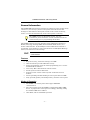
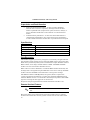
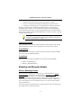
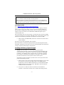
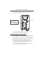
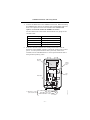
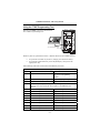
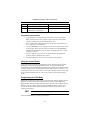
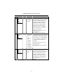
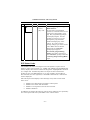
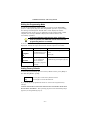
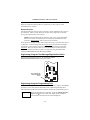
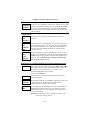
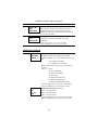
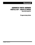
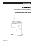
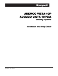
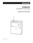
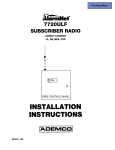
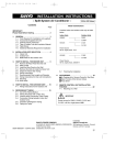
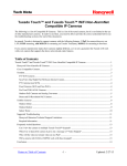
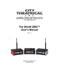
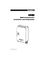
GSMX
GSM Communicator
Installation and Setup Guide
REG
TX/RX
FAUL
T
SIGN
AL
800-04432 9/09 Rev. B
Contents
General Information ........................................................................................... 1
Features.......................................................................................................... 1
Modes of Operation ........................................................................................ 1
Supervision and Fault Detection ................................................................... 2
Specifications.................................................................................................. 2
Data Encryption ............................................................................................. 2
Remote Services Features.............................................................................. 2
Testing the System......................................................................................... 3
Compatibility .................................................................................................. 3
Compliance ..................................................................................................... 3
Mounting and Wiring the Module ...................................................................... 3
Select a Mounting Location ........................................................................... 3
Activating the SIM .................................................................................... 4
Verifying Satisfactory Signal Strength ......................................................... 4
Mounting the Module on the Control Panel.................................................. 5
Mounting the Module on the Wall................................................................. 6
Programming the Module ................................................................................... 8
Using the AlarmNet Direct Website ............................................................. 8
Using the 7720P Programming Tool ............................................................. 9
Programming Conventions ..................................................................... 10
Using the Control Panel............................................................................... 10
Programming for ECP Mode........................................................................ 10
Programming for 4204 and Two-4204 Emulation Modes........................... 11
4204 Emulation Mode Options ............................................................... 11
Programming Options.................................................................................. 13
ECP Status Codes ........................................................................................ 18
Exiting the Programming Mode .................................................................. 19
Setting Factory Defaults.............................................................................. 19
Registering the Module..................................................................................... 20
Registering through the AlarmNet Direct Website .................................... 20
Remote Services....................................................................................... 21
Registering Using the Test Message/Registration Switch ......................... 21
Registering Using the Programming Tool................................................... 21
Replacing an existing module using the programming tool ....................... 22
Registering by Phone ................................................................................... 23
Diagnostic Commands ...................................................................................... 23
Module Identification Displays.................................................................... 23
GSM Status Displays ................................................................................... 24
Central Station Messages................................................................................. 26
Uploading and Downloading of Panel Data..................................................... 27
Glossary ............................................................................................................. 27
LED and Wiring Information ...................................Inside of Back Cover
GSMX Installation and Setup Guide
General Information
The GSMX GSM Communicator (also herein referred to as the module) easily
connects to your security system's control panel and sends alarms and
messages to AlarmNet for subsequent transfer to the central monitoring
station. It can be mounted directly on the control panel or remotely.
The GSMX requires an AlarmNet account. For new
installations, please obtain the account information from the
central station prior to programming this module.
The GSMX communicates with AlarmNet using GSM (Global System for
Mobile) technology utilizing GPRS (General Packet Radio Service) as a
means of data transfer. If the GPRS part of the GSM cellular network is
unavailable, it will attempt to send a transmission via SMS (Short Message
Service) also known as a text message.
ULC
SMS has not been evaluated for ULC central station
communication.
Features
•
•
•
•
•
•
•
•
Reports fire, burg, and status messages via GSM.
Internal antenna provides additional security.
Simple programming using the 7720P programming tool or via the
AlarmNet Direct website.
Uses 2 way ECP communication with the control.
Sends reports in Contact ID format.
Supports remote control of alarm system via Remote Services
Feature.
Allows uploading and downloading of control panel data via GSM.
Fully powered (primary and backup battery) from the control panel.
Modes of Operation
•
•
The GSMX is for control panels that support LRR-ECP
communication.
The control panel treats the GSMX as a Long Range Radio (LRR)
device, so program the control panel accordingly, including setting
the module’s LRR device address.
•
4204 Mode, and two 4204 Mode operation.
–1–
GSMX Installation and Setup Guide
Supervision and Fault Detection
•
•
Network communication failure – In the event the AlarmNet
network does not hear a supervisory message from the module
within a specified time (“Supervision” option, 24 hours, 30 days, or
none), AlarmNet notifies the central station of a communication
failure.
Communication path failure – In the event the module detects a
communication path failure, the control panel can be notified of a
trouble condition with the module after a specified time has elapsed.
Specifications
Dimensions
4 x 7 x 1.75 inches
Input Voltage
12VDC (powered via the ECP bus.)
Standby Current
30mA
Transmit Current
200mA (Average)
Transceiver Type
GSM/GPRS with internal antenna
Data Encryption
This module supports private key encryption. Private Key encryption means
that both the sender and the receiver know the KEY used to encrypt the data.
Each device produced by Honeywell is loaded with a unique identifier called a
MAC number, and a large random number or KEY. This KEY and MAC
number are also stored in the AlarmNet servers.
When a device contacts AlarmNet, it sends the MAC number followed by the
message that is encrypted using the KEY data. The server looks up the MAC
number and uses the KEY associated with it to decrypt the message.
The KEY uses 256-bit AES (Rijndael) encryption (which is required for
certain government installations). Further, the AlarmNet AES Encryption
Software Module Version 1.0 contained in the Honeywell products have NIST
approval. Listings for this approval can be found at
http://csrc.nist.gov/cryptval/aes/aesval.html Certification number 127.
Remote Services Features
UL
Remote Access and Multi-Mode have not been evaluated by
UL.
Honeywell offers secure web based services that enable users to remotely
monitor and control their security system. These web services enable users
to:
–2–
GSMX Installation and Setup Guide
•
•
•
Monitor and control their security system from a website
Receive e-mail and text message notifications of system events
Control the system and receive confirmations using text messages
Dealers can enroll their customers for "Remote Services" by using the
AlarmNet Direct website. Once enabled, the specific programming fields
associated with these features can be programmed into the communications
device either remotely using the AlarmNet Direct website or locally using the
7720P programming tool.
E-mail notification (Multi Mode) is intended as a convenience
for the user, and does not replace Central Station reporting of
critical events (alarms, troubles, etc.).
Testing the System
After installation the security system should be tested. Refer to the control
panel installation instructions for procedures to test the entire system.
Compatibility
The GSMX functions with any control panel that utilizes a Honeywell ECP
bus and supports Long Range Radio.
Compliance
This device has been tested by ETL to meet the following standards:
• UL985 – Residential Fire
• UL1023 – Residential Burg
Mounting and Wiring the Module
Select a Mounting Location
When choosing a suitable mounting location, understand that it must be
mounted indoors, and for best signal strength it should be mounted
vertically. Signal strength is very important for proper operation. For most
installations, mounting the unit on the control panel provides adequate
signal strength and we suggest that this method is tried first. Especially if
the control panel is not in a basement location or in an area that contains
large metal objects.
If the control panel location does not provide adequate signal strength, then
the module can be mounted remotely.
–3–
GSMX Installation and Setup Guide
NOTE: The SIM in the communications module must be ACTIVATED
first in order for signal strength to be determined.
Once the module is installed and programmed, it must be Registered
with AlarmNet. Registering activates the account with AlarmNet and
enables the security system's control panel to send reports.
Activating the SIM
Go to: https://services.alarmnet.com/AlarmNetDirect/
If you are not signed up for this service, click on “Dealer Signup” from the
login screen to set up your dealer account. You will be instructed how to
proceed upon completing the sign-up form. Only one sign-up per dealer is
required. Once an initial user is established, additional logins may be
created by that user.
Log in and follow the on-screen prompts. At this time only activate the SIM
so signal strength may be checked. DO NOT register the module at this time.
Please have the following information available to activate the SIM:
•
MAC number and MAC CRC (located on outside of box and on label
inside module).
You may log out of the AlarmNet Direct website.
Once the module is installed and programmed, it must be Registered with
AlarmNet. Registering activates the account with AlarmNet and enables the
security system's control panel to send reports.
Verifying Satisfactory Signal Strength
NOTE: In this procedure you will temporarily power up the
communications module to check for satisfactory signal strength. You
can power it from a 12V battery or from the control panels AUX PWR
terminals. In buildings where reception may be a problem, powering
from a battery would allow the module to be portable. The following
procedure assumes the control panel will be used for power.
If satisfactory signal strength is present at the control panel that is the
preferred mounting location.
1.
Ensure power to the control panel (both AC and battery) is off. Open
the enclosure and connect the ECP cable to the GSMX module.
Temporarily attach the Black and Red wires to the GND and AUX
PWR terminals of the control panel. DO NOT connect the Yellow
and Green wires at this time.
2.
Turn power on and wait about one minute for the module to
initialize. Position the module near a suitable mounting position.
–4–
GSMX Installation and Setup Guide
Verify the SIGNAL LED (green) lights steady. This indicates
satisfactory signal strength.
Hole Cap
SIGNAL LED (green)
ON - Satisfactory Signal
BLINKING - Marginal Signal
GSMX-001-V0
OFF - Unsatisfactory Signal
3.
Verify the SIGNAL LED (green) remains steady for a few minutes,
then mark that mounting position. Turn power off.
Mounting the Module on the Control Panel
1.
Ensure power to the control panel (both AC and battery) is off, then
remove the knockout on the top right of the control panel cabinet.
2.
Open the GSMX cover. Remove the Hole Cap attached to the plastic
(trim as necessary), and snap it into the top opening of the enclosure.
3.
Remove the bottom knockout on the GSMX enclosure for the
threaded mount. Then install the threaded mount so it snaps into
the plastic retaining tabs. Mount the GSMX assembly on the
cabinet's knockout, and fasten with the locking nut.
4.
Connect the ECP cable to the GSMX circuit board and thread the
wires through the threaded mounting adapter.
–5–
GSMX Installation and Setup Guide
ECP Cable
Control Panel
Cabinet
To ECP Bus on control
panel circuit board.
PANEL DATA IN - Green
GND - Black
AUX PWR (+12V) - Red
PANEL DATA OUT - Yellow
GSMX-005-V0
Threaded Mount
5.
Refer to the installation guide for the control panel, and complete the
ECP cable wiring.
6.
Secure the wiring with ties as necessary.
Mounting the Module on the Wall
1.
Ensure power to the control panel (both AC and battery) is off, then
remove a suitable knockout on the top or side of the control panel
cabinet.
NOTES:
• If in the wall wiring will be used, route the wiring through the
communications module's rear wiring access hole.
• If surface mounted wiring will be used, remove the
communications module's bottom knockout and use that to route
the wiring.
2.
Open the GSMX cover. Remove the Hole Cap attached to the plastic
(trim as necessary), and snap it into the top opening of the enclosure.
3.
Secure the enclosure to the wall using both mounting holes.
–6–
GSMX Installation and Setup Guide
4.
Connect the ECP cable to the GSMX circuit board. When mounting
the GSMX off the cabinet, the length of the supplied ECP cable will
have to be spliced to a four-wire extender cable. Ensure the
splices are located within the GSMX's enclosure.
Use the table below to determine the minimum wire gauge for the
extender cable.
Minimum Wire Gauge
75 ft (23m)
#20
120 ft (37m)
#18
170 ft (52m)
#16
270 ft (82m)
Route the wires through the rear wiring access hole or bottom
knockout on the GSMX. Continue routing the wiring to the control
panel. A control panel knockout that is presently used can be
utilized, however DO NOT utilize a control panel knockout that is
being used for primary power.
Mounting
Hole (2)
Wiring
Access
Hole
Hole
Cap
ECP Cable
To ECP Bus on control
panel circuit board.
PANEL DATA IN - Green
GND - Black
AUX PWR (+12V) - Red
PANEL DATA OUT - Yellow
–7–
GSMX-006-V0
5.
Distance from Control Panel
#22
GSMX Installation and Setup Guide
6.
Refer to the installation guide for the control panel, and complete the
ECP cable wiring.
7.
Secure the wiring with ties as necessary.
Programming the Module
The GSMX requires an AlarmNet account. For new installations, please obtain the account information from the central
station prior to programming this module.
You can program the communications module by one of the following
methods:
•
Using the AlarmNet Direct website.
•
Using the 7720P Programming Tool.
•
Using the control panel's programming mode (for panels that
support this option) to access the communication module's
programming.
NOTE: The prompts in this document reflect use of the 7720P
Programming Tool.
Using the AlarmNet Direct Website
To program the module via the website (if you are already signed up for this
service), go to: https://services.alarmnet.com/AlarmNetDirect/
If you are not signed up for this service, click on “Dealer Sign-Up" and follow
the instructions. Log in and follow the on-screen prompts. Please have the
following information available when programming the module:
•
Primary City ID (two-digit number), obtained from your monitoring
station.
•
Primary Central Station ID (two-digit number), obtained from your
monitoring station.
•
Primary Subscriber ID (four-digit number), obtained from your
monitoring station.
•
Communications module MAC ID and MAC CRC number (located on
the outside of box and on a label inside the module).
After programming is complete, the module must be registered. Refer to the
Register the Module topic.
–8–
GSMX Installation and Setup Guide
Using the 7720P Programming Tool
Ensure the GSMX is powered, and connect
the 7720P Programming Tool.
GSMX-007-V0
TEST MESSAGE/REGISTRATION
Switch
Each key has two possible functions; a Normal function and a Shift function.
•
To perform a Normal key function, simply press the desired key.
•
To perform a Shift function, press the [shift] key, then press the
appropriate key.
The following table lists each normal and shift key function.
7720P Normal and Shift Key (shift LED lit) Functions
KEY
NORMAL KEY FUNCTION
SHIFT + KEY FUNCTION
BS/ESC
[BS]: Press to delete entry
[ESC]: Press to quit program mode;
also can reset programming
defaults.*
↓/↑
[↓]: Scroll down programming
[↑]: Scroll up programming
N/Y
[N]: Press for "NO" answer
[Y]: Press for "YES" answer
SHIFT
Press before pressing a SHIFT key function. Will light SHIFT LED. LED
goes out once a key is pressed. Press again for each SHIFT function
desired.
1/A
[1]: For entering the number 1
[A]: For entering letter A
2/B
[2]: For entering the number 2
[B]: For entering letter B
3/C
[3]: For entering the number 3
[C]: For entering letter C
4/D
[4]: For entering the number 4
[D]: For entering letter D
5/E
[5]: For entering the number 5
[E]: For entering letter E
6/F
[6]: For entering the number 6
[F]: For entering letter F
7/S
[7]: For entering the number 7
[S]: For entering letter S
8/T
[8]: For entering the number 8
[T]: For entering letter T
9/X
[9]: For entering the number 9
[X]: For entering letter X
–9–
GSMX Installation and Setup Guide
SPACE
[SPACE]: For scrolling option list
No SHIFT function
0
[0]: For entering the number 0
No SHIFT function
#/ENTE
R
[#/ENTER]: Starts programming
mode; Press to accept entries
No SHIFT function
* Active only when the "Exit Programming Mode" prompt is displayed.
Programming Conventions
•
Programming is accomplished by answering a series of prompts.
Most prompts require only a [Y]es or [N]o response, while others
require a numerical response (ID numbers, etc.).
•
The current value is displayed on the second line in parentheses ( ).
A "?" indicates an invalid entry.
•
Use the [ENTER] key to accept the current entry and proceed to the
next prompt. If the entered value is invalid, pressing [ENTER] redisplays the prompt; the next prompt is not displayed until a valid
answer is entered.
•
Use the up/down arrow keys to scroll through the programming
prompts without changing any values.
•
Press the [ESC] key to go to the end of the list of prompts.
Using the Control Panel
Some control panels support programming of the communications module
through the control panel programming mode. If using this method of
programming, only the ECP Mode programming options are available. Other
"mode" prompts will not be displayed, and the mode cannot be changed. For
a description of key functions on the control panel keypad, and how they map
to the 7720P programming tool, refer to the control panel's Programming
Guide.
Programming for ECP Mode
ECP mode enables the control panel to communicate with the module via the
ECP bus. Control panels that support this bus and have the LRR (Long
Range Radio) enabled, send Contact ID format alarms to the module over the
ECP bus. Not all control panels support the LRR interface on ECP, so be
sure to check the control panel's Installation and Setup Guide to see if it
supports this feature.
ULC
Only ECP Mode has been approved for ULC installations.
Press the [ENTER] key to begin programming.
– 10 –
GSMX Installation and Setup Guide
NOTE: The central station can remotely block access
to local device programming. If this has been done,
prompt on the right appears.
Access to Prog
Mode Denied
The default programming values for each prompt are shown in parentheses
in the PROMPTS column. Further, the table below shows all the prompts for
this programming mode. Depending on your answers, unnecessary prompts
will be bypassed and you will advance to the next appropriate prompt.
Programming for 4204 and Two-4204 Emulation Modes
In this mode the communications module emulates a 4204 module (or two)
and appears to the control panel as a 4204 module. If two 4204s are enabled
in the communications module, it acts as two 4204s using consecutive device
addresses.
The compatible Honeywell VISTA series or First Alert control panel sends
data (triggers) to the communications module as if it were a 4204 module.
(The control panel must be configured to recognize one or two 4204 relay
modules accordingly.) On VISTA-32FB (or higher) control panels and First
Alert equivalents, addresses 6 and 13 should not be used when the secondary
4204 is enabled. Messages are sent in ADEMCO High-Speed format.
NOTE: See your control panel Installation and Setup Guide for the number
of 4204 modules supported.
4204 Emulation Mode Options
For control panels that do not support LRR-ECP communication, the 4204
Emulation modes provide a means of sending up to eight unique reports
based on defined system conditions. In 4204 mode, the communications
module functions as a logical 4204 Relay Module, where each relay number,
referred to in the module as zone number, can be programmed to send a
report based on the output function programmed in the control for that relay.
Each relay-zone can also be programmed to send a restore message of the
reported condition, can be set to delay transmission of messages, and can be
programmed to send reports only when a conditional zone is triggered
(armed).
In single 4204 mode, the module supports up to four relay-zones. In Two4204 mode, the module functions as two 4204 modules, supporting up to eight
relay-zones. Refer to the following table.
– 11 –
GSMX Installation and Setup Guide
4204 Relay Outputs map to zones
First 4204 Zones (device
address entered in Prompt 15):
Second 4204 Zones (device address
entered in Prompt 15, plus 1):
Relay 1 = Zone 1
Relay 2 = Zone 2
Relay 3 = Zone 3
Relay 4 = Zone 4 or conditional
zone trigger if “report only if
armed” is selected in any zone 1-3
when using single 4204 mode.
NOTE: Zone 4 status is not
reported when being used as the
conditional (armed) trigger zone.
Relay 1 = Zone 5
Relay 2 = Zone 6
Relay 3 = Zone 7
Relay 4 = Zone 8 or conditional zone
trigger if “report only if armed” is
selected in any zone 1-7 when using
Two-4204 mode.
NOTE: Zone 8 status is not reported
when being used as the conditional
(armed) trigger zone or if tamper
reporting is enabled.
When using the module in 4204 Emulation Mode, DO NOT enable the LongRange Radio module in control panel programming. Instead, enable 4204
relay module address(es) and program the appropriate relay activation
functions for the relay-zones being used. In some control panels, it is called
“relay programming” and in others it is called “output device programming.”
It is recommended that “close and stay closed” (usually choice 2) action is
selected. Selection of momentary activation will cause the communications
module to generate an alarm and NOT a restore, even if the module is
programmed to send a restore for the given zone.
In 4204 mode, messages are reported in ADEMCO High-Speed format. Zone
alarms
(status 7) are reported with “1” (alarm) or “3” (restore) displayed in the zone
position for the respective zone (e.g. alarm on zone 2: 5155 5555 7; restore
5355 5555 7). A supervision fault trouble message is automatically sent if the
module detects no activity on its connection to the control. The message is:
5555 5515 5; restore message is: 5555 5535 5.
– 12 –
GSMX Installation and Setup Guide
Programming Options
NOTE: The default programming values are listed in the prompts below.
PROMPTS
1
Strt Prog
Mode?
ENTRY
OPTIONS
DESCRIPTION
[Y], [N]
Enters programming mode.
(Y/N)_
2
Enter
Password
[0-9, A-F,
N, S, T, X,
Y]
If a password has been previously
assigned, this prompt appears.
Enter a 4-digit password
(0-9, A-F, N, S, T, X, Y).
The next prompt appears.
3
Program
Device?
[Y], [N]
To begin programming the
module, press [Y] and go to
Prompt 9: "Device Mode."
To create a password if none has
been assigned, press [N] and go to
Prompt 4: "Create Password?."
To change an existing password,
press [N] and go to Prompt 5:
"Change Password?."
[Y], [N]
Passwords can be used to protect
account and programming
information.
If no password has been assigned,
this prompt appears after
pressing [N] at the "Program
Device?" prompt.
If a password is desired, press [Y]
and go to Prompt 6: "Enter
Password."
(Y/N)_
4
Create
Password?
(Y/N)_
– 13 –
GSMX Installation and Setup Guide
PROMPTS
5
Change
Password?
ENTRY
OPTIONS
DESCRIPTION
[Y], [N]
If a password has already been
assigned, this prompt appears
after pressing [N] at the
"Program Device?" prompt.
Press [Y] if you want to change
the password.
NOTE: To clear an existing
password, without entering a new
one, answer [Y] to the "Change
Password?" prompt, then press
the [Enter] key when prompted
for the new password and its
confirmation.
(Y/N)_
6
Enter
Password
[0-9, A-F,
N, S, T, X,
Y]
This prompt is displayed if [Y]
was pressed in Prompt 4 or 5.
Enter a 4-digit password
(0-9, A-F, N, S, T, X, Y).
7
Verify
Password
[0-9, A-F,
N, S, T, X,
Y]
Re-enter the password as
confirmation.
If the password doesn't match the
first entry, the following is
displayed followed by the "Exit
Prog. Mode?" prompt:
Verify Not OK
PSWD not created
Otherwise, the "Exit Prog. Mode?"
prompt is displayed directly.
8
Exit Prog.
Mode?
[Y], [N]
[ESC]
Exits program mode.
Press [N] to go back to Prompt 3.
Press [ESC] to load factory
defaults.
Refer to the Exiting the
Programming Mode topic.
• ECP
• 4204
Emu
• Two
4204s
Press the [space] key to scroll
through the modes of operation.
Press [ENTER] to select the
desired mode.
(Y/N)_
9
Device
Mode
(ECP)_
– 14 –
GSMX Installation and Setup Guide
PROMPTS
ENTRY
OPTIONS
DESCRIPTION
NOTE: Prompts 10 and 11 only appear if the Multi-Mode feature has been enabled.
Setting up E-mail Notifications (Multi-Mode feature)
NOTE: E-mail notification is intended as a convenience for the user, and does
not replace Central Station reporting of critical events (alarms, troubles, etc.).
Users can receive e-mail notification of system events by using the Multi-Mode
feature. The following items must be met to use this feature.
•
The Multi-Mode feature must be enabled during account programming on the
AlarmNet Direct website by selecting "Enabled" at Multi-Mode prompt.
•
The GSMX will emulate one or two 4204 relay modules to accommodate system
events that are programmed in the control panel. When programming the
GSMX, at prompt #10, choose 4204-Sourced so the user can be notified of up to
four events, or choose 2-4204-Sourced so the user can be notified of up to eight
system events.
•
The 4204 relay events used to trigger email notifications are defined on the
Honeywell Total Connect website, and must correspond to outputs (relays)
programmed in the control panel through Output Device programming.
•
The Multi-Mode address selected at prompt #11 in the GSMX (or at the
AlarmNet Direct website) must match the address of a 4204 relay module
enabled in the control panel (although you don’t actually connect a module).
If using “2-4204-sourced,” the address of the second module is automatically
assigned the next device address after the first 4204. Make sure that address is
also enabled in the control panel.
10
Multi Mode
(Disabled)_
11
Multi Mode
Addr
• Disabled
• 4204
Sourced
• 2-4204
Sourced
Enable if you want system events
sent by e-mail to the user. Select
"4204 Sourced" to send up to four
events, or "2-4204 Sourced" to
send up to eight events.
Disable for normal alarm
processing and go to Prompt 12
"Primary City ID" prompt.
[01-30]
This address must be
programmed if using the MultiMode (e-mail notification)
feature. The device address must
be unique from the normal LRR
Device Address and the Keypad
Address used for Remote Access
or Direct Wire downloading.
The address used must also be
enabled as a 4204 relay module in
Vista and First Alert control
panels.
(12)
– 15 –
GSMX Installation and Setup Guide
PROMPTS
ENTRY
OPTIONS
DESCRIPTION
NOTE: Account information is provided by the central station administrator.
12
Primary City
ID
[01-99]
Enter the 2-digit primary city ID,
01-99 (decimal).
[01-FE]
Enter the 2-digit primary central
station ID number, 01-FE (HEX).
[00019999]
Enter the 4-digit subscriber
account number, 0001-9999
(decimal).
[01-30]
The module communicates with
the panel as a Long Range Radio
(LRR) device. Enter ECP device
address.
NOTE: When programming the
control, enable the LRR output.
(??)_
13
Primary CS
ID
(??)
14
Primary Sub
ID
(????)
15
Device
Address
(03)_
Setting up the Remote Access Feature
Remote Access enables the user to control the security system using a web browser.
This feature must be configured at the AlarmNet Direct website as follows:
• Remote Access must be enabled by selecting "Enabled" at the Remote Access
prompt.
• A keypad address must be enabled in the GSMX in order for the module to
communicate with the control panel.
• At the “Keypad Type” prompt, select the appropriate Keypad.
16
Remote
Access
Y/N
[Y], [N]
Press [Y] to allow the end user to
access their system via a website.
Availability of this service is
controlled by the dealer via the
web-based programming tool on
the AlarmNet Direct website.
[01-30]
NOTE: This prompt will only
appear if the Remote Access
feature has been enabled.
Must be programmed if using the
Remote Access feature. Enter the
appropriate device address.
(N)_
17
Keypad
Address
(28)_
– 16 –
GSMX Installation and Setup Guide
PROMPTS
18
Supervision
(24
Hours)_
19
Old Alarm
Time
(10
Minutes)_
20
GSM Flt
Time
(00 mins)_
ENTRY
OPTIONS
• 30 Day
• 24 Hour
• None
• 10
Minutes
• 15
Minutes
• 30
Minutes
• 1 Hour
• 2 Hours
• 4 Hours
• 8 Hours
• 12 Hours
• 24 Hours
[01-99]
[00] = not
used
– 17 –
DESCRIPTION
The AlarmNet network must hear
at least one supervisory message
from the module during this
supervision period; otherwise,
AlarmNet notifies the central
station that a communication
failure has occurred. (If the
supervision period is changed
after registration, you must reregister the module.)
Press the [space] key to scroll
through choices.
UL NOTE: Must be 24 hour.
The old alarm time sets how long
an undeliverable alarm is retried
for delivery to the central station.
If the message is not validated, it
is retried until the old alarm time
is reached or the message is
validated.
Press the [space] key to scroll
through choices.
UL NOTE: Must be 10 minutes.
In the event the module detects a
communication path failure,
enter the time delay (in minutes)
before the module notifies the
control panel with a trouble
message. The control panel can
then notify the central station.
UL NOTE: Must be one (01)
minute.
GSMX Installation and Setup Guide
PROMPTS
21
ENTRY
Review?
Y/N
OPTIONS
[Y] =
review
[N] = exit
DESCRIPTION
Reviewing Programming
Mode Entries
To review the programming
options (to ensure that the correct
entries have been made), press
[Y]. The programming prompts
are displayed again. Use the
up/down arrow keys to scroll
through the program fields
without changing any of the
values. If a value requires
change, simply type in the correct
value. When the last field is
displayed, the “REVIEW?”
prompt again appears.
To exit the programming
mode, press [N] in response to
the "REVIEW?" prompt, and refer
to Exiting Programming Mode
topic.
ECP Status Codes
The GSMX sends status messages to the control panel to report various
failures. Some control panels, (e.g., VISTA-10P, VISTA-15P and VISTA-20P
Series) display these status codes on the keypad as “LngRng Radio” followed
by a 4-digit code. Commercial panels can supervise the communicator
module by way of its ECP address, ex: 03. For example, if the module is
disconnected, if it's not registered, or the SIM is deactivated, a "Check 803"
will be displayed.
The control panel will display a fault message if any of the events listed
below occur.
•
•
•
•
Module lost communications with the control panel.
Module lost contact with AlarmNet.
Module is not registered; account not activated.
Module shutdown.
In addition, the Contact ID codes for some of these conditions are reported by
the control panel and sent by AlarmNet to the central station.
– 18 –
GSMX Installation and Setup Guide
Exiting the Programming Mode
To exit the programming mode, press [N] in response to the "REVIEW?"
question. Then press [Y] to the "Exit Prog Mode?" question. Upon exiting,
the message “Checking Root File TX Path” will be displayed, and the
configuration file at the server is updated to log the changes made. When
complete, the message "DONE" is displayed to indicate the file was
successfully uploaded.
If critical configuration changes were made, such as the
mode of operation, the GSMX will reset to ensure that the
programming features are enabled.
If the file is not successfully uploaded, one of the following prompts will be
displayed. Follow the steps shown below until the upload is successful.
Display
Cannot Upload
Try Again?
Y/N_
Failed to Update
Root File!
Description
What to do
GSM
Communicator has
not yet initialized.
Wait for SIGNAL (green) LED to
be lit.
Press [Y].
Network problem,
or you answered
"N" to "Cannot
Upload Try Again?"
prompt.
Initiate the Force Server Update
command by pressing the [0] key.
Setting Factory Defaults
To reset the programming options to factory-default values, press [ESC] at
the "Exit Prog Mode?" prompt.
Set Default?
Y/N_
Press [Y] to reset factory default values.
Press [N] to cancel this function.
If you press [Y], all programmed values are reset to the original factory
settings.
PLEASE NOTE THAT THIS WILL ERASE ANY PASSWORD THAT MAY
HAVE BEEN ENTERED. After pressing [Y], the Create Password prompt
appears (see Programming step 4).
– 19 –
GSMX Installation and Setup Guide
Registering the Module
Once you have programmed the GSMX, it must be registered to enable the
AlarmNet account. Registering the communications module activates the
account with AlarmNet and enables the security system's control panel to
send reports. You can register by using one of the following methods:
•
AlarmNet Direct website
•
7720P Programming Tool
• Test Message/Registration switch • Phone
The top display LED will indicate the module's registration status as follows:
(Refer to the Summary of Connections topic.)
LED
Indication
REG
(green)
ON – Module is NOT registered with AlarmNet.
OFF – Module is registered with AlarmNet.
You can monitor the registration process by viewing the display LEDs. The
TX/RX (yellow) LED and the REG (green) LED will blink slowly in unison
while registration is in progress.
When the registration successfully completes, the GSMX enters a normal
operating mode; the REG (green) LED goes out and the TX/RX (yellow) LED
is lit to indicate that the power-on / reset message is waiting to be sent. This
message will appear at the receiving station as “E339 803”. The description
may read “Trouble – Exp. Mod. Reset”. If registration is not validated within
90 seconds, the GSMX times out, and the REG (green) LED will be lit solid.
Registering through the AlarmNet Direct Website
To register the module via the website, go to:
https://services.alarmnet.com/AlarmNetDirect
Log in and follow the on-screen prompts. If you are not signed up for this
service, click on “Dealer Signup” from the login screen to create an account.
You will be instructed how to proceed upon completing the sign-up form.
Only one sign-up per dealer is required. Once an initial user is established,
additional logins may be created by that user.
NOTE: Central Stations can sign up by contacting AlarmNet Support at
800-222-6525 and selecting option 1.
Please have the following information available:
•
•
•
•
Primary City ID (two-digit number).
Primary Central Station ID (two-digit hexadecimal number).
Primary Subscriber ID (four-digit number).
MAC ID and MAC CRC number (located on outside of box and on
label inside module).
– 20 –
GSMX Installation and Setup Guide
After the communications module is registered, you may log out of the
AlarmNet Direct website.
Remote Services
The dealer/installer will set up the customer account and define the events to
be notified of. These events match the output relay triggering events that
were programmed in the control panel.
NOTE: At the AlarmNet Direct website, refer to the online "AlarmNet
Direct User Guide" for information on configuring the hardware and
creating a Total Connect web account for the customer.
Once the dealer assigns a login name and password, the customer will receive
a “Welcome” e-mail message with their login name along with some helpful
information. The customer will receive another e-mail message with their
password. They will then be able to receive notifications, and access their
system via the Total Connect website or using their cell phone/PDA that
supports GSM/GPRS and Text Messaging (SMS).
Registering Using the Test Message/Registration Switch
Initiate the registration sequence by clicking the TEST
MESSAGE/REGISTRATION switch three times.
GSMX-009-V0
TEST MESSAGE/
REGISTRATION
Switch
Registering Using the Programming Tool
The interactive registration feature allows the installer to register the GSMX
through a series of keyboard commands on the 7720P Programming Tool.
This method of registration lets the installer monitor the registration process.
Registering
…
Once the installation is complete, press the [Shift] plus the
up arrow [↑] on the 7720P. The registration message is
sent and the unit waits for the acknowledgment.
– 21 –
GSMX Installation and Setup Guide
Registration
SUCCESS
If this is a new installation and the city, central station, and
customer numbers have been correctly entered, the GSMX
is registered and this message is displayed. The GSMX is
now in full service and available for alarm reporting to the
central station.
Possible Errors
Registration
BAD
Displayed if no response to the registration request is
received.
Timed Out
Registration
BAD
Pri Sub ID
BAD
Registration
BAD
Pri ID –
Need PIN
Indicates the city, central station, or customer number for
the labeled account(s) is not accepted. The ID information
was either entered in error, or the central station failed to
pre-authorize programmed ID numbers with AlarmNet
customer service.
Displayed if this is a repair/replacement, or an error was
made in programming the Primary account information of
GSMX for an existing account. This prompt appears for 2
seconds. See the Replacing an existing module using
the programming tool topic.
Replacing an existing module using the programming tool
Enter PIN#
This prompt appears after pressing the down arrow [↓] on
the 7720P. Enter a 4-digit alphanumeric PIN number
provided by your central station, your dealer or an
authorized AlarmNet representative.
Press the [ENTER] key.
Registering
…
The registration message is sent and the unit waits for
acknowledgement.
Registration
If the PIN is valid, the new GSMX is registered and the old
unit unregistered. Additionally, AlarmNet sends a
substitution alarm to the central station.
SUCCESS
Registration
BAD
If you entered an invalid PIN, the appropriate message is
displayed depending on which account number is being
replaced (see above for exact wording). The registration
process is repeated.
NOTE: Each attempt causes a substitution alarm to be
sent to the central station.
– 22 –
GSMX Installation and Setup Guide
Registering by Phone
You can register the module by calling the AlarmNet Support at 1-800-2226525 (Option 1). You will need the following information:
•
MAC ID and CRC (located on outside of box and on label inside
module).
•
Subscriber information (provided by the central station), including a
city code, CSID, and subscriber ID.
•
When instructed to do so, triple-click the Test
Message/Registration switch to complete the registration.
Diagnostic Commands
The 7720P programming tool can be used to view the connectivity settings
and options. To invoke diagnostic commands; such as [A], [B], [C], etc., the
[shift] key MUST used. For example, [shift] + [A] displays the software
revision.
Module Identification Displays
[A]
[B]
7845GSM
x.x.xx
mm/dd/yy
Software Revision
MAC
xxxxxxxxxxxx
MAC CRC
yyyy
MAC Address
“xxxxxxxxxxxx” indicates the GSMX's unique
identification number.
"yyyy" indicates the MAC CRC number. These numbers
are found on the label on the module, as well as the label
on the box.
Press the [Space] key to go to the next field.
Press the [BS] key to go to the previous field.
SCID xxxxx
xxxxx
xxxxx
xxxxx
SCID Display
IMEI
xxxxxxxx
xxxxxx
x
IMEI Display
"x.x.xx" indicates the installed software revision.
Mm/dd/yy indicates month, day and year of the
revision.
Displays the identification number assigned to the
SIM card (SCID) in this device.
Press the [Space] key to go to the next field.
Press the [BS] key to go to the previous field.
Displays the identification number assigned to the
GSM module in this device.
Press the [Space] key to get the MAC Address.
Press the [BS] key to go to the previous field.
– 23 –
GSMX Installation and Setup Guide
[C]
[D]
Mon 01 Jan
2001
05:48:39 am
Time
Encryption
Test
AES Passed!
Encryption Test
Retrieves the current date and time from the
AlarmNet network in Greenwich Mean Time
(GMT). This display confirms that the module is
in sync with network.
Performs a self-test of the AES encryption
algorithm.
Press the [Space] key to go to the next field.
Press the [BS] key to go to the previous field.
GSM Status Displays
[E]
PriRSSI
GPRS REG
-xxxdbm x
x
GSM Status Display Screen 1
Cntry Netw
LAC
xxx xxx
xxxxx
GSM Status Display Screen 2
Cntry – Country Code
Netw – Network Code
LAC – Local area code
Press the [Space] key to get to the next screen.
Press the [BS] key to go to the previous field.
PriRSSI – Primary Site RSSI level in dBm
GPRS – GPRS Service availability where “x” can
be:
“Y” if GPRS is available
“N” if GPRS is Not available
REG – Registration status from communicator
module
where “x” can be:
N – Not Registered
H – Registered Home
S – Searching
D – Registration Denied
R – Registered Roaming
? – Unknown Registration State
Press the [Space] key to go to the next screen.
Press the [BS] key to go to the last screen.
– 24 –
GSMX Installation and Setup Guide
[S]
Cell BaseSt
Chan
xxxxx x
xxx
GSM Status Display Screen 3
Cell – Base Station ID
BaseSt – Base Station Antenna Sector
Chan – Control Channel in use
Press the [Space] key to go to the next screen.
Press the [BS] key to go to the previous field.
Second Site
RSSI
-xxxdbm
GSM Status Display Screen 4
Secondary GSM Site RSSI level in dbm.
Press the [Space] key to go to the GSM Status
Display Screen 1.
Press the [backspace] key to go to the previous
field.
ECP
ECP Mode
Displays the mode of operation and system fault
status.
Flt – Represents communicator faults:
OK = Normal, No fault.
G = No network connectivity over GSM and fault
time has expired.
g = No network connectivity over GSM and fault
time has NOT yet expired.
Flt
OK
[T]
Test Msg
Sent
Test Alarm
Sends a Test alarm to AlarmNet. Functional for
a registered GSMX only. If the device is not
registered, a message is displayed indicating
that the command cannot be executed.
[X]
Reset CPU
Y/N
Reset the GSMX.
Pressing [N] returns to normal mode.
Pressing [Y] resets the device.
[Shift]
[↑]
(UP
arrow)
Registering
…
Registration
Registers a programmed GSMX with AlarmNet.
[↓]
(DN
arrow)
Enter PIN#
Registration with PIN for Replacement
Module
Registers a replacement GSMX with AlarmNet,
once programmed, using the existing PIN #.
– 25 –
GSMX Installation and Setup Guide
[0]
Force Upload of Configuration File to
Server
Pressing [Y] will force the device to upload its
entire configuration file to the server.
Pressing [N] cancels the operation.
NOTE: If the GSM module is not initialized
when you enter this command, the following
screen will be displayed:
Force
Server
Update?
Y/N
Cannot Upload
Try Later! _
Wait for the SIGNAL (green) LED to light,
indicating the GSM module has completed its
initialization, and try again.
[ENTER] Strt Prog
Mode?
Y/N_
Enter Program Mode
Press [Y] to enter program mode; otherwise,
press [N].
Central Station Messages
The following messages are sent to the Central Station by AlarmNet for the
conditions listed below.
Alarm Condition
Power On / Reset
(xx=device address)
ECP Supervision
Communication Path
Supervision
Test
ECP Mode
Alarm Code Restore Code
E339 C08xx
E355 C0000
E350 C0951
4204 Modes
Alarm Code
Restore Code
5551 5555 6
R355 C0000
R350 C0951
5555 5555 9
5555 5515 5
5555 5551 5
5555 5535 5
5555 5553 5
5555 5555 9
NOTE: The control panel sends its own general code (E353) for a trouble
condition.
– 26 –
GSMX Installation and Setup Guide
Uploading and Downloading of Panel Data
NOTE: For UL, downloading may only be performed if a technician is
at the site.
The GSMX can be used to provide high-speed up/downloading to control
panels (that support this feature) over the GPRS network via ECP
communication. This allows site maintenance independent of central station
monitoring, and modification to sites globally. Refer to the control panel's
Installation and Setup Guide for detailed information.
• The GSMX cannot be used for Direct-Wire downloading.
Glossary
AES
CRC
DACT
ECP
GPRS
GSM
IMEI
MAC ID
Advanced Encryption Standard
Cyclic Redundancy Check used to confirm validity of MAC ID.
Digital Automated Communications Terminal
Enhanced Console Protocol, is a proprietary bus used in
Honeywell control panels to communicate with keypads and
peripheral devices. It uses four wires; power, ground, data in,
data out.
General Packet Radio Service.
Global System for Mobile communications, which is an
international standard for digital mobile phone systems used
for cellular communication.
International Mobile Equipment Identity number.
Media Access Code, this is a unique address assigned to every
network communications device. Typically it is located on
the module label, and on the box.
– 27 –
NOTES
LED and Wiring Information
LED
DESCRIPTION
REG
(green)
ON – Module is NOT registered with AlarmNet.
OFF – Module is registered with AlarmNet.
FAST BLINK – Download session with Compass in progress.
SLOW BLINK – In unison with yellow LED – Registration in progress.
TX/RX
(yellow)
ON – Message transmission pending.
QUICK PERIODIC BLINK - Normal
FAST BLINK – Message waiting for network ACK.
SLOW BLINK – In unison with green LED – Registration in progress.
FAULT
(red)
ON – No contact with network.
OFF– Normal.
SLOW BLINK – Loss of communication with the panel (ECP fault).
FAST BLINK – No network contact AND loss of communication with the
control panel.
SIGNAL
(green)
ON – Minimum required signal strength is present.
BLINKING – Marginal signal strength is present.
OFF – Installation is not recommended.
ALL
FAST BLINK – Hardware Error.
TRANSMIT
(Blinks during transmisson.)
REG
TX/RX
FAULT
SIGNAL
TEST MESSAGE/REGISTRATION
Switch
To ECP Bus on control
panel circuit board.
PANEL DATA IN - Green
GND - Black
AUX PWR (+12V) - Red
PANEL DATA OUT - Yellow
GSMX-010-V0
ECP Cable
FEDERAL COMMUNICATIONS COMMISSION (FCC) STATEMENTS
The user shall not make any changes or modifications to the equipment unless authorized
by the Installation Instructions or User's Manual. Unauthorized changes or modifications
could void the user's authority to operate the equipment.
CLASS B DIGITAL DEVICE STATEMENT
NOTE: This equipment has been tested and found to comply with the limits for a Class B
digital device, pursuant to part 15 of the FCC Rules. These limits are designed to provide
reasonable protection against harmful interference in a residential installation. This
equipment generates, uses and can radiate radio frequency energy and, if not installed and
used in accordance with the instructions, may cause harmful interference to radio
communications. However, there is no guarantee that interference will not occur in a
particular installation. If this equipment does cause harmful interference to radio or television
reception, which can be determined by turning the equipment off and on, the user is
encouraged to try to correct the interference by one or more of the following measures:
• Reorient or relocate the receiving antenna.
• Increase the separation between the equipment and receiver.
• Connect the equipment into an outlet on a circuit different from that to which the receiver
is connected.
• Consult the dealer or an experienced radio/TV technician for help.
INDUSTRY CANADA (IC) STATEMENTS
This device complies with RSS210 of Industry Canada. Operation is subject to the following
two conditions: (1) This device may not cause harmful interference, and (2) This device
must accept any interference received, including interference that may cause undesired
operation.
This Class B digital apparatus complies with Canadian ICES-003.
Cet appareil numérique de la classe B est conforme à la norme NMB-003 du Canada.
DOCUMENTATION AND ONLINE SUPPORT
For the latest documentation and online support information, please go to:
http://www.security.honeywell.com/hsc/resources/MyWebTech/
WARRANTY
For the latest warranty information, please go to:
http://www.security.honeywell.com/hsc/resources/wa/
2 Corporate Center Drive, Suite 100,
P.O. Box 9040, Melville, NY 11747
Copyright © 2009 Honeywell International Inc.
www.honeywell.com/security
Ê800-04432zŠ
800-04432 9/09 Rev. B