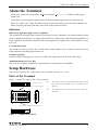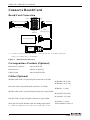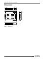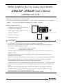
1
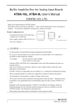
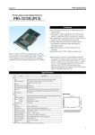
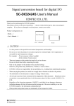
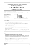
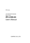
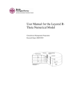
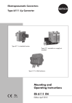
Buffer Amplifier Box for Analog Input Boards
ATBA-32F, ATBA-8F User’s Manual
CONTEC CO.,LTD.
Thank you for purchasing the CONTEC product.
The product consists of the items listed below. Check, with the following list, that your package is
complete. If you discover damaged or missing items, contact your retailer.
Product Configuration List
CN1 (EXT.SIGNALS)
DC5V
User’s Manual
- Power supply connector (MC1,5/3-ST-3,5)…1
- This User’s Manual…1
- Warranty Certificate …1
- Serial number label …1
FG V- V+
- Termination Panel (One of the following)…1
[ATBA-32F or ATBA-8F]
CN2 (BOARD/CARD)
User’s Manual
POW ER
Power supply connector
Box
Warranty
Certificate
XXXXXXXXXXXXX
XXXXXXXXXXXXX
CAUTION
-
-
-
-
-
1
Warranty Certificate Serial number label
Use this product in the specified environment (temperature and humidity).
Do not use or store the product in a location exposed to extremely high or low temperature or
susceptible to rapid temperature changes.
For example:
- Do not exposure to direct sunlight
- In the vicinity of a heat source
Clean the ATBA-32F/ATBA-8F by wiping lightly with a soft cloth moistened with water or a
cleaning solution.
Take care to avoid the use of benzene, thinners or other volatile solutions which may cause
deformation or discoloration.
CONTEC will bear no responsibility for any problems, etc., resulting from modifying this product.
When carrying the product, be careful not to apply direct vibration or shock to the product.
The information in this document is subject to change without notice.
All relevant issues have been considered in the preparation of this document. Should you notice
an omission or any questionable item in this document, please feel free to notify CONTEC CO.,
LTD.
Regardless of the foregoing statements, CONTEC is not liable for any damages whatsoever
(including damages for loss of business profits) arising out of the use or inability to use this
CONTEC product or the information contained herein.
Other product and product names are trademarks of their respective holder.
ATBA-32F/ATBA-8F
ATBA-32F/ATBA-8F User’s Manual
About the Terminal
ATBA-32F, ATBA-8F is purposed to add buffer amplifier function to CONTEC analog input
board/card.
This product reduces signal-crosstalk in case of inputted analog signals are low response speed.
Moreover, ATBA-32F, ATBA-8F enables steady signal measurement, since the buffer amplifier can
reduce possible signal noise that may come from a long connection cable.
Features
Buffered by high speed high accuracy amplifiers
This terminal has equipped high response speed high accuracy amplifiers, the inputted analog signals
can be truthfully transferred to our analog input board/card. And because of the high input impedance of
buffer amplifiers, the influence applied to the output impedance of signal source can be limited to a very
low level.
Crosstalk Prevention
This product is used to prevent the crosstalk while analog signals of low response speed sources are
being inputted to the analog input board/card.
Compact designing
With its compact designing, you can carry it easily after simply removed the connection cables.
Aluminum Dustproof Cover-Box
The cover-box is lightly designed by using aluminum in consideration of portability.
Setup Hardware
This section explains the components of the terminal and how to set up.
Parts of the Terminal
Figure 1 shows the major parts of the terminal.
+5VDC Input Socket
CN1:
The connector used to connect analog input signal sources.
(For connector pin assignment, refer to “Connector Pin As
Cable Connector for Input Signal(CN1)
signment.”)
CN2:
The connector used to connect the CONTEC analog input
FG V- V+
CN1 (EXT.SIGNALS)
DC5V
CN2 (BOARD/CARD)
board/card.
POWER
Cable Connector CONTEC Analig Board (CN2)
Figure 1.
Component Locations
ATBA-32F, ATBA-8F
2
ATBA-32F, ATBA-8F User’s Manual
Connect a Board/Card
DC5V
FG V- V+
CN1
POWER
Board/Card Connection
CN2
Remote device side
Board side
CN2 (BOARD/CARD)
CN1 (EXT.SIGNALS)
Cable2
(Sold separately)
ATBA-32F
or
ATBA-8F
Cable1
(Sold separately)
Analog input board
Analog input
card
*1:
To obtain an effective buffer amp connection, connect this unit near to the analog input board.
Using a 0.5 m Shield Cable is recommended.
Figure 2.
Board/Card Connection
Correspondence Products (Optional)
Board for PCI Express :
AIO-163202F-PE
Board for PCI :
ADA16-32/2(PCI)F
USB I/O Unit :
AIO-163202FX-USB
Cables (Optional)
Shielded cable with a 96-pin half-pitch connectors on 2 Ends
: PCB96PS-0.5P (0.5m)
: PCB96PS-1.5P (1.5m)
Flat cable with a 96-pin half-pitch connectors on 2 Ends
: PCB96P-1.5 (1.5m)
Shielded cable with a 96-pin half-pitch connector to open-ended
: PCA96PS-0.5P (0.5m)
: PCA96PS-1.5P (1.5m)
Flat able with a 96-pin half-pitch connector to open-ended
68/96-pin conversion shielded cable for analog input/output
*2:
3
: PCA96P-1.5 (1.5m)
: ADC-68M/96F (0.5m) *2
ATBA-32F, ATBA-8F uses this cable when connecting the PC card.
ATBA-32F, ATBA-8F
ATBA-32F/ATBA-8F User’s Manual
Connecting an External Power Supply
Because the corresponding analog board/card have not voltage output, an external power supply is
required to make the terminal work.
Table 1.
Specification of External Power Supply
+5VDC
Items
Frame ground
Power Voltage
5VDC
Vi-
Power supply(GND)
Power supply(5V)
Voltage
Tolerance
±5%
Current
Capacity
0.85A or larger
Vi+
FG
Vi-
Figure 3.
Specification
FG
Vi+
Pin Assignment of +5 VDC input Socket
A bundled connector plug (MC1,5/3-ST-3,5, Phoenix Contact. Suitable wire: AWG28 - 16) can help
you to connect the external power supply.
When you using this MC1,5/3-ST-3,5 plug to connect the external power supply, please strip the end of
the corresponding wire, insert it into the connector plug, then fix the screw to secure.
There is an optional AC adapter available from CONTEC.
Accessories (Optional):
AC adapter (Input: 90 - 264VAC, Output: 5VDC 2.0A): POA200-20
-
When using the external power supply:
The terminal can provide the maximum power supply of 5VDC, 2A.
CAUTION
-
To use the AC adapter, please connect it to the terminal first, then plug the AC adapter into a outlet.
-
When the terminal is not used, please leave the AC adapter unplugged.
-
Continuously using the AC adapter under high temperature environment will affect its life.
-
Use the AC adapter not in a closed place but in a well-ventilated place. The AC adapter heats up
itself when loaded heavily. If the AC adapter is exposed to high temperature or used continuously,
you should keep the load at about 80% of the maximum load.
ATBA-32F, ATBA-8F
4
ATBA-32F, ATBA-8F User’s Manual
Connector Pin Assignment
Pin Assignments of Interface Connector (CN1)
CN1
A48
A01
[48]
[1]
[96]
[49]
B01
B48
Pin
B48
B47
B46
B45
B44
B43
B42
B41
B40
B39
B38
B37
B36
B35
B34
B33
B32
B31
B30
B29
B28
B27
B26
B25
B24
B23
B22
B21
B20
B19
B18
B17
B16
B15
B14
B13
B12
B11
B10
B09
B08
B07
B06
B05
B04
B03
B02
B01
Function
N.C.
N.C.
N.C.
N.C.
Analog Input 08 < 08[+] >
Analog Input 24 < 08[-] >
Analog Input 09 < 09[+] >
Analog Input 25 < 09[-] >
N.C.
N.C.
Analog Input 10 < 10[+] >
Analog Input 26 < 10[-] >
Analog Input 11 < 11[+] >
Analog Input 27 < 11[-] >
Analog Ground
Analog Ground
Analog Input 12 < 12[+] >
Analog Input 28 < 12[-] >
Analog Input 13 < 13[+] >
Analog Input 29 < 13[-] >
N.C.
N.C.
Analog Input 14 < 14[+] >
Analog Input 30 < 14[-] >
Analog Input 15 < 15[+] >
Analog Input 31 < 15[-] >
Analog Ground
Analog Ground
N.C.
N.C.
Digital Output 00
Digital Output 01
Digital Output 02
Digital Output 03
Digital Output 04 (N.C.*1)
Digital Output 05 (N.C.*1)
Digital Output 06 (N.C.*1)
Digital Output 07 (N.C.*1)
AO Control Signal Output 00
AO Control Signal Output 01
Digital Ground
AO External Sampling Clock Input
AO External Stop Trigger Input
AO External Start Trigger Input
Counter UP Clock Input 01 (N.C.*1)
Reserved (N.C.*1)
Counter Gate Control Input 01 (N.C.*1)
Control Output 01 (N.C.*1)
Pin
A48
A47
A46
A45
A44
A43
A42
A41
A40
A39
A38
A37
A36
A35
A34
A33
A32
A31
A30
A29
A28
A27
A26
A25
A24
A23
A22
A21
A20
A19
A18
A17
A16
A15
A14
A13
A12
A11
A10
A09
A08
A07
A06
A05
A04
A03
A02
A01
Function
Analog Output 00
Analog Ground
Analog Output 01
Analog Ground
Analog Input 00 < 00[+] >
Analog Input 16 < 00[-] >
Analog Input 01 < 01[+] >
Analog Input 17 < 01[-] >
N.C.
N.C.
Analog Input 02 < 02[+] >
Analog Input 18 < 02[-] >
Analog Input 03 < 03[+] >
Analog Input 19 < 03[-] >
Analog Ground
Analog Ground
Analog Input 04 < 04[+] >
Analog Input 20 < 04[-] >
Analog Input 05 < 05[+] >
Analog Input 21 < 05[-] >
N.C.
N.C.
Analog Input 06 < 06[+] >
Analog Input 22 < 06[-] >
Analog Input 07 < 07[+] >
Analog Input 23 < 07[-] >
Analog Ground
Analog Ground
N.C.
N.C.
Digital Input 00
Digital Input 01
Digital Input 02
Digital Input 03
Digital Input 04 (N.C.*1)
Digital Input 05 (N.C.*1)
Digital Input 06 (N.C.*1)
Digital Input 07 (N.C.*1)
AI Control Signal Output 00
AI Control Signal Output 01
Digital Ground
AI External Sampling Clock Input
AI External Stop Trigger Input
AI External Start Trigger Input
Counter UP Clock Input 00
Reserved
Counter Gate Control Input 00
Counter Output 00
The numbers in square brackets [ ] are pin numbers designated by HONDA TSUSHIN KOGYO CO., LTD.
-
The number in <> indicates the channel number for differential input.
*1:
When connected to ADA16-32/2(CB)F, this becomes a N.C. pin.
5
ATBA-32F, ATBA-8F
ATBA-32F/ATBA-8F User’s Manual
Analog Input00 - Analog Input31
Analog input signal.
Analog Output00 - Analog Output01
Analog output signal.
The numbers correspond to channel numbers.
Analog Ground
Common analog ground for analog I/O signals.
AI External Start Trigger Input
External trigger input for starting analog input sampling.
The numbers correspond to channel numbers.
AI External Stop Trigger Input
External trigger input for stopping analog input sampling.
AI External Sampling Clock Input
External sampling clock input for analog input.
AI Control Signal Output 00
External sampling clock output signal for analog input.
AI Control Signal Output 01
External output signal for analog input status.
AO External Start Trigger Input
External trigger input for starting analog output sampling.
AO External Stop Trigger Input
External trigger input for stopping analog output sampling.
Not currently connected.
AO External Sampling Clock Input
External sampling clock input for analog output.
AO Control Signal Output 00
External sampling clock output signal for analog output.
AO Control Signal Output 01
External output signal for analog output status.
Digital Input00 - Digital Input07
Digital input signal.
Digital Output00 - Digital Output07
Digital output signal.
Counter Gate Control Input00 Counter Gate Control Input01
Counter Up Clock Input00 Counter Up Clock Input01
Not currently connected.
Gate control input signal for counter.
Count-up clock input signal for counter.
Counter Output00 - Counter Output01
Count match output signal for counter.
Digital Ground
Common digital ground for digital I/O signals, external trigger inputs,
external sampling clock inputs, and counter I/O signals.
Reserved
Reserved pin
N.C.
No connection to this pin.
Figure 4.
Pin Assignments of Interface Connector (CN1)
CAUTION
-
Do not connect any of the outputs and power outputs to the analog or digital ground.
Neither connect outputs to each other. Doing either can result in a fault.
-
If analog and digital ground are shorted together, noise on the digital signals may affect th
e analog signals. Accordingly, analog and digital ground should be separated.
-
Leave "Reserved" pins unconnected.
ATBA-32F, ATBA-8F
Connecting these pins may cause a fault in the board.
6
ATBA-32F, ATBA-8F User’s Manual
(4.9)
Dimensions
110
22
(1.2)
FG V- V+
CN1 (EXT.SIGNALS)
70
DC5V
POWER
(4.9)
CN2 (BOARD/CARD)
[mm]
Figure 5.
7
Dimensions
ATBA-32F, ATBA-8F
ATBA-32F, ATBA-8F User’s Manual
Specifications
Table 2.
Specifications of ATBA-32F/ATBA-8F
Item
ATBA-32F
ATBA-8F
Analog Input (Buffer Amplifier Part)
Insulated specification
Un-Isolated
Absolute max. input voltage
±15V
Number of Input Channels *1 Single-Ended Input: 32ch
or
Differential Input: 16ch
Input voltage range
-10V - +10V
Input Impedance
1MΩ or more
Non-Linearity error *2
±0.03% of FSR
CN1 Connector Assignment
Single-Ended Input: 8ch
The same definition as the used AD board/card
ATBA-8F: only CH0 - CH7 have buffer amplifier.
(other 24 channels are straight-connected).
External power supply
5VDC
Operating Conditions
0 - 50ºC, 10 - 90%RH (No condensation)
0.85A (Max.)
Dimensions (mm)
110(W) x 70(D) x 22(H) (No protrusion)
5VDC
0.3A (Max.)
Weight
150g
Supported Products
AIO-163202F-PE, ADA16-32/2(PCI)F, ADA16-32/2(CB)F,
AIO-163202FX-USB
*1: It depends on the number of AD board's/card’s input channels.
*2: When the environment temperature is 0ºC or 50ºC, the maximum non-linearity error is 0.04% of full input range.
Table 3.
Specifications of Interface Connector CN1, CN 2
Type of Connector
PCR-E96LMD ( mfd. by HONDA )
Type of mating connector (option) PCR-E96FA ( mfd. by HONDA)
Connecting Cable (option)
PCB96PS-0.5P, PCB96PS-1.5P, PCB96P-1.5,
PCA96PS-0.5P, PCA96PS-1.5P, PCA96P-1.5,
ADC-68M/96F
Copyright 2013 CONTEC CO., LTD.
CONTEC CO., LTD.
ALL RIGHTS RESERVED.
February 2013 Edition
3-9-31, Himesato, Nishiyodogawa-ku, Osaka 555-0025, Japan
Japanese http://www.contec.co.jp/
English http://www.contec.com/
A-51-074 (LYFD204)
Chinese http://www.contec.com.cn/
02152013_rev5 [10052005]
No part of this document may be copied or reproduced in any form by any means without prior written
consent of CONTEC CO., LTD.