1
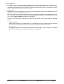
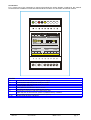
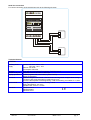
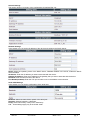
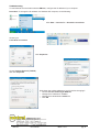
INSTRUCTION MANUAL
IM471-U v0.1
EMI-10L
Introduction
EMI-10L converter lets you convert a serial RS485 communications port on a bus Ethernet with TCP / IP.
The concepts and terms commonly used in the TCP / IP incorporated in this manual are:
Elements of an IP network
Any device, including routers and hosts, is running an implementation of IP address
Node
Node is not able to forward IP packets not explicitly addressed to itself, or a device does
Host
not like routers. An host is usually the source and destination of IP traffic
One or more LAN segments enclosed between the router and using the same IP
Subnet
address prefix
Two or more subnets connected by routers
Network
Representation of a physical or logical connection of a node to a subnet. A network card
Interface
is an example of a physical interface
Identifier that can be used as a source or destination of IP packets and is assigned at the
Address
level of the Internet interface or a set of interfaces
Tool offered by the operating system to applications to use the capabilities of the network
Socket
Transmission Control Protocol (TCP)
•
TCP is a connection-oriented protocol, it can transmit data to establish communication, negotiating a
connection between sender and recipient, and finally concludes with the closing of the connection. It
therefore has the capability to create, maintain and close a connection.
•
TCP guarantees that data transmitted, if they reach their destination, they do so in order and only once:
the protocol into practice trying to simulate a direct physical connection of a stream of bytes through
various mechanisms, acknowledgment and retransmission on timeout.
•
TCP has flow control capability and control congestion on the connection, through the mechanism of the
sliding window. TCP provides a service multiplexing of connections on a host, through the mechanism of
the doors.
•
Each connection is associated with an active TCP socket opened by a process. TCP is responsible for
changing data between the active connections and related processes. For this, each connection
between two hosts is associated with a port number on each of the two hosts, which is an unsigned 16bit (1-65535), contained in the appropriate field header.
•
A TCP connection will be identified by IP addresses of two hosts and ports used on the two hosts.
EMI-10L
user manual
IM471-U v0.1
pag. 1
Features EMI-10L
a) The EMI-10L This is a bridge between MODBUS/TCPIP and Modbus/ASCII/RTU. The serial port is
connected to a Modbus/ASCII or MODBUS/RTU device or a network of devices, while the Ethernet port is
connected to the server/PC or PLC systems. Commands are sent from the server via Ethernet, and the
slave device gets these after they've been converted.
b) Serial-Over-IP:
RS232 ports may have disappeared from your PC but serial interfaces continue to be widespread in many
industries such as security, automation and IT.
EMI-10L's serial-over-IP solutions marry the simplicity of serial communications with TCP/IP networking of
the Internet age. We supply external device, embedded Ethernet modules, and PC software that allow
you to quickly network-enable practically any serial device.
There are three basic ways to use EMI-10L's Serial-over-IP devices. Each of the methods is described
below:
1. Virtual Serial Ports
Virtual Serial Port Driver for Windows allow you to transparently access your device server's serial port
as if it was a real COM port of your PC. Your "serial" PC software won't notice the cheat.
2. Direct TCP link
The EMI-10L serial-over-IP devices support standard TCP/IP protocol. Open a socket and exchange
data with the serial port of your device server directly. It's that simple.
EMI-10L
user manual
IM471-U v0.1
pag. 2
Connections
For a correct use of the instrument to respect scrupulously the wiring diagram contained in this manual.
Connections are available on screw terminals and RJ45 connector for connection to Ethernet network.
link set data
service
ON
ethernet
ETHERNET MULTIFUNCTION INTERFACE
2x RS485 serial port
power supply
Vaux
Aux1
LEGEND
1,3
5,6
8,9
7
10
12
13
14
15-18
Aux2
serial ports RS485
COM1
COM2
A1 B1 gnd A2 B2
terminals for connecting the auxiliary power supply
communication with the RS485 serial port COM1
communication with the RS485 serial port COM2
ground RS485 serial port
Green LED for ON indication device access
Red LED indication receiving valid packet (LINK)
Push-button under the cover of the instrument (set):
(within the first 10 seconds from power on) Restore factory condition
Yellow LED indication for data transmission (DATA)
Module RJ45 ethernet 100 base-T
EMI-10L
user manual
IM471-U v0.1
pag. 3
Serial line connection
For correct connection of the serials lines refer to the following schemes:
ON
link set data
service
ethernet
ETHERNET MULTIFUNCTION INTERFACE
2x RS485 serial port
power supply
Vaux
Aux1
Aux2
serial ports RS485
COM1
COM2
A1 B1 gnd A 2 B2
Instrument’s network
B
A
G nd
Instrument’s network
G nd
B
A
Technical features
GENERAL
auxiliary power
supply
ethernet
RS485 serial port
display, operators
mechanic
enviromental
standards
EMI-10L
Version: Vac 220 - 240 +- 15%
Vac 100 - 130 +- 15%
Version: 24V ac/dc
consumption max 4VA
RJ45 jack and 10/100BaseT magnetics, TCP/IP protocol
standard, baudrate da 4800 a 19200 bps
3 LEDs (1 green: ON, 1 red: LINK, 1 yellow: DATA)
button programming
protection degree: IP52 frontal - IP20 enclosure and terminals - weight: about 0,4 kg
connection with screw terminals for cable max 2,5 mm 2
enclosure thermoplastic self-extinguishing – DIN rail mounting, 3 modules of 17,5mm
working temperature: -10÷60°C; humidity <90%
storing temperature: -25÷70°C
insulation test: 3 kV for 1 minute
CEI EN 50081-2
CEI EN 50082-1
CEI EN 61010-1
user manual
IM471-U v0.1
pag. 4
Configuration
This manual applies to firmware version "Current Version: EMI-10L-1_00” updates firmware may change
the structure of the configuration menu and the name of some fields, indicating the procedure be followed to
configure the device remains unchanged. In case of substantial upgrade contacted by email
[email protected] to request updated information, always putting in your e-mail the firmware version you're
using.
DEFAULT SETTINGS
IP address
10.0.0.100
Subnetmask
255.0.0.0
Gateway
10.0.0.254
TCP port
502
DHCP Server
Disabled
Username
contrel
Password
contrel
Common tasks
In any configuration window is the Save button that has the function to save the modified parameters in the
configuration of device.
Always press this button otherwise the changes will be lost.
The device has a default IP-address, if the device must be plugged into an existing network, configure at first
the IP address from the menu section NETWORK SETTINGS.
Configuration access
To access the configuration you must change the IP address of the PC. Follow the instructions at the bottom
of the following manual Troubleshooting section.
Open your browser (Internet Explorer, Firefox, Mozilla, Opera, etc. ..) and go at http://10.0.0.100
Please enter the correct Username and Password for administrator access and press Login button. It’s
possible to modify the Username and Password in the configuration of the device.
The menu, to access all the configuration pages, is available on the left side of the interface and has the
following structure:
General Settings:
Network Settings:
Page summary of the status of the device.
Local Area Network Settings, IP address, DHCP server, gateway address,
Subnetmask, TCP port number.
Serial COM Settings: Settings RS485 baudrate, databits, parity.
Modbus Settings:
Settings Modbus, Modbus protocol used for communication.
Administration:
General settings device (Device Name, Username, Password)..
Restore Default:
Reboot:
Log out:
EMI-10L
Restart the device with the factory settings.
Restart the device with the current configuration.
To exit properly at the end of each session.
user manual
IM471-U v0.1
pag. 5
General Settings
This section shows a summary of the configuration of interface EMI-10L.
Network Settings
In this section you can set the IP address of the device and configure the DHCP Server.
DHCP: Select the operating mode of the DHCP Server, Disabled disables in the server, enable the DHCP
Server Enabled.
IP-address: Enter the IP address you want to associate with the device.
Gateway IP-address: Enter the IP address of the gateway that you want to associate with the device.
Netmask: Enter the subnet mask of the device.
Port Number(0-65534): Enter the TCP port number to use in the Modbus communication.
Serial COM Settings
In this section you can set the configuration of the serial port.
Baudrate: Select the transmission speed of the serial port.
Data bits: Select 8 Data bits / 7 Data bits.
Parity: Select None Parity / Parity Even / Odd Parity.
N.B. : These settings apply only to the COM1 serial.
EMI-10L
user manual
IM471-U v0.1
pag. 6
Modbus Settings
In this section you can set the protocol used for communication Modbus.
Modbus Protocol: Select the communication protocol used. Modbus TCP-IP or Modbus RTU (Serial-OverIP).
Administration
In this section you can change some settings in general device.
Company Name: Enter the name of the company you want to assign to the device.
Device Name: Enter the name you want to assign to the mnemonic device.
Username: Enter the new name.
Password: Enter the new password.
It always advisable to change the password of the device as the default password is public domain.
.
EMI-10L
user manual
IM471-U v0.1
pag. 7
Troubleshooting
To use Ethernet communication with the EMI-10L, configure the IP address of your computer.
Procedure: To change the IP address of a Windows XP computer, do the following:
Click Start > Connect To > Show All Connections
Choose your
Local Area Connection
Click Properties
Choose Internet Protocol (TCP/IP)
and click Properties
Write down the existing address of your PC before changing it:
• Choose Use the Following IP Address
• Change the IP Address to 10.0.0.2
• Change the Subnet Mask to 255.0.0.0
• Click OK
EMI-10L
user manual
IM471-U v0.1
pag. 8