1
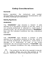
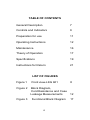
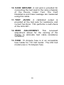
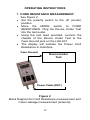
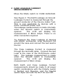
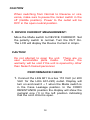
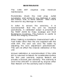
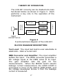
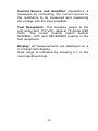
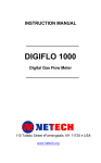
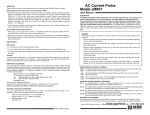
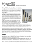
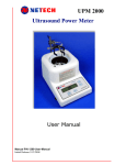
INSTRUCTION MANUAL
LKG 601
Electrical Safety Analyzer
110 Toledo Street • Farmingdale, NY 11735 • USA
http://www.Netech.org
510-USER-Manual Rev3
10/29/2007
Dear User,
We appreciate your purchase of the LKG 601
Electrical Safety Analyzer. Properly used, the LKG
601 will deliver years of high performance and
accuracy.
This instruction manual has been designed as a tool
to assist you in getting the most from your LKG 601.
In order to properly use and to maintain this
instrument, please read the manual carefully.
Netech is recognized as an innovative designer and
manufacturer of advanced biomedical and industrial
test instruments. We are ISO 9001-2000 Certified
and fully committed to a continuous improvement
process. Further, we guarantee absolute satisfaction
with our products.
Your business is important to us and we are
dedicated to providing you with the best customer
and technical service possible. Please contact us
should you have any questions or concerns regarding
your instrument.
We hope you will consider us again when you have a
requirement for accurate, reliable, affordable test
instruments.
Sincerely,
NETECH CORPORATION
Innovative Biomedical Test Instruments
2
Copyright
Copyright © 2002 by Netech Corporation. All rights
reserved. No part of this publication may be reproduced
or transmitted in any form other than for the purchaser’s
personal use without written permission from Netech
Corporation.
Quality Assurance
Netech Corporation is ISO 9001-2000 Certified. This
instrument was thoroughly tested and inspected
according to Netech’s ISO 9001-2000 quality standards
and test procedures, and was found to meet those
specifications when it was shipped from the factory.
Warranty
Netech warranties the LKG 601 against defects in
materials and workmanship for one year from the date
of original purchase. The standard warranty is
extended for a second year if the instrument is
returned to Netech for its recommended yearly
recalibration.
During the warranty period, we will repair or, at our
option, replace at no charge a product that proves to be
defective, provided you return the product shipping
prepaid to Netech Corporation. This warranty does not
apply if the product has been damaged by accident or
misuse, or as the result of service or modification by
other than Netech Corporation, or if its serial number is
defaced or removed.
3
Netech reserves the right to discontinue the LKG 601 at
any time, and change its specifications, price, or design
without notice and without incurring any obligation.
Netech guarantees availability of service parts for 5
years after the manufacture of the unit is discontinued.
The warranty is void if you elect to have the unit
serviced and / or calibrated by someone other than
Netech.
The purchaser assumes all liability for any damages or
bodily injury that may result from the use or misuse of
the unit by the purchaser, his employees, agents or
customers.
In no event shall Netech Corporation be liable for
consequential damages
Trademarks
Netech and LKG 601 are trademarks of Netech
Corporation. Any other trademark names used in this
manual are only for editorial purposes and the benefit of
the respective trademark owner, with no intention of
improperly using that trademark.
4
Safety Considerations
General
Before operation, the instrument and related
documentation must be reviewed for familiarization with
all safety markings and instructions
Safety Symbols
WARNING
The “WARNING” sign denotes a hazard. It calls
attention to a procedure, practice or the like, which, if
not correctly performed or adhered to, could result in
personal injury. Do not proceed beyond a “WARNING”
sign until the indicated conditions are fully understood
and met.
CAUTION
The “CAUTION” sign denotes a hazard. It calls
attention to a procedure, practice or the like, which, if
not correctly performed or adhered to, could result in
damage to or destruction of part or the entire
instrument. Do not proceed beyond a “CAUTION” sign
until the indicated conditions are fully understood and
met.
The symbol to the left is the operator’s manual
symbol. When you see this symbol on the
instrument, refer to the operator’s manual.
5
TABLE OF CONTENTS
General Description
7
Controls and Indicators
9
Preparation for use
11
Operating Instructions
12
Maintenance
16
Theory of Operation
17
Specifications
19
Instructions for Return
21
LIST OF FIGURES
Figure 1
Front view-LKG 601
8
Figure 2
Block Diagram,
Cord Resistance and Case
Leakage Measurements
12
Functional Block Diagram
17
Figure 3
6
GENERAL DESCRIPTION
The LKG 601 is a compact, low cost Electrical
Safety Analyzer designed to evaluate the basic
electrical safety of all electrical systems including
medical
devices
and
physiological
instrumentation.
The LKG 601 measures Electrical Leakage
Current, Power Cord Ground Resistance, and
Device Current.
The LKG 601 is simple to operate. A threeposition switch selects the test to be performed.
The user may select either the AAMI ESI-1993
or the IEC 601-1 test load to compensate for
high
frequency
components
in
the
measurement.
Accurate resistance measurements are made via
a simple method using a single conductor cable.
No special cables are required. A calibrated
output is provided through a test jack to verify the
performance of the LKG 601.
Key Features
• Compact.
• Easy to Use.
• Measures:
Device Current
Cord (Ground) Resistance
Ground Leakage Current
Case (Chassis) Leakage Current
• Test Jack for Calibrated Outputs.
• True RMS Measurement.
• AAMI or IEC 601 Test Load Selector.
7
11
10
1
13
12
7
2
4
3
5
6
8
9
Power Cable
Test Receptacle
Figure 1
Front view of the LKG 601
8
CONTROLS AND INDICATORS
1. DISPLAY: A 3½ Digit LCD indicates the result
of the measurement being made.
2. LEDS: 3 red LEDS indicate the selected test
mode.
3. MODE SWITCH: Three-position slide switch
to select the test measurement. A lit red LED
indicates the selection.
4. GROUND SWITCH: A switch to momentarily
open the ground connection to the test
receptacle.
5. POLARITY SWITCH: A three-position switch
to select the normal and reverse polarity of the
test receptacle. The center position shuts the
power off to the test receptacle.
6. NEUTRAL SWITCH: A switch to momentarily
open the neutral line to the test receptacle.
7. LOAD SELECTOR SWITCH: A slide switch
on the right side of the instrument to select
either the AAMI or the IEC 601-1 test load.
8. TEST RECEPTACLE: A 20 AMP power
receptacle for the Device Under Test.
9. POWER CORD: The power cord supplies
power to the analyzer and to the Device Under
Test.
9
10. CASE GROUND: A red jack is provided for
connecting the test lead to the case (chassis)
of the Device Under Test. The Cord
Resistance and Case Leakage are measured
using this cable.
11. TEST JACKS: A calibrated output is
provided at the test jack for resistance and
current functions. This performs a self-check
of the LKG 601.
12. ZERO ADJUSTMENT: This recessed
adjustment allows for the zeroing of the
display to eliminate test cable resistance
variations.
13. FUSE: 15 Ampere fuse is in an accessible
fuse holder for 110 Volt model. The 230 Volt
model uses a 10-Ampere fuse.
10
PREPARATION FOR USE
The LKG 601 includes a test lead for measuring
Cord Resistance and Case Leakage. No other
cables are required to perform measurements.
Connect the LKG 601 to a 110 VAC outlet (Or
220 VAC for 220-Volt Units).
Before proceeding with any measurement
become familiar with the measurements and the
function selector switch.
During the initial setup the last digit of the LCD
will change gradually due to the time constant of
the RMS to DC converter. The display will
stabilize to zero in a few seconds.
CAUTION
Make sure that the power requirements of the
Device Under Test are within the power ratings
of the LKG 601, 15 amps at 110 volts and 10
amps at 230 volts.
CAUTION
Do not leave the Device Under Test
continuously turned on and connected to the
LKG601.
11
OPERATING INSTRUCTIONS
1. CORD RESISTANCE MEASUREMENT:
•
•
•
•
See Figure 2.
Set the polarity switch to the off (center)
position.
Move the MODE switch to CORD
RESISTANCE. Plug the Device Under Test
into the test outlet.
Using the test lead provided, connect the
chassis of the Device Under Test to the
Case Ground jack on the LKG 601.
The display will indicate the Power Cord
Resistance in milliohms.
Case Ground
Device Under
Test
Power Cable (DUT)
Figure 2
Block Diagram for Cord Resistance measurement and
Case Leakage measurement (external).
12
2. CASE LEAKAGE CURRENT
MEASUREMENTS:
Move the Mode switch to CASE LEAKAGE.
See Figure 2. The Earth Leakage (or Ground
Leakage) Current is measured through the
ground conductor of the Device Under Test.
This is only applicable to devices with a
three- conductor power cord.
The leakage measurement is made internally
when the Ground switch is momentarily
opened.
The LCD will display the
measurement in Micro Amps. There is no
other connection required.
To measure the Case Leakage of devices
with plastic enclosures, wrap aluminum foil
around the case and connect the test lead to
the foil.
The Case Leakage Current is measured
through the test lead cable. Connect the test
Lead to the case of the DUT(Device under
test). The leakage measurement is made
when the Ground switch is momentarily
opened.
The LCD will display the
measurement in Micro Amps.
Both Earth and Case Leakage Current
measurements should be made in all power
switch combinations with the Polarity switch
in Normal and Reverse, and the Neutral
switch Open and with the DUT On and Off.
13
CAUTION
When switching from Normal to Reverse or vice
versa, make sure to pause the rocker switch in the
off (middle position). Power to the outlet will be
OFF in the open neutral position.
3. DEVICE CURRENT MEASUREMENT:
Move the Mode switch to DEVICE CURRENT. Set
the polarity switch to normal. Turn the DUT On.
The LCD will display the Device Current in Amps.
CAUTION
Do not attempt to open the unit. There are no
user serviceable parts inside.
Further, the
warranty will be void if the unit is opened by other
than Netech trained personnel.
PERFORMANCE CHECK
1. Connect the LKG 601 to a live 110 VAC (or 220
VAC for the LKG 601-220) outlet. Display will
turn on and read 0 ± 1 when the Mode switch is
in the Case Leakage position. In the CORD
RESISTANCE position the display will show the
numeral one (1) in the left position indicating
that the cord circuit is open.
14
2. Move the Mode selector switch to all three
positions and test the LED indication.
3. Check the continuity between receptacle
ground and case ground using the test cable.
If necessary adjust the display to zero. When
the open ground switch is pressed down the
connection will be open.
4. Connect the Test Lead to the TEST JACK.
Move the selector switch to CORD
RESISTANCE. The reading should be 1010
milliohms + 5%.
5. Move the switch to CASE LEAKAGE. The
display will indicate 200 Micro Amps + 2%.
These tests will confirm that the LKG 601 is
working properly.
15
MAINTENANCE
The LKG 601
maintenance.
requires
only
minimum
Periodically check the inlet plug, outlet
receptacle, and wiring for any damage or wear
like cracks, cuts, or other defects. Also check
the case for any damage or cracks.
In order to ensure the accuracy, it is
recommended that the unit be checked
periodically. A calibrated output is provided at
the TEST JACK for Case Leakage and Cord
Resistance functions. This feature is useful to
check the integrity of the unit.
When making a resistance measurement with a
Test Cable other than the one supplied with the
LKG 601, the user can zero the leads by
adjusting the zero adjustment potentiometer.
This will not affect the internal calibration of the
unit.
Annual calibration is recommended. If the LKG
601 is returned to Netech for recalibration before
the first year warranty expires Netech will
provide a second year warranty. The warranty is
void if the LKG 601 is serviced by anyone other
than Netech or if the warranty seal is broken.
16
THEORY OF OPERATION
The LKG 601 circuitry can be divided into main
functional blocks as shown in Figure 3. Each
performs a key role in the operation of the
instrument.
AAMI or
IEC 601
RMS TO
DC
CURRENT
SOURCE
DISPLAY
FUNCTION
SELECTOR
LEDS
AMP
TEST
RECEPTACLE
Figure 3
Functional block diagram of the LKG 601.
BLOCK DIAGRAM DESCRIPTION
Test Load: The input test load is user selectable to
AAMI ESI –1993 or to IEC 601.
RMS Converter and Amplifier: The input amplifier
buffers the input. The RMS converter generates a
DC voltage equal to the RMS value at its input.
The gain Amplifier sets the gain for the
measurements. When the MODE switch selects
leakage current measurement, the AAMI LOAD is
connected in front of the INPUT AMPLIFIER, and
the voltage developed across it from the leakage
current is measured.
17
Current Source and Amplifier: Resistance is
measured by connecting the current source to
the resistance to be measured and measuring
the voltage with the input amplifier.
Test Receptacle: This supplies power to the
unit under test, 110 VAC rated at 15 Amps (220
VAC). The rocker polarity switch selects
NORMAL, OFF and REVERSES polarity in the
test receptacle.
Display: All measurements are displayed on a
3-1/2 digit LED display.
Over range is indicated by showing a 1 in the
most significant digit.
18
SPECIFICATION
S METER: 3-1/2 Digit LED
display.
LEAKAGE CURRENT: 0-1999 Micro Amps.
All Current measurements are made through
the AAMI/ANSI ES1-1985 or IEC 601-1 test
load. The meter readings correspond to the
true RMS value of the current.
Accuracy:
± 1% of reading, + 1
LSD DC to 1 KHz,
± 2.5% of reading + 1 LSD
1 Khz to 100 KHz,
± 5% of reading + 1 LSD
100 KHz to 1 MHz,
RESISTANCE: 0 TO 1999 Milli Ohms.
Accuracy: + 1 % of reading + 1 LSD
DEVICE CURRENT: 0 to 19.99 Amps
Accuracy: + 2% Full Scale + 1 LSD
TEST RECEPTACLE: Hospital Grade 110 VAC
-15 Amp or 220 VAC 10 Amp.
The rocker polarity switch selects NORMAL,
OFF and REVERSE Polarity to the test
receptacle, and a momentary Neutral switch will
open the neutral line to the test receptacle.
POWER REQUIREMENTS: 110 VAC 50-60Hz,
15 Amps or 220 VAC, 10 Amps maximum rated
for the test outlet and 0.1 Amp rated for the unit.
19
PHYSICAL DIMENSIONS:
Size: 5.5x 3.25 x 2.5 Inches
Weight: 1 lbs (.45kg)
ENVIRONMENTAL:
Operating range: 59 to 950 F (15 to 400 C)
Storage Temperature: 0 to 1220 F (-20 to 600 C)
Relative Humidity: 90% (max) at temperatures
STANDARD ACCESSORIES:
Description
User Manual
Test Cable
Part Number
510-MANUAL
503
OPTIONAL ACCESSORIES:
Description
Soft Carrying Case
Part Number
510-Case
20
INSTRUCTIONS FOR RETURN
Damaged in Transit:
All shipments are carefully examined by
NETECH and carefully packaged for shipment.
They are insured in the customer’s name with
the carrier. On receipt, if the shipping container
appears to have been damaged during
shipment, the instrument should be thoroughly
inspected.
The delivering carrier’s paper should be signed
noting the apparent damage. If the instrument is
damaged beyond use, a new order should be
placed
with
NETECH
while
awaiting
reimbursement from the carrier for the damaged
instruments.
Malfunction:
Please follow these steps for the repair or
recalibration of your NETECH instrument:
1. Obtain a Service /Repair Form
from our website at
www.Netech.org
Or from
Customer Service Department
Phone: 631-531-0100.
Fax: 631-531-0101
Toll Free: 800-547-6557
21
2. Complete the Service Form indicating the
instrument’s model number, serial number,
shipping, and billing information. Include the
purchase order number or credit card information
for the cost of the repair and/or recalibration.
3. Securely package your instrument in a strong
box, surrounded by at least two inches of suitable
shock absorbing material.
4. Include a copy of the purchase order, or
reference your purchase order on your packing
slip.
5. Include the completed Service Form.
6. Ship the instrument to the following address:
NETECH CORPORATION
110 Toledo Street
Farmingdale, NY 11735
ATTN: SERVICE DEPT.
For the latest Revisions and updates visit
www.netech.org
22