1
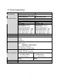
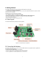
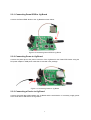
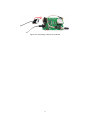
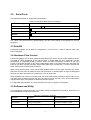
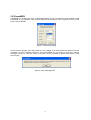
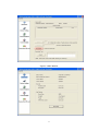
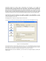
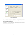
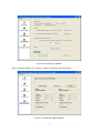
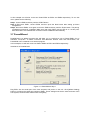
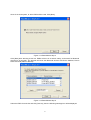
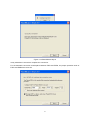
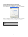
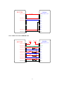
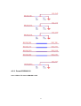
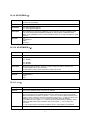
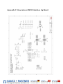
HANTZ + PARTNER The Upgrade Company! www.hantz.com Parani-ESD100/110/200/210 User Guide Version 1.0.2 2006-08-17 HANTZ + PARTNER The Upgrade Company! www.hantz.com Deutschland: Tel.: 0761 / 59 21 00 Fax: 0761 / 58 52 28 Schweiz: Tel.: 061 / 27 311 - 31 Fax: 061 / 27 311 - 39 Österreich: Tel.: 01 / 58 55 430 Fax: 01 / 58 55 460 User Guide for the Parani-ESD100/110/200/210 Version 1.0.2 Firmware version 1.0.X Last revised on Aug 17, 2006 Printed in Korea Copyright Copyright 2006, Sena Technologies, Inc. All rights reserved. Sena Technologies reserves the right to make changes and improvements to its product without providing notice. Trademark Parani™ is a trademark of Sena Technologies, Inc. Windows® is a registered trademark of Microsoft Corporation. Ethernet® is a registered trademark of XEROX Corporation. Notice to Users When a system failure may cause serious consequences, protecting life and property against such consequences with a backup system or safety device is essential. The user agrees that protection against consequences resulting from system failure is the user's responsibility. This device is not approved for life-support or medical systems. Changes or modifications to this device not explicitly approved by Sena Technologies will void the user's authority to operate this device. Precautions and Safety Electricity Use only the supplied AC adapter. Use of unauthorized power adapter is not recommended. Electrical shock may result. Do not kink or crease the power cable or place heavy objects on the power cable. Fire can result from damaged power cables. Do not handle power plug and adapter with wet hands. Electrical shock may result. Immediately power off the product and unplug the AC adapter if smoke or odors emit from the product and adapter. Fire can result from improper use. Immediately power off the product and unplug the AC adapter if water or other liquids are present. Fire can result from improper use. Product Parani-ESD meets the RS-232 standards. Do not wire with non-standard products. Damage to your products may result from improper use. Do not drop or subject the device to impact. Damage to your products may result from improper use. Keep away from harsh environments including humid, dusty, and smoky areas. Damage to your products may result from improper use. Do not use excessive force on the buttons or attempt to disassemble the device. Damage to your products may result from improper use. Do not place heavy objects on the product. Damage to your products may result from improper use. 2 Contents 1. Introduction… … … … … … … … … … … … … … … … … … … … … … … … … … … … … … .6 1.1. Overview… … ........................................................................................................................6 1.2. Package Check List ..............................................................................................................6 1.2.1. Single/Bulk Unit Package ............................................................................................ 6 1.2.2. Starter’s Kit.................................................................................................................. 6 1.3. Product Specification............................................................................................................. 7 2. Getting Started… … … … … … … … … … … … … … … … … … … … … … … … … … … … … 8 2.1. Panel Layout......................................................................................................................... 8 2.2. Connecting the Hardware......................................................................................................8 2.2.1. Connecting Parani-ESD to Jig Board........................................................................... 9 2.2.2. Connecting Power to Jig Board.................................................................................... 9 2.2.3. Connecting a Device to Jig Board ................................................................................9 3. Configuration… … … … … … … … … … … … … … … … … … … … … … … … … … … … … 11 3.1. Operation Modes................................................................................................................. 11 3.2. Serial Ports ......................................................................................................................... 12 3.3 Data Bit… … … … .................................................................................................................. 12 3.4 Hardware Flow Control......................................................................................................... 12 3.5 Software and Utility .............................................................................................................. 12 3.6 ParaniWIN ........................................................................................................................... 13 3.7 ParaniWizard ....................................................................................................................... 19 3.8 ParaniUpdater...................................................................................................................... 24 3.9 Terminal Program................................................................................................................. 24 4. Approval Information… … … … … … … … … … … … … … … … … … … … … … … … … .. 26 4.1. FCC… … … .......................................................................................................................... 26 4.1.1. FCC Compliance Statement ...................................................................................... 26 4.1.2. RF Exposure Statement ............................................................................................ 26 4.1.3. Do not ....................................................................................................................... 26 4.2. CE… … … ............................................................................................................................ 26 4.2.1. EC-R&TTE Directive.................................................................................................. 26 5. RF Information… … … … … … … … … … … … … … … … … … … … … … … … … … … … ..27 5.1. Radio Frequency Range...................................................................................................... 27 5.2. Number of Frequency Channel............................................................................................ 27 5.3. Transmission Method .......................................................................................................... 27 5.4. Modulation Method.............................................................................................................. 27 5.5. Radio Output Power............................................................................................................ 27 5.6. Receiving Sensitivity ........................................................................................................... 27 5.7. Power Supply...................................................................................................................... 28 Appendix A: Connections… … … … … … … … … … … … … … … … … … … … … … … … .. 29 A.1. Pin Assignment................................................................................................................... 29 A.1.1. Parani-ESD100/110 .................................................................................................. 29 A.1.2. Parani-ESD200/210 .................................................................................................. 30 A.1.3. DCD Signal............................................................................................................... 30 A.1.4. RST Signal................................................................................................................ 31 A.1.5. Pairing Signal (only for Parani-ESD100/110)............................................................. 31 A.2. Connection Diagram ........................................................................................................... 32 A.2.1. Parani-ESD100/110 .................................................................................................. 32 A.2.2. Parani-ESD200/210 .................................................................................................. 34 Appendix B: AT Commands… … … … … … … … … … … … … … … … … … … … … … … .. 37 B.1. Terminology ........................................................................................................................ 37 B.1.1. AT Command ............................................................................................................ 37 B.1.1. AT Response............................................................................................................. 37 B.1.2. Operation Mode ........................................................................................................ 37 B.1.3. Operation Status ....................................................................................................... 37 B.1.4. Security .................................................................................................................... 37 3 B.1.5. Symbols .................................................................................................................... 38 B.2. Command Category............................................................................................................ 38 B.3. Command Description ........................................................................................................ 39 B.3.1. ATZ......................................................................................................................... 39 B.3.2. AT&F....................................................................................................................... 39 B.3.3. AT........................................................................................................................... 39 B.3.4. AT+UARTCONFIG,Baudrate,Parity,Stopbit,Hwfc...................................................... 39 B.3.5. AT+BTINFO?.......................................................................................................... 40 B.3.6. AT+BTINQ?............................................................................................................. 40 B.3.7. AT+BTLAST?.......................................................................................................... 40 B.3.8. AT+BTVER?............................................................................................................ 40 B.3.9. AT+BTRSSI,n.......................................................................................................... 41 B.3.10. AT+BTMODE,n..................................................................................................... 41 B.3.11. +++....................................................................................................................... 41 B.3.12. AT+SETESC,nn.................................................................................................... 42 B.3.13. ATO....................................................................................................................... 42 B.3.14. AT+BTCANCEL..................................................................................................... 42 B.3.15. AT+BTSCAN......................................................................................................... 42 B.3.16. AT+BTSCAN,n,to.................................................................................................. 42 B.3.17. AT+BTSCAN112233445566,to.............................................................................. 43 B.3.18. ATD....................................................................................................................... 43 B.3.19. ATD112233445566................................................................................................ 44 B.3.20. ATH....................................................................................................................... 44 B.3.21. AT+BTKEY=$string............................................................................................... 44 B.3.22. AT+BTSD? ........................................................................................................... 44 B.3.23. AT+BTCSD........................................................................................................... 45 B.3.24. AT+BTFP,n............................................................................................................ 45 B.3.25. AT+BTSEC,Authentication,Encryption................................................................... 45 B.3.26. AT+BTNAME=$string............................................................................................ 45 B.3.27. AT+BTLPM,n......................................................................................................... 46 B.3.28. AT+DFU................................................................................................................ 46 B.3.29. AT&V..................................................................................................................... 46 B.3.30. ATSnn? ................................................................................................................ 46 B.3.31. ATSnn=mm........................................................................................................... 46 B.4. Command Validity............................................................................................................... 47 Appendix C: S-Register… … … … … … … … … … … … … … … … … … … … … … … … … .. 49 C.1. S1: Force to Reconnect (default 1) ..................................................................................... 49 C.2. S3: Stream UART Policy (default 0) .................................................................................... 49 C.3. S4: Enable Remote Name Query (default 1) ....................................................................... 49 C.4. S6: Enable Low Power Mode (default 0)............................................................................. 49 C.5. S10: Enable SD Response (default 1)................................................................................. 50 C.6. S11: Enable Escape (default 1)........................................................................................... 50 C.7. S12: Clear Data Buffer When Disconnected (default 0) ....................................................... 50 C.8. S14: Enable DTR Transfer (default 1) ................................................................................. 50 C.9. S15: Enable Disconnect by DTR (default 0) ........................................................................ 50 C.10. S22: Fast Connect (default 0) ........................................................................................... 50 C.11. S24: Maximum Number of Inquiry Result (default 10)........................................................ 50 C.12. S28: Escape Sequence Character (default 43).................................................................. 51 C.13. S31: Page Timeout (default 300)....................................................................................... 51 C.14. S33: Inquiry Timeout (default 30) ...................................................................................... 51 C.15. S37: Supervision Timeout (default 16000)......................................................................... 51 C.16. S46: BD Address of Last Connected Device ..................................................................... 51 Appendix D: Trouble Shooting… … … … … … … … … … … … … … … … … … … … … … . 52 D.1 No Data Transmission ......................................................................................................... 52 D.1.1 COM Port Settings..................................................................................................... 52 D.2 Data Loss or Malfunctioning................................................................................................. 52 4 D.2.1Hardware Flow Control ............................................................................................... 52 D.2.2 SD Response ............................................................................................................ 52 D.3 Transmission Delay ............................................................................................................. 52 D.3.1 RF Processing Delay ................................................................................................. 52 D.3.2 RF Transmission Environment ................................................................................... 53 Appendix E: Warranty… … … … … … … … … … … … … … … … … … … … … … … … … … . 54 E.1. GENERAL WARRANTY POLICY ........................................................................................ 54 E.2. LIMITATION OF LIABILITY ................................................................................................. 54 E.3. HARDWARE PRODUCT WARRANTY DETAILS................................................................. 54 E.4. SOFTWARE PRODUCT WARRANTY DETAILS ................................................................. 55 E.5. THIRD-PARTY SOFTWARE PRODUCT WARRANTY DETAILS ......................................... 55 Appendix F: How make a RS232 interface Jig Board… … … … … … … … … … … … .56 5 1. Introduction 1.1. Overview Parani-ESD is a module device for wireless serial communication using Bluetooth technology that is international a standard for short range wireless communications. Parani-ESD can communicate with other Bluetooth devices that support the Serial Port Profile. Parani-ESD lineup has several models with different communication ranges from 30m (ParaniESD200/210) up to 100m (Parani-ESD100/110) for use with various applications. The Parani-ESD delivers better quality of communication than a standard RS232 cables. Parani-ESD has a compact design and can be placed conveniently into devices or equipment. Its detachable antenna optimizes the quality and distance for wireless communications. Parani-ESD supports FHSS (Frequency Hopping Spread Spectrum), which is a technique, native to Bluetooth that allows the Parani-ESD minimize radio interference while decreasing the likelihood of over-air hijacking. Parani-ESD also supports authentication and Bluetooth data encryption. Parani-ESD can be configured and controlled by typical AT commands. Users can easily configure Parani-ESD by using a terminal program such as HyperTerminal and can use Bluetooth wireless communication without modifying user’s existing serial communication program. In addition to the basic AT commands, Parani-ESD provides some expanded AT commands for various functions. User friendly ParaniWizard and ParaniWIN are also provided for easy setup on Microsoft Windows. 1.2. Package Check List 1.2.1. Single/Bulk Unit Package Parani-ESD100/200 - Parani-ESD100/200 module - on-board chip antenna Parani-ESD110/210 - Parani-ESD110/210 module - Stub Antenna - Antenna extension cable 1.2.2. Starter’s Kit - Jig board - Serial data cable - DC Power Adapter - A hardcopy of Quick Start Guide - CD-ROM including the Configuration S/W and User Guide 6 1.3. Product Specification Serial Interface Bluetooth Interface Configuration Firmware Update Diagnostic LED Power Environmental Physical properties Approvals Warranty ESD100/110 ESD200/210 Serial speeds 1200bps to 230400bps Flow Control: None, Hardware RTS/CTS 2.54mm Header 2X6 2.54mm Header 1X4X2 Bluetooth v1.2 Protocol: RFCOMM, L2CAP, SDP Profile: Serial Port Profile Class 1 Class 2 Level: 18dBm Level: Max. 4dBm ESD100-Working distance: ESD200-Working distance: Nominal 100m Nominal 30m ESD110-Working distance: ESD210-Working distance: Default–Default Antenna 100m Default–Default Antenna 30m Default–Dipole Antenna 150m Default–Dipole Antenna 50m Dipole–Dipole Antenna 200m Dipole–Dipole Antenna 80m Patch–Dipole Antenna 400m Patch–Dipole Antenna 150m Patch–Patch Antenna 1000m Patch–Patch Antenna 300m ParaniWIN, ParaniWizard, Modem AT command set ParaniUpdater for SD&ESD Power Standby Connect Serial Rx/Tx Supply voltage: 3.3V DC Supply current: - ESD100/110 : minimum 300mA - ESD200/210 : minimum 150mA Nominal power consumption 26mA@9600pbs, 29mA@115Kbps Operating temperature: -10 ~ 55 oC Storage temperature: -20 ~ 70 oC Humidity : 90% (Non-condensing) Dimension Dimension 27.5 mm L (1.08 in.) 18 mm L (0.7 in.) 27.7 mm W (1.09 in.) 20 mm W (0.78 in.) 14 mm H (0.55 in.) 11.7 mm H (0.47 in.) Weight 5g FCC(A), CE(A), MIC 1-year limited warranty Weight 2g 7 2. Getting Started This chapter describes how to set up the Parani-ESD Series for the first time. - 2.1 Panel Layout explains the panel layout. - 2.2 Connecting the Hardware describes how to connect the Parani-ESD Series, the power, and the serial device to the Jig Board. Following items are pre-required to get started. - One Jig Board (included in the Starter Kit package). - One DC power adapter or one USB power cable (included in the Starter Kit package). - One serial console cable for configuration (included in the Starter Kit package). - One PC with RS232 serial port. - Terminal emulation program running on the PC 2.1. Panel Layout This section describes the panel layout of the Jig Board. Figure 2-1 The panel layout of Jig Board 2.2. Connecting the Hardware This section describes how to connect the Parani-ESD Series to the Jig Board and the Jig Board to the serial device for initial testing. - Connect the Parani-ESD Series to the Jig Board. - Connect a power source to Jig Board for the Parani-ESD Series. - Connect Jig Board for the Parani-ESD Series to a serial device. 8 2.2.1. Connecting Parani-ESD to Jig Board Connect the Parani-ESD Series to the Jig Board as shown below. Figure 2-2 Connecting Parani -ESD to Jig Board 2.2.2. Connecting Power to Jig Board Connect the power jack to the power connector of the Jig Board for the Parani-ESD Series using the DC power adapter or USB power cable that is included in the package. Figure 2-3 Connecting Power to Jig Board 2.2.3. Connecting a Device to Jig Board Connect the serial data cable between the Jig Board and the serial device. If necessary, supply power to the serial device attached to the Jig Board. 9 Figure 2-4 Connecting a Device to Jig Board 10 3. Configuration 3.1. Operation Modes In addition to the serial port configurations, the Parani-ESD requires also includes some settings for Bluetooth. For getting the most out of Parani-ESD, user should understand the following Bluetooth connection schemes. A Bluetooth device can play a role as a master or slave. Master tries to connect itself to other Bluetooth devices, and slave is waiting to be connected from other Bluetooth devices. A Bluetooth connection is always made by a pair of master and slave devices. A slave can be in two modes, Inquiry Scan or Page Scan mode. Inquiry Scan mode is waiting for a packet of inquiry from other Bluetooth device and Page Scan mode is waiting for a packet of connection from other Bluetooth device. Every Bluetooth device has its unique address, called BD (Bluetooth Device) address, which is composed of 12 hexa-decimal numbers. Parani-ESD has 4 operation modes as follows: Table 3-1 The Parani-ESD Operation Modes Mode Description Mode0 In this mode, there is no response when power on or software reset, and Parani-ESD is just waiting for AT command input. Neither master nor slave is assigned to Parani-ESD in mode0. User can change the configuration parameters of Parani-ESD in this mode. Parani-ESD must be in Mode0, when it is directly controlled by AT commands. The factory default is set to Mode0. Mode1 Parani-ESD tries to connect the last connected Bluetooth device. Parani-ESD in Mode1 is to be a master and tries to connect the last connected Bluetooth device. Parani-ESD always stores the BD address of the Bluetooth device to which ParaniESD has connected last. When Parani-ESD is initially used or after hardware reset, there is no BD address stored in Parani-ESD. In this case, Mode1 will not be able to work properly. The mode change to Mode1 can be made after Parani-ESD succeeds to connect to one other Bluetooth device. Once changed to Mode1, Parani-ESD will try to connect automatically the last connected Bluetooth device whenever the unit is powered on or software reset. Parani-ESD in Mode1 cannot be discovered or connected by other Bluetooth devices. Mode2 Parani-ESD is waits for a connection from the last connected Bluetooth device. Parani-ESD in Mode2 is to be a slave and waiting for the connection only from the last connected Bluetooth device. Just like Mode1, if there is no BD address stored in Parani-ESD, the mode change from other operation modes to Mode2 is not work properly. Once changed to Mode2, Parani-ESD will wait for the connection from the last connected Bluetooth device whenever the unit is powered on or software reset. Parani-ESD in Mode2 cannot be discovered or connected to Bluetooth devices other than the last connected device. Mode3 Parani-ESD is waiting for the connection from any other Bluetooth devices. In Mode 3 the Promi-ESD is discoverable and can be connected to by other Bluetooth devices. 11 3.2. Serial Ports The applicable settings for serial ports are as follows. Table 3-2 The Parani-ESD Serial Port Settings Serial Port Settings Values Baud rate 1200, 2400, 4800, 9600, 19200, 38200, 57600, 115200, 230400 Data bite 8 Parity No parity, Even parity, Odd parity Stop bit 1, 2 Hardware Flow Control Use, No Use The values in box are the factory default settings. The flow control setting is configurable only through dip switch. 3.3 Data Bit Parani-ESD supports only 8 data bit configurations. In the case of 7 data bit, please contact the technical support. 3.4 Hardware Flow Control Parani-ESD plugged into its host system transmits data fro m host to the other side Bluetooth device. This data is saved temporarily in the internal buffer of Parani-ESD and sent repeatedly until the transmission is completed packet by packet. When the radio transmission condition is not good enough to send data promptly, it can cause a transmission delay. If the host sends more data when the buffer is full, buffer overflow will make Parani-ESD malfunction consequently. In order to prevent this buffer overflow, Parani-ESD works as follows. When using hardware flow control, Parani-ESD disables RTS so that it stops receiving any further data from the host when the buffer becomes full. RTS will be re-enabled again to begin receiving data from the host when the buffer has created more room for more data. When hardware flow control is not being used, the Parani-ESD clears the buffer to secure room for the next data when the buffer becomes full. This can mean a loss of data may occur. As the transmission data becomes large, the possibility of data loss becomes greater. For large data transmissions, the use of hardware flow control is highly recommended. 3.5 Software and Utility This configuration software and utility for firmware update is included with the product, which also can be downloaded from http://www.sena.com Table 3-3 Configuration Software Software Purpose Operating System ParaniWIN Configuration MS Windows 98SE or Higher ParaniWizard Pairing Configuration MS Windows 98SE or Higher ParaniUpdater Firmware Update MS Windows 98SE or Higher 12 3.6 ParaniWIN ParaniWIN is a program that runs on Microsoft Windows for the configuration of Parani-ESD. Install ParaniWIN on your computer. Plug a Parani-ESD into the serial port of the computer and turn on the power. Run ParaniWIN. Figure 3-1 Serial Port Setting Set each option properly and click [Confirm]. If the settings of the Parani-ESD are different from the ParaniWin, an error message will pop up. If the Parani-ESD is in the status of connection, warning message will pop up. Then the current connection can be cancelled by [Disconnect] button on the main window. Figure 3-2 Error Message Box 13 Figure 3-3 Main Window 14 Figure 3-4 Information Window Serial port settings can be changed by <Start Configuration> and <ParaniWIN Configuration> of ParaniWIN in the menu bar at upper left corner of the window without re-running the ParaniWIN program. Figure 3-5 Menu Bar at Upper Left corner of ParaniWIN When the ParaniWin software is able to access the Parani-ESD properly, the icons in the left side window come will become available for use. In device configuration window, hardware reset can be executed or operation mode and RS232 can be configured as well. Security option also can be configured in this window. Figure 3-6 Device Setting Window Parani-ESD supports two security options, Authentication and Encryption. If you check the Authentication option, you must also enter the Pin Code value. If the authentication is activated, the connection, only between the Master and Slave device that share the same Pin Code, is established. 15 Parani-ESD supports two security options, Authentication and Encryption. If you enable the Authentication option, you must also enter a Pin Code value. If the authentication is enabled, the connection, between the Master and Slave device must share the same Pin Code. In case that ParaniESD connects to another Bluetooth device, that requires authentication, you must know the other device’s Pin Code. In general, most Bluetooth devices have a pincode of 1234 or 0000. If you check Encryption option, the Parani-ESD will encrypt packets and sent to the device. The Encryption options works well in case that only one of the devices between Master and Slave use the Encryption option. Parani-ESD has 4 response messages, ‘OK’, ‘ERROR’, ‘CONNECT’, and ‘DISCONNECT’. In some cases, these responses can affect the host system unexpectedly. To prevent this, user can set the Command response to ON or OFF. Click [Apply] button to apply any changes made to the Promi-SD. Connect(out) icon will show the following window to search and connect other Bluetooth devices. Figure 3-7 Connect(out) Window Click [Search] button to search nearby Bluetooth devices. Once several Bluetooth devices has been found, select one of the devices and click the [Connect] button. The selected Bluetooth device must be discoverable and connectable. Click [Disconnect] button to cancel the connection. After the connection has been established, you will be able to test signal strength by pushing the START button. 16 Figure 3-8 Signal Strength Test The signal strength test shows LInkQuality and RSSI values. The closer LinkQuality is to 255 and RSSI is to 0, this means the Promi-ESD has a good connection to the connected Bluetooth device. In general, the wireless connectivity is at its best within 10 meters. You can push the STOP button at anytime in order to terminate the signal strength test. The signal strength test will continue until the STOP button is pushed. If you close the ParaniWIN Window without pushing the STOP button, you must restart Parani-ESD to terminate the test. Connection(in) icon will show the following window, which enables the Parani-ESD to wait for a connection from another Bluetooth device. If the waiting time is set to 0, Parani-ESD will continually wait for connection until [Cancel] button is clicked. 17 Figure 3-9 Connection(in) Window If the Connection Wizard icon is clicked, an easy to use pairing menu will appear: Figure 3-10 Connection Wizard Window 18 In this example we will refer to the two Parani-ESDs as ESD1 and ESD2 respectively. To use this menu, please do the following: Step 1. Connect ESD1 and then push the START button. Step 2. Disconnect ESD1, connect ESD2 and then push the Next button after setting up Slave configuration. Step 3. Disconnect ESD2, once again connect the ESD1 and then push the Finish button. The pairing configuration should be completed. Make sure that each ESD’s connect LED is on. At this point, when both ESD’s are restarted the connection will be established automatically. 3.7 ParaniWizard ParaniWizard is a Wizard program that will allow you to configure a pair of Parani-ESD’s for an automatic connection. To make connection with Bluetooth devices other than Parani -ESD, use ParaniWIN or AT commands on a terminal program. In this example, we will refer to the two Parani-ESD’s as ESD1 and ESD2 respectively. Install and run ParaniWizard. Figure 3-11 ParaniWizard Step 1 Plug ESD1 into the serial port of the host computer and power on the unit . Click [Wizard Setting] button to configure the serial port settings of ESD1. These settings must be the same as those of the host system, to which ESD1 will be used. Click [Next]. 19 Figure 3-12 ParaniWizard Step 2 Click [Next] with after selecting the check box, which makes the unit discoverable, in which ESD1 can be discovered and connected from the other Bluetooth device. Remove ESD1 from the host computer, remember to leave the ESD1 powered on. Now, plug ESD2 into the serial port of the host computer and power on the unit. Figure 3-13 ParaniWizard Step 3 Click [Wizard Setting] button to configure the serial settings of ESD2. These settings must be same as 20 those of the host system, to which ESD2 will be used. Click [Next]. Figure 3-14 ParaniWizard Step 4 Click [Next] after selecting check box. ESD2 will then do a search nearby, and search for Bluetooth devices for 30 seconds. The program will show the Bluetooth devices with Device Address, Device Name and CoD (Class of Device). Figure 3-15 ParaniWizard Step 5 Select the ESD1 from the list and click [Connect], then the following message box will be displayed. 21 Figure 3-16 ParaniWizard Step 6 It may take about 5 seconds to complete the connection. For the automatic connection to take place between ESD1 and ESD2, the proper operation mode of ESD1 and ESD2 have to be set. 22 Figure 3-17 ParaniWizard Step 7 Set the operation mode of ESD2 to Mode1. Figure 3-18 ParaniWizard Step 8 Remove the ESD2 from the host computer and plug ESD1 into the serial port again. Set the operation mode of ESD1 to Mode2. Figure 3-19 ParaniWizard Step 9 23 Now the configuration of ESD1 and ESD2 has been completed. Now when the units are turned off and then turned on again, they will make an automatic connection to each other. 3.8 ParaniUpdater Parani-ESD supports firmware updates. You can download new firmware images for the Parani-ESD at http://www.sena.com. With the ParaniUpdater, you can update the firmware of Parani-ESD by selecting the firmware image file and pushing Start button. * Note: DO NOT power off Parani-ESD while the firmware update is progressing, this may damage the Parani-ESD. Figure 3-20 ParaniUpdater Window . 3.9 Terminal Program A terminal program is typically an application that will enable a PC to communicate directly with a modem. If you are using Windows 98SE or higher version of Windows, HyperTerminal program is included as part of the operating system. Parani-ESD provides some extended AT commands for configuration of the Parani-ESD. This manual will explain the method using HyperTerminal. If you need to install HyperTerminal, click start>setting>control panel>add/remove programs. For more precise details on HyperTerminal installations, please refer to Microsoft Windows Help section. Attach Parani-ESD to serial port of host computer and power on the unit. Launch HyperTerminal. It can be found in start menu >programs >accessories >communication 24 >HyperTerminal. Select the Serial port that Parani-ESD will be connected to. Input the same settings into Serial port configuration window as Parani-ESD settings. Select the Serial port setting in the window displayed, please make sure the serial settings in Hyperterminal are set to the same settings as the Parani-ESD’s serial settings. Figure 3-21 HyperTreminal To view the AT commands that are being typed, you will need to enable the local echo option. Go to File->Properties->Settings->ASCII setup and select the “Echo typed characters locally” option. For expanded AT commands, please refer to Appendix A. AT commands. Example of AT commands: 3000509,PSDv3b-000509,MODE0,STANDBY,0,0,HWFC OK AT+BTINQ? 000B5320007E,PSDv2a-20007E,001F00 25 4. Approval Information 4.1. FCC 4.1.1. FCC Compliance Statement This device complies with part 15 of the FCC Rules. Operation is subject to the following two conditions: (1) This device may not cause harmful interference, and (2) This device must accept any interference received, Including interference that may cause undesired operation 4.1.2. RF Exposure Statement The equipment complies with FCC RF radiation exposure limits set forth for an uncontrolled environment. This device and its antenna must not be co -located or operation in conjunction with any other antenna or transmitter. 4.1.3. Do not Any changes or modifications to the equipment not expressly approved by the party responsible for compliance could void user’s authority to operate the equipment. 4.2. CE 4.2.1. EC-R&TTE Directive EN 50385 EN 60950 EN 301 489-1/-17 EN 300 328 26 5. RF Information 5.1. Radio Frequency Range 2.402~2.480GHz 5.2. Number of Frequency Channel 79 channels 5.3. Transmission Method FHSS(Frequency Hopping Spread Spectrum) 5.4. Modulation Method GFSK(Gaussian-filtered Frequency Shift Keying) 5.5. Radio Output Power Products Radio Output Power ESD100 +18dBm ESD110 +18dBm ESD200 +4dBm ESD210 +4dBm 5.6. Receiving Sensitivity Products Receiving Sensitivity ESD100 -88dBm ESD110 -88dBm ESD200 -80dBm ESD210 -80dBm 27 5.7. Power Supply Products Power Supply ESD100 DC3.3V ESD110 DC3.3V ESD200 DC3.3V ESD210 DC3.3V 28 Appendix A: Connections A.1. Pin Assignment A.1.1. Parani-ESD100/110 7 8 9 10 11 12 1 2 3 4 5 6 Figure A-1 Pin Assignment of Parani-ESD100/110 Table A-1. Pin Assignment of Parani-ESD100/110 Pin # Signal Direction Description Signal Level 1 GND - Power Ground Ground 2 TxD Output UART Data Output TTL 3 RxD Input UART Data Input TTL 4 RTS Output UART Ready to Send TTL 5 CTS Input UART Clear to Send TTL 6 VDD Input DC Input (3.0~3.3V) Power 7 Pairing Input Pairing Input (Active Low) TTL 8 Status Output Bluetooth Connect Detect (Active Low) TTL 9 DSR Input Data Set Ready TTL 10 DTR Output Data Terminal Ready TTL 11 RST Input Reset (Active Low) TTL 12 GND - Power Ground Ground 29 A.1.2. Parani-ESD200/210 Antenna 1 5 2 6 3 7 4 8 Figure A-2 Pin Assignment of Parani-ESD200/210 Table A-2 Pin Assignment of Parani-ESD200/210 Pin # Signal Direction Description Signal Level 1 GND - Power Ground Ground 2 VDD Input DC Input (3.0~3.3V) Power 3 Status Output Bluetooth Connect Detect (Active Low) TTL 4 RST Input Reset (Active Low) TTL 5 CTS Input UART Clear to Send TTL 6 RTS Output UART Ready to Send TTL 2 TxD Output UART Data Output TTL 3 RxD Input UART Data Input TTL A.1.3. DCD Signal Status of Bluetooth connection will be delivered to Host PC via DCD line. When Bluetooth connection is made, DCD signal will be in the OFF state. When disconnecting a Bluetooth connection, DCD signal will be in the ON state. Connection Module low signal 30 A.1.4. RST Signal RST signal will be used for setting the Parani-ESD to factory defaults . RST should be on 0V status for at least 1 second for the reset to occur. A.1.5. Pairing Signal (only for Parani-ESD100/110) Parani-ESD100/110 provides a pairing signal input for instant configuration and automatic connection to two Parani-ESDs. In this example, we will name the two Parani-ESDs as ESD1 and ESD2. Step 1. Turn off all the nearby Parani -ESDs Step 2. Turn on ESD1 and ESD2 and hardware reset both of them by using RST signal. Step 3. Set the pairing signal of ESD1 to a low state and hold the signal for 2 seconds. Step 4. Set the pairing signal of ESD2 to a low state and hold the signal for 2 seconds. Set the pairing signal of ESD2 to high state and hold the signal for 2 seconds. Now Set the pairing signal of ESD2 to low state and hold it for 2 seconds Step 5. Wait for ESD1 & ESD2 to connect to each other. It may take about 10 seconds to make a connection. If there are many Bluetooth devices nearby, the connection time may increase. Step 6. At this point your pair of Parani-ESD is configured to make automatic connection to each other. You can now use this pair of Parani-ESD’s like virtual serial cable. * Note: During the pairing process, by way of the pairing signal, the Command Response will be deactivated. Thus, the Parani-ESD will not send the response messages such as OK, Connect and Disconnect. Table 0-1 Pairing Process by Pairing Signal ESD1 Status Pairing Signal ESD2 Status Paring Signal 1. Reset Mode0 HIGH 1. Reset Mode0 HIGH 2. Drop pairing Mode3 signal LOW 2. Drop pairing signal Mode3 LOW 3.Restore pairing signal HIGH 3.Restore pairing signal Mode3 HIGH 4. Drop pairing signal Mode1 LOW 5.Restore pairing signal Mode1 HIGH Mode3 31 6. Connected Slave HIGH 6. Connected Master HIGH A.2. Connection Diagram A.2.1. Parani-ESD100/110 A.2.1.1. When TTL level of MICOM is 3.3V MICOM MICRO-VDD DC 3.3V PARANIESD100/110 VDD MICOM-DCD Status MICOM-TXD RXD MICOM-RXD TXD MICOM-RTS CTS MICOM-CTS RTS MICOM-DTR DSR MICOM -DSR DTR MICOM-RST RST MICOM-GND GND A.2.1.2. When TTL level of MICOM is 3.3V and Hardware Flow Control is not used 32 MICOM PARANIESD100 /110 DC 3.3V MICRO -VDD VDD Status MICOM- TXD RXD MICOM -RXD TXD CTS RTS DSR DTR MICOM- RST RST MICOM -GND GND A.2.1.3. When TTL level of MICOM is 5V MICOM DC 5V DC 3.3V MICRO-VDD PARANIESD100/110 VDD MICOM-DCD Status 68K 115K MICOM-TXD RXD MICOM-RXD TXD 68K 115K MICOM-RTS CTS MICOM-CTS RTS 68K 115K MICOM-DTR DSR MICOM-DSR DTR 68K 115K MICOM-RST RST MICOM-GND GND 33 A.2.2. Parani-ESD200/210 A.2.2.1. When TTL level of MICOM is 3.3V 34 MICOM MICRO -VDD DC 3.3V PARANIESD100 /110 VDD MICOM -DCD Status MICOM- TXD RXD MICOM -RXD TXD MICOM- RTS CTS MICOM- CTS RTS MICOM- RST RST MICOM -GND GND A.2.2.2. When TTL level of MICOM is 3.3V and Hardware Flow Control is not used MICOM MICRO-VDD DC 3.3V PARANIESD100 /110 VDD Status MICOM- TXD RXD MICOM -RXD TXD CTS RTS MICOM- RST RST MICOM -GND GND A.2.2.3. When TTL level of MICOM is 5V 35 MICOM DC 5V 5V DC 3.3V 3.3V MICRO-VDD MICRO-VDD MICOM MICOM-DCD -DCD PARANIESD100 /110 ESD100/110 VDD Status 68K 68K 115K MICOM--TXD MICOM TXD RXD MICOM MICOM-RXD -RXD TXD TXD 68K 68K 115K MICOMMICOM MICOM-RTS -RTS RTS CTS CTS MICOM- CTS RTS 68K 68K 115K MICOM RST MICOM--RST RST RST MICOM -GND GND GND 36 Appendix B: AT Commands B.1. Terminology B.1.1. AT Command AT command set is a de facto standard language for controlling modems . The AT command set was T H T H HT T H T H H T developed by Hayes and is recognized by virtually all personal computer modems. Parani-ESD T H H T HT H T provides the extended AT command set to control and configure the serial parameters and Bluetooth connection. B.1.2. AT Response Parani-ESD replies to AT commands with 4 kinds of message, ‘OK’, ‘ERROR’, ‘CONNECT’ and ‘DISCONNECT’. B.1.3. Operation Mode Mode Description Mode0 Waiting for AT commands Mode1 Attempting to connect to the last connected Bluetooth device Mode2 Waiting for a connection from the last connected Bluetooth device Mode3 Waiting for the connection from another Bluetooth device B.1.4. Operation Status Status Description Standby Waiting for AT commands Pending Executing tasks Connect Executing tasks B.1.5. Security Security Description Authentication Pin Code (or Pass key) Encryption Data encryption 37 B.1.6. Symbols The symbols are used for the description of command syntax as follows: Symbols Meaning ASCII Code Carriage return 0x0D Line feed 0x0A Carriage return + Line feed 00112233445566 Bluetooth device address N or m One digit decimal number To Timeout in seconds B.2. Command Category Command Category Index AT Commands RESET 1 2 ATZ AT&F SERIAL PORT 3 4 AT AT+UARTCONFIG,b,p,s,h Information 5 6 7 8 9 AT+BTINFO? AT+BTINQ? AT+BTLAST? AT+BTVER? AT+BTRSSI,n Mode 10 AT+BTMODEn Status 11 12 13 14 15 16 17 +++ AT+SETESC,nn ATO AT+BTCANCEL AT+BTSCAN AT+BTSCAN,n,to AT+BTSCAN112233445566,to Connection 18 19 20 ATD ATD112233445566 ATH Security 21 22 23 24 25 AT+BTKEY=$string AT+BTSD? AT+BTCSD AT+BTFP,n AT+BTSEC,a,e Miscellaneous 26 27 28 AT+BTNAME=$string AT+BTLPM,n AT+DFU 29 30 31 AT&V ATSnn? ATSnn=mm BLUETOOTH S-REGISTER 38 B.3. Command Description B.3.1. ATZ SD Response OK Purpose Software Reset Description This has the same effects as Powercycling the unit. This command disconnects any connected Bluetooth device, and stops ongoing tasks. After rebooting, the status will be decided by the preset operation mode. Some AT commands require the ATZ command be run so that the commands can take effect. Reference AT&F, AT+BTCSD, AT+UARTCONFIG B.3.2. AT&F SD Response OK Purpose Hardware reset Description This has the same effect as initialization by pressing the factory reset button. All parameters are initialized to factory defaults Reference ATZ B.3.3. AT SD Response OK Purpose Check the connection status with host equipment Description Check if the connection to host equipment is operating normally. The serial parameters of Parani-ESD must be same as those of host equipment. If not, the ESD will not respond or ‘ERROR’message will appear or an abnormal sequence of strings will appear. Reference AT+UARTCONFIG, ATZ, AT&F B.3.4. AT+UARTCONFIG,Baudrate,Parity,Stopbit,Hwfc SD Response OK Purpose Set Serial parameters Parameters Baudrate=1200/2400/9600/14400/19200/38400/57600/115200/230400 (Default=9600) Parity=N/E/O (Default=N) Stopbit=1/2 (Default=1) Hwfc(Hardware Flow Control)=0/1 (Default=1) Description The Serial parameters can be set or changed. The factory default is 9600, N, 1. To take effect the ATZ command must be used or Powercycle the unit. Reference AT, ATZ, AT&F, ATS Example AT+UARTCONFIF,9600,N,1 39 B.3.5. AT+BTINFO? SD Response 112233445566,DeviceName,Mode,Status,Auth,Encryp,FlowControl OK Purpose Display Bluetooth settings Description The current Bluetooth settings are displayed including BD address, Device name, Operation mode, Operation status, Authentication, Data Encryption, and Hardware Flow Control. The initial value of Device name is ‘PSD100v1.0.0-445566’. PSD stands for Parani-ESD, v1.0.0 for the version of firmware, and 445566 for the last 6 digits of BD address. Mode=MODE0/MODE1/MODE2/MODE3 Status=STANDBY/PENDING/CONNECT Auth=0/1 (Authentication is not activated when 0) Encrypt=0/1 (Encryption is not activated when 0) FlowControl=HWFC/NoFC Reference AT+BTNAME, AT+BTMODE, AT+BTSEC, ATS14? Example 000B530011FF,SENA,MODE0,PENDING,1,1,HWFC B.3.6. AT+BTINQ? SD Response 112233445566,FriendlyName,CoD 112233445566,FriendlyName,CoD 112233445566,FriendlyName,CoD OK Purpose Search Bluetooth devices nearby Description The Bluetooth devices in Inquiry scan mode nearby are displayed with their BD addresses, Device names, and Class of device. Maximum 10 devices are scanned for 30 seconds. Reference AT+BTSCAN, ATD, AT+BTINFO? B.3.7. AT+BTLAST? SD Response 112233445566 Purpose Display the BD address of the last connected device Description The Bluetooth device last connected to this Parani-ESD is displayed with its BD address. Reference AT+BTSCAN, ATD, AT+BTINFO?, AT+BTINQ? B.3.8. AT+BTVER? SD Response SD100v1.0.0 OK Purpose Display device firmware version Description Display device firmware version Reference AT+BTINFO? 40 B.3.9. AT+BTRSSI,n SD Response OK 0,255,0,0(repeatedly) Purpose Test signal strength Parameters n=0: Start signal strength test n=1: Stop signal strength test Description When Bluetooth connection is established, you can use this command in Standby status. The signal strength will be displayed repeatedly in order of Status, LinkQuality, Status, RSSI. If the LinkQuality is close to 255 and RSSI is close to 0, the signal strength is in good standing. Example +++ AT+BTRSSI,1 OK 0,255,0,0 B.3.10. AT+BTMODE,n SD Response OK Purpose Set operation mode Parameters n=0: MODE0 (Default) n=1: MODE1 n=2: MODE2 n=3: MODE3 Description When the operation status is ‘Pending’currently, change the status to ‘Standby’with AT+BTCANCEL prior to this command. To take effect the ATZ must be executed or Powercycle the unit Reference AT+BTINFO? Example AT+BTMODE,2 OK ATZ B.3.11. +++ SD Response OK Purpose Convert the operation status of ‘Connect’to ‘Standby’ Description In ‘Connect’status, data from host is transmitted to the other side Bluetooth device, and any AT command is not accepted but this command, which is not echoed on the screen. When Parani-ESD encounters a character ‘+’from host, it stops the data transmission and waits for next 2 characters. If the next 2 characters aren’t both ‘+’, it restart to transmit data including the first ‘+’as well. If not, it converts the operation status to ‘Standby’. If the data from host includes ‘+++’, it will convert the operation status to ‘Standby’. Notice that Parani-ESD holds data transmission when it encounters ‘+’, until receiving next character. ‘+’is an escape sequence character by default, which is changeable by AT+SETESC. Reference AT+SETESC, ATO, AT+BTCANCEL 41 B.3.12. AT+SETESC,nn SD Response OK Purpose Change the escape sequence character Description Escape sequence character set to ‘+’by default is changeable. The parameter nn must be a printable character. Reference +++, ATO Example AT+SETESC,42 B.3.13. ATO SD Response None Purpose Convert the operation status of ‘Standby’to ‘Connect’ Description You can convert the operation status of ‘Standby’to ‘Connect’ready to transmit data. Reference +++, AT+SETESC B.3.14. AT+BTCANCEL SD Response OK Purpose Terminate the current executing task Description This terminates a current executing task, such as Inquiry scan and Page scan, then converts the operation status to ‘Standby’ Reference AT+BTSCAN, ATD, AT+BTINQ? B.3.15. AT+BTSCAN SD Response OK CONNECT 112233445566 Purpose Wait for inquiry and connection from other Bluetooth devices Description This allows the inquiry and connection from the other Bluetooth devices. The operation status will be in ‘Pending’after this command. When connection is made and released, the operation status is back to ‘Pending’. To convert the operation status to ‘Standby’ AT+BTCANCEL must be used. This has the same effect as AT+BTSCAN,3,0. When connection is made with other Bluetooth device, SD response will be ‘CONNECT’ with its BD address. Reference ATD, AT+BTINQ?, AT+BTCANCEL B.3.16. AT+BTSCAN,n,to 42 SD Response OK CONNECT 112233445566 or OK ERROR Purpose Wait for inquiry and connection from other Bluetooth devices for a given duration Parameters n=1: Allows Inquiry scan n=2: Allows Page scan n=3: Allows both of Inquiry scan and Page scan to= Time duration in seconds Description For the given to, Parani-ESD is waiting for the inquiry and connection from other Bluetooth devices. If the parameter of to is 0, it will wait forever. When connection is made with other Bluetooth device, SD response will be ‘CONNECT’ with its BD address. If there is no connection made within this time duration, SD response is ‘ERROR’and the operation status becomes to ‘Standby’. Reference ATD, AT+BTINQ?, AT+BTCANCEL Example AT+BTSCAN,2,30 B.3.17. AT+BTSCAN112233445566,to SD Response OK CONNECT 112233445566 or OK ERROR Purpose Wait for connection by the Bluetooth device with given BD address Parameters 112233445566=BD address to= time duration in seconds Description Parani-ESD will wait to be connected to by the Bluetooth device with the given BD address. If the parameter of to is 0, it will wait forever. When connection is made with the Bluetooth device, SD response will be ‘CONNECT’with its BD address. If there is no connection made within this time duration, SD response is ‘ERROR’and the operation status becomes to ‘Standby’. Reference ATD, AT+BTINQ?, AT+BTCANCEL Example AT+BTSCAN000B530011FF,30 B.3.18. ATD SD Response OK CONNECT 112233445566 or OK ERROR Purpose Connect to the last connected Bluetooth device Description Parani-ESD saves the BD address of the Bluetooth device most recently connected to. If it fails to make a connection, SD response will display an ‘ERROR’. Reference AT+BTINQ?, AT+BTSCAN 43 B.3.19. ATD112233445566 SD Response OK CONNECT 112233445566 or OK ERROR Purpose Connect to a specific Bluetooth device with a given BD address Parameters 112233445566=BD address Description Parani-ESD attempts to connect to the Bluetooth device with the given BD address. To make successful connection, the Bluetooth device must be in Page scan mode. This attempt continues for 5 minutes. If it fails to make connection, SD response is ‘ERROR’. Reference AT+BTINQ?, AT+BTSCAN Example ATD000B530011FF B.3.20. ATH SD Response OK DISCONNECT Purpose Release the current connection Description The current Bluetooth connection will be disconnected. It takes about 30 seconds to detect an abnormal disconnection such as power off and moving out of service range. Reference ATD, AT+BTSCAN B.3.21. AT+BTKEY=$string SD Response OK Purpose Change pin code Parameters $string= New pin code (Default=”1234”) Description Pin code is a string, which allows up to 16 alpha-numeric characters. Based on this pin code, Parani-ESD generates a link key which is used in actual authentication process Reference AT+BTCSD, AT+BTFP, AT+BTSD?, AT+BTSEC, ATZ, AT&F Example AT+BTKEY=”apple” B.3.22. AT+BTSD? SD Response 112233445566 OK Purpose Display a list of Bluetooth devices sharing the same pin code Description Once a connection is made with a pin code, Parani-ESD saves the Bluetooth device with its link key, generated by the pin code. The connection to a device listed in Parani-ESD can be made automatically without the authentication process. The maximum number kept on the list is 5. 44 Reference AT+BTCSD, AT+BTFP, AT+BTKEY, AT+BTSEC, ATZ, AT&F B.3.23. AT+BTCSD SD Response OK Purpose Clear the list of Bluetooth devices sharing the same pin code Description This clears the list of Bluetooth devices linked with the same key in flash memory. To take effect the ATZ command must be used or Powercycle the unit. Reference AT+BTFP, AT+BTKEY, AT+BTSD?, AT+BTSEC, ATZ, AT&F B.3.24. AT+BTFP,n SD Response OK Purpose Set generation of link key every time of connection Parameters n=0: Inactivate (Default) n=1: Activate Description If n is set to 1, Parani-ESD asks for the pin code every time a connection is made. This can be used to increase security. Reference AT+BTCSD, AT+BTKEY, AT+BTSD?, AT+BTSEC, ATD, ATZ, AT&F B.3.25. AT+BTSEC,Authentication,Encryption SD Response OK Purpose Set authentication and data encryption Parameters Authentication=0: Inactivate (Default) Authentication=1: Activate Encryption=0: Inactivate (Default) Encryption=1: Activate Description If the authentication is activated, the pin code must be set by AT+BTKEY command. Data encryption cannot be used when authentication is not enabled, i.e. Authentication=0 and Encryption=1 will not work properly. Reference AT+BTCSD, AT+BTFP, AT+BTSD?, AT+BTSD?, ATZ, AT&F B.3.26. AT+BTNAME=$string SD Response OK Purpose Change device name Parameters $string= New device name (Default=”PSDv3b-445566 ”) Description Parani-ESD can have a user friendly name for easy identification. The name allows up to 30 alpha-numeric characters. Reference AT+BTINFO?, AT+BTINQ? 45 Example AT+BTNAME=”My-Parani-ESD” B.3.27. AT+BTLPM,n SD Response OK Purpose Set low power mode Parameters n=0: Inactivate (Default) n=1: Activate Description During no data transmission, Parani-ESD can be in low power mode to save the power. It takes a few seconds to wake the Parani-ESD out of low power mode. B.3.28. AT+DFU SD Response (Display garbage messages repeatedly) Purpose Device firmware update Description DO NOT use this command in console. Because the Parani-ESD enter into firmware update mode, garbage messages will appear. This command is used by ParaniWIN’s firmware update menu. B.3.29. AT&V SD Response S0:m0;S1:m1; …Sn:mn OK Purpose Display all the S-register Description All parameters are stored at S-register in flash memory. These values are sustained until hardware reset. Reference ATS B.3.30. ATSnn? SD Response value OK Purpose Display a given S-register Parameters nn= Address of S-register Description A specific S-register will be displayed. Reference AT&V B.3.31. ATSnn=mm SD Response OK 46 Purpose Change S-register value Parameters nn= Address of S-register mm= New value of S-register Description Some S-registers are optimized for the overall performance and protected and cannot be changed. When users try to change these S-registers, SD response is ‘ERROR’. For details of S-register, refer Appendix. B. Reference AT&V Example ATS10=0 B.4. Command Validity AT Command Operation Status Standby Pending AT ○ ○ ATZ ○ ○ AT&F ○ ○ AT+BINQ? ◎ ATD112233445566 ◎ ATD ◎ AT+BTSCAN ◎ AT+BTSCAN,n,to ◎ AT+BTSCAN112233445566,to ◎ Connect ○ AT+BTCANCEL ○ +++ AT+SETESC ◎ ATO ● ATH ● AT+BTSEC,Auth,Encr ◎ AT+BTLAST? ○ AT+BTMODEn ◎ AT+BTNAME=”Name” ◎ AT+BTKEY=”nnnn” ◎ AT+BTINFO? ○ AT+BTLPM,n ◎ AT+BTSD? ○ AT+BTCSD ◎ AT+BTFP,n ◎ 47 ○ ○ AT+UARTCONFIG,b,p,s,h ◎ AT+USEDIP? ○ ○ AT+BTVER? ○ ○ AT+DFU ◎ ◎ AT+BTRSSI,n ● ◎ Valid only when Parani-ESD is not connected to other Bluetooth device. ● Valid only when Parani-ESD is connected to other Bluetooth device. 48 Appendix C: S-Register S-registers contains 46 parameters for the Parani-ESD. These are stored in flash memory and the values will be saved unless hardware reset is executed. The value of S-register can be accessed and changed with ATS command. Some S-registers not shown below are set to maximize the performance of Parani-ESD. Thus it is not recommended to change these S-registers. Change the value of S-register only in Standby status. C.1. S1: Force to Reconnect (default 1) S1=0, Parani-ESD in Mode1 does not try to reconnect when disconnected. S1=1, Parani-ESD in Mode1 keeps trying to reconnect when disconnected. C.2. S3: Stream UART Policy (default 0) S3=0, the priority of UART streaming is throughput. S3=1, the priority is latency, which minimizes the delay of data transmission. This is useful in case of transmitting very small data quickly. When this value is 1, in order to minimize latency, ESD sends the received data immediately. When this value is 0, the ESD maximizes throughput, the ESD stores received data for a short time and sends a large data packet. If the packet length is less than 100 bytes, having latency being the priority is recommended. If the packet length is more than 100 bytes, having throughput as the priority is recommended. Also, if you want to use high baudrate, throughput priority will be more effective. Just for reference, the buffer length for receiving data is 2 Kbytes. C.3. S4: Enable Remote Name Query (default 1) S4=0, Parani-ESD will query only the BD address. This speeds up the inquiry process. S4=1, Parani-ESD will query the BD address, device name and class of device. When this value is 1, ESD finds not only BD address but also friendly name. When this value is 0, ESD finds only BD address. When set to 0 this will make queries much faster. When using the pairing button, finding friendly name will be omitted automatically. C.4. S6: Enable Low Power Mode (default 0) S10=0, deactivate Low Power Mode. S10=1, activate Low Power Mode. This value decides whether SD works in Low Power Mode or not. When this value is 0, SD works only in active power mode. When SD works in Low Power mode, delay in transferring data may occur. 49 C.5. S10: Enable SD Response (default 1) S10=0, Parani-ESD does not send ESD responses to the host system. S10=1, Parani-ESD sends ESD responses to host system. This value decides whether ESD sends response messages such as OK, ERROR, CONNECT, DISCONNECT or not. When this value is 0, ESD will not send any response messages. If the response messages conflicts with your host programs or devices that is connected to ESD, change this value to 0. C.6. S11: Enable Escape (default 1) S11=0, Parani-ESD does not allow escape sequence characters. The operation status of Connect cannot be changed to Standby. Since the Parani-ESD skips the process of detecting escape sequence characters, more efficient data transmission can be had. S11=1, Parani-ESD allows for the escape sequence charactesr. Whenever it is needed, the Connect status can be changed to Standby. C.7. S12: Clear Data Buffer When Disconnected (default 0) S12=0, Parani-ESD does not clear the data buffer received from host system when disconnected. S12=1, Parani-ESD clears the data buffer when disconnected. C.8. S14: Enable DTR Transfer (default 1) S14=0, DTR/DSR signal is transferred in a loop-back fashion.. S14=1, DTR signal is transferred to DSR of remote device. C.9. S15: Enable Disconnect by DTR (default 0) S15=0, DTR signal cannot release the connection. S15=1, The Bluetooth connection can be released when DTR signal is off. This value decides whether Bluetooth connection is released when DTR signal drops or not. If this value is 1, you can use DTR signal in order to disconnect Bluetooth connection. C.10. S22: Fast Connect (default 0) S22=0, none S22=1, page scan S22=2, inquiry scan S22=3, page/inquiry scan C.11. S24: Maximum Number of Inquiry Result (default 10) The maximum number of inquiry list can be controlled. This value is up to 15, 50 C.12. S28: Escape Sequence Character (default 43) The decimal number of the ASCII code of escape sequence character can be controlled. The initial value is 43, the ASCII code of ‘+’. C.13. S31: Page Timeout (default 300) This is the timeout in seconds to attempt connection with the ATD command. After this timeout expires, the SD will restart automatically. If this value is 0, SD will attempt to connect without restarting C.14. S33: Inquiry Timeout (default 30) This is the timeout in seconds to execute inquiry scan. C.15. S37: Supervision Timeout (default 16000) This is the timeout in 625μsec to presume disconnection, which is set to 16000 initially. 16000625μsec=10sec) The smaller the value becomes, the more quickly Parani-ESD can detect an abnormal disconnection. But when the communication is suspended, it may be regarded as disconnection. C.16. S46: BD Address of Last Connected Device This saves the BD address of the Bluetooth device connected most recently. 51 Appendix D: Trouble Shooting D.1 No Data Transmission D.1.1 COM Port Settings Check whether the Baud rate of Parani-ESD matches that of its host equipment. Check whether the host equipment has a Data bit setting of 8. Parani-ESD supports only 8 Data bit settings. If your host equipment uses 7 Data bit and even or odd parity, it may work with a 8 Data bit and No parity setting. This is valid only when both DCE devices are the Parani-ESD. In this case, set both Parani-ESDs to 8 Data bit and No parity. If one of DCE devices is another Bluetooth device such as Bluetooth USB dongle,7 bit data configurations will not work. Check whether the Parity and Stop bit of Parani-ESD match those of your host equipment. ParaniESD supports No parity, Even parity and Odd parity, 1 and 2 Stop bit configurations. Check whether the host equipment of Parani-ESD uses Hardware Flow Control. Parani-ESD is initially set to Use of Hardware Flow Control. If your host equipment does not use Hardware Flow Control, please disable the Hardware flow control option by way of the dipswitch. Parani-ESD does not support RS-232 break signal. D.2 Data Loss or Malfunctioning D.2.1Hardware Flow Control When transmitting large amounts of data with No Hardware Flow Control, Parani-ESD may clear the data buffer unexpectedly. The possibility becomes greater as the RF transmission environment becomes worse. D.2.2 SD Response AT response messages from the Parani-ESD may affect the fue. Do not use Parani-ESD If your applications cannot allow for this wireless time delay. D.3 Transmission Delay D.3.1 RF Processing Delay It takes 30msec approximately for a Parani-ESD to complete a data transmission to the other 52 Bluetooth device. This time delay cannot be reduced and may enlarge as the RF transmission environment becomes worse. Do not use Parani-ESD If your applications cannot allow for this time delay. D.3.2 RF Transmission Environment If there are many Bluetooth devices working in a small area and/or the RF communication distance is too great and/or there are some obstacles affecting RF performance, the Parani-ESD repeats the transmission packet by packet due to interferences and/or low RF performance. This may lead to increased data transmission time delays. 53 Appendix E: Warranty E.1. GENERAL WARRANTY POLICY Sena Technologies, Inc. (hereinafter referred to as SENA) warrants that the Product shall conform to and perform in accordance with published technical specifications and the accompanying written materials, and shall be free of defects in materials and workmanship, for the period of time herein indicated, such warranty period commencing upon receipt of the Product. This warranty is limited to the repair and/or replacement, at SENA’s discretion, of defective or nonconforming Product, and SENA shall not be responsible for the failure of the Product to perform specified functions, or any other non- conformance caused by or attributable to: (a) any misapplication or misuse of the Product; (b) failure of Customer to adhere to any of SENA’s specifications or instructions; (c) neglect of, abuse of, or accident to, the Product; or (d) any associated or complementary equipment or software not furnished by SENA. Limited warranty service may be obtained by delivering the Product to SENA or to the international distributor it was purchased through and providing proof of purchase or receipt date. Customer agrees to insure the Product or assume the risk of loss or damage in transit, to prepay shipping charges to SENA, and to use the original shipping container or equivalent. E.2. LIMITATION OF LIABILITY EXCEPT AS EXPRESSLY PROVIDED HEREIN, SENA MAKES NO WARRANTY OF ANY KIND, EXPRESSED OR IMPLIED, WITH RESPECT TO ANY EQUIPMENT, PARTS OR SERVICES PROVIDED PURSUANT TO THIS AGREEMENT, INCLUDING BUT NOT LIMITED TO THE IMPLIED WARRANTIES OF MERCHANTABILITY AND FITNESS FOR A PARTICULAR PURPOSE. NEITHER SENA NOR ITS DEALER SHALL BE LIABLE FOR ANY OTHER DAMAGES, INCLUDING BUT NOT LIMITED TO DIRECT, INDIRECT, INCIDENTAL, SPECIAL OR CONSEQUENTIAL DAMAGES, WHETHER IN AN ACTION IN CONTRACT OR TORT (INCLUDING NEGLIGENCE AND STRICT LIABILITY), SUCH AS, BUT NOT LIMITED TO, LOSS OF ANTICIPATED PROFITS OR BENEFITS RESULTING FROM, OR ARISING OUT OF, OR IN CONNECTION WITH THE USE OF FURNISHING OF EQUIPMENT, PARTS OR SERVICES HEREUNDER OR THE PERFORMANCE, USE OR INABILITY TO USE THE SAME, EVEN IF SENA OR ITS DEALER HAS BEEN ADVISED OF THE POSSIBILITY OF SUCH DAMAGES. IN NO EVENT WILL SENA OR ITS DEALERS TOTAL LIABILITY EXCEED THE PRICE PAID FOR THE PRODUCT. E.3. HARDWARE PRODUCT WARRANTY DETAILS 54 WARRANTY PERIOD: SENA warranties embedded hardware Product for a period of one (1) year, and external hardware Product for a period of three (3) or five (5) years according to the Product type. WARRANTY PROCEDURE: Upon return of the hardware Product SENA will, at its option, repair or replace Product at no additional charge, freight prepaid, except as set forth below. Repair parts and replacement Product will be furnished on an exchange basis and will be either reconditioned or new. All replaced Product and parts become the property of SENA. If SENA determines that the Product is not under warranty, it will, at the Customers option, repair the Product using current SENA standard rates for parts and labor, and return the Product at no charge in or out of warranty. WARRANTY EXCLUSIONS: Damages caused by - Accidents, falls, objects striking the SENA product, - Operating the Product in environments that exceed SENA's temperature and humidity specifications, - Power fluctuations, high voltage discharges, - Improper grounding, incorrect cabling, - Misuse, negligence by the customer or any other third party, - Failure to install or operate the product (s) in accordance to their SENA User Manual, - Failure caused by improper or inadequate maintenance by the customer or any other third party, - Floods, lightning, earthquakes, - Water spills, - Replacement of parts due to normal wear and tear, - Hardware has been altered in any way, - Product that has been exposed to repair attempts by a third party without SENA’s written consent, - Hardware hosting modified SENA Software, or non-SENA Software, unless modifications have been approved by SENA. - Battery component capacity degradation due to usage, aging, and with some chemistry, lack of maintenance. E.4. SOFTWARE PRODUCT WARRANTY DETAILS WARRANTY PERIOD: SENA warranties software Product for a period of one (1) year. WARRANTY COVERAGE: SENA warranty will be limited to providing a software bug fix or a software patch, at a reasonable time after the user notifies SENA of software non-conformance. E.5. THIRD-PARTY SOFTWARE PRODUCT WARRANTY DETAILS The warranty policy of the third-party software is conformed to the policy of the corresponding vendor 55 Appendix F: How make a RS232 interface Jig Board HANTZ + PARTNER The Upgrade Company! www.hantz.com Deutschland: Tel.: 0761 / 59 21 00 Fax: 0761 / 58 52 28 Schweiz: Tel.: 061 / 27 311 - 31 Fax: 061 / 27 311 - 39 Österreich: Tel.: 01 / 58 55 430 Fax: 01 / 58 55 460


![[P/N: MCB3101] Class I Serial Bluetooth Wireless](http://vs1.manualzilla.com/store/data/005819698_1-328d04723caa8571829b907b8cc9e0c6-150x150.png)