1
Eddy Serial User Guide Ver 2.5.1.1 2011.11.09 1 Revision History 2 Revision Date Document Version Pages Description Feb-5-2009 2.1.0.1 All Initial release by shlee Sep-10-2009 2.1.0.2 4,5,6 Added WiFi Nov-11-2009 2.1.0.3 2,3,5 Append Eddy-S4M Jun-06-2010 2.1.1.1 All Sep-15-2010 2.5.1.1 2,5 Jan-20-2011 2.5.1.1 Append Eddy-S4M v2.5 Feb-15-2011 2.5.1.1 Append Eddy-CPU/mp v2.5 Aug-09-2011 2.5.1.1 Append Eddy-CPU/mp 32bit v2.5 Dec-09-2011 2.5.1.1 Append Eddy-WiFi v3.0 Open Linux Version Added Eddy-BT Append Eddy-CPU v2.5 Table of Contents Chapter 1. 1.1 About this manual ............................................................................................................................. 5 1.2 Who should read this manual ........................................................................................................... 5 1.3 Contents ............................................................................................................................................ 5 1.4 Eddy Documents ............................................................................................................................... 6 1.5 Technical Support ............................................................................................................................. 7 Chapter 2. Getting Started........................................................................................................... 8 2.1 Overview ............................................................................................................................................ 8 2.2 Eddy-CPU v2.1 /v2.5......................................................................................................................... 8 2.3 Eddy-DK v2.1 (Development Kit) .................................................................................................... 10 2.4 Eddy-S4M v2.1 / v2.5...................................................................................................................... 12 2.5 Eddy-S4M-DK v2.1 (Development Kit)............................................................................................ 14 2.6 Eddy-S4M-JiG v2.1 (Testing Board) ............................................................................................... 15 2.7 Eddy-WiFi v3.0 ................................................................................................................................ 16 2.8 Eddy-BT v2.1 ................................................................................................................................... 18 2.9 Eddy-CPU/mp v2.5 / 32bit v2.5 ...................................................................................................... 19 2.10 Eddy Software Architecture ............................................................................................................ 21 2.11 Main Features .................................................................................................................................. 21 2.12 Applications ..................................................................................................................................... 22 Chapter 3. Hardware Description............................................................................................... 23 3.1 Eddy-CPU v2.1/v2.5 ........................................................................................................................ 23 3.2 Eddy-DK v2.1 .................................................................................................................................. 24 3.3 Eddy-S4M v2.1/v2.5 ........................................................................................................................ 27 3.4 Eddy-S4M-DK v2.1 ......................................................................................................................... 28 3.5 Eddy-S4M-JIG v2.1 ......................................................................................................................... 29 3.6 Eddy WiFi v3.0................................................................................................................................. 30 3.7 Eddy BT v2.1 ................................................................................................................................... 31 3.8 Eddy-CPU/mp v2.5 / 32bit v2.5 ...................................................................................................... 33 Chapter 4. 3 Introduction ................................................................................................................ 5 Integration ................................................................................................................ 34 4.1 Connection Guide............................................................................................................................ 34 4.2 First-time Bootup............................................................................................................................. 34 4.3 Connecting to Eddy with IP address .............................................................................................. 35 4.4 Using MCI slot & USB Host Port .................................................................................................... 38 Chapter 5. 5.1 Connection ...................................................................................................................................... 40 5.2 Setup Menu ..................................................................................................................................... 41 5.3 Network Settings ............................................................................................................................. 43 5.4 Serial Settings.................................................................................................................................. 46 5.5 Wireless Settings ............................................................................................................................. 50 5.6 Peripheral Settings .......................................................................................................................... 53 5.7 DIO Settings .................................................................................................................................... 58 5.8 SNMP Settings ................................................................................................................................ 59 5.9 Change Password ........................................................................................................................... 60 5.10 Update Firmware ............................................................................................................................. 60 5.11 Factory Default ................................................................................................................................ 61 5.12 Save & Reboot................................................................................................................................. 62 Chapter 6. Configuration via Telnet............................................................................................ 63 6.1 Connection ...................................................................................................................................... 63 6.2 View commands .............................................................................................................................. 63 6.3 Network commands ........................................................................................................................ 64 6.4 WiFi commands ............................................................................................................................... 66 6.5 Serial Commands ............................................................................................................................ 68 6.6 Username/Password Commands ................................................................................................... 69 6.7 System Commands ......................................................................................................................... 69 Chapter 7. 7.1 4 Configuration via Web .............................................................................................. 40 apendix .................................................................................................................... 70 Eddy-BT Operation.......................................................................................................................... 70 7.1.1 How to use Eddy-BT .................................................................................................................................. 70 7.1.2 Operation Mode .......................................................................................................................................... 72 7.1.3 Configuration .............................................................................................................................................. 74 7.1.4 AT Command .............................................................................................................................................. 76 7.1.5 : S-Register ................................................................................................................................................. 90 7.2 Firmware Updates via FTP .............................................................................................................. 95 7.3 Ordering Information ....................................................................................................................... 97 7.4 FCC Statement ................................................................................................................................ 98 Eddy User's Guide Chapter 1. Introduction Eddy, SystemBase Embedded Device Server Module, is an optimized minimal CPU module for developing an i ndustrial embedded device. This manual introduces general factions for the Eddy. 1.1 About this manual This manual guides that users are able to develop Eddy for a device server including the function that transfers from serial data to LAN. Setting Eddy’s configurations, status monitoring, firmware update, and other adminis tration work are also included, H/W level integration and S/W setting information can also be found. 1.2 Who should read this manual This guide is designed for Eddy users and administrators. It is strongly recommended that anyone trying to ap ply, use, and maintain Eddy read this document. It will be a great starting point for any administrator who want s to easily monitor and control Eddy and its connected devices. 1.3 Contents Chapter 1. Introduction is a preface with general information and introductory notices. Chapter 2. Getting Started gives a brief introduction to Eddy series, including features and applications. Chapter 3. Hardware Descriptions explains the layout and pin specifications with block diagram and drawings. Chapter 4. Integration assists you connecting Eddy to serial and network environment. It covers first time bootup and status check procedures. Chapter 5. Configuration via Web provides ways to configure and to connect Eddy via web browser. Chapter 6. Configuration via Telnet provides commands and its explanation to configure and to connect Eddy via web Telnet. Chapter 7. Appendix provides firmware update guides and detailed technical specifications. 5 Eddy User's Guide 1.4 Eddy Documents The following table summarizes documents included in the Eddy document set. Document Description Eddy Serial User Guide Eddy’s Configuration, and Management Information Eddy DK Guide Programmer’s application development guide, including in-depth approach to compiling, linking, creating and uploading firmware API reference is included with a list of available functions for customized application programming LemonIDE User Guide User manual about Eddy integrated development environment of Window/Linux based on Eclipse Portview User Manual Guide for SystemBase device server management application Portview COM Port Redirector User Manual Guide for SystemBase COM Port Redirector TestView User Manual Guide for SystemBase test program TestView General information on Eddy or embedded device servers can be obtained at our website at http://www.sysbas. com/. Latest documents, software and firmware downloads are available. Other relevant documents are as follows: Document Description Eddy-CPU Spec Sheet Eddy-CPU spec description Eddy-S4M Spec Sheet Eddy-S4M spec description Eddy-WiFi Spec Sheet Eddy-WiFi spec description Eddy-BT Spec Sheet Eddy-BT spec description LemonIDE Spec Sheet integrated development environment description Eddy White Paper An introductory reading for anyone new to embedded device server, which focuses on background, history, market environment, and technology All documents are updated promptly, so check for the recent document updates. The contents in these docum ents are subject to change without a prior notice. 6 Eddy User's Guide 1.5 Technical Support You can reach our tech support by following 3 ways; 1. Visit the Eddy official community site at http://www.embeddedmodule.com and go to ‘Technical Support’ menu. FAQ and questions can be reviewed and submitted. 2. E-mail our technical support team to [email protected]. Any kind of inquiries, requests, and comments are welcomed. 3. Call us at our customer center at 82-2-855-0501 for immediate support. Our technical support team will kindly help you get over with the problem. 7 Eddy User's Guide Chapter 2. Getting Started Welcome to Eddy! This chapter includes Eddy series overview, main and distinctive features, package contents for each product, and application fields. 2.1 Overview There are two categories in Eddy; Eddy-CPU module, Eddy Development Kit (DK). Eddy-CPU modules include category of socket type Eddy-CPU and Mini PCI type Eddy-S4M. Eddy-DK includes DK board for Eddy-CPU exclusive, JIG and DK board for Eddy-S4M exclusive. The Eddy-CPU module includes default applications for serial and LAN communication, and supports plug-andplay features. By switching to the custom mode, users can program any application and upload it on to the m odule. This application then is executed on the module. In order to write and compile programmer’s source c TM ode, Software Development Kit (SDK) LemonIDE is required. TM SDK is included in the DK package. Please refer to Programming Guide and LemonIDE user’s manual inclu ded in the Development Kit for detailed information on the SDK. SDK is not necessary for users using Eddy in default presettings. 2.2 Eddy-CPU v2.1 /v2.5 Eddy-CPU is an embedded module based on ARM9 processor with 32MB SDRAM, 4MB or 8MB Flash Memo ry, 1 Ethernet port with 10/100Mbps, 16 bit address / 8 bit data bus interface supporting external device conne ction, and maximum 17 programmable IO pins. Programmers can easily implement any device drivers with refe rring to library type example codes and evaluation kit circuit diagrams. User can design their own customized device using example sources and Evaluation Kit circuit. Eddy-CPU is implemented on a small form factor (42 * 25mm) with on-board memory and integrated 10/100M bps network interface. Developers can minimize time and cost spent on developing application products. 8 Eddy User's Guide Type Feature Eddy-CPU v 2.1 CPU Memory 10/100 Base-T Auto MDI/MDIX USB 2.0 FS ADC GPIO Environmental Approvals 9 8MB Data Flash, 32 MB SDRAM Ethernet I/F SPI Software AT91SAM9G20 (400MHz) 19 Bit / 16 Bit Data Bus TWI(I2C) Network AT91SAM9260B-CJ (210 MHz) External I/F UARTs Hardware Eddy-CPU v 2.5 4 Port, Support up to 921.6 Kbps (1 : Full Signal, 2,3,4, : RxD, TxD, RTS, CTS only) 2 Host /1 Device Port, 2.0 FS (12Mbps) 4-Channel 10 Bit ADC Master, Multi-Master and Slave Mode 8- to 16-bit Programmable Data Length Four External Peripheral Chip Selects Max. 56 Programmable I/O Pins Power Input 3.3 V (200 mA Max) Dimensions 25 x 48.5 x 6.2 mm Weight 8.3 g Protocol TCP, UDP, Telnet, ICMP, DHCP, TFTP, HTTP, SNMP 1&2, SSH, SSL Ethernet Network Connection O/S Mgt Tools Uploads Dev Tools Operating Temp Storage Temp Humidity CE Class A, FCC Class A, RoHS compliant 10/100Mbps MAC / PHY Static IP, DHCP Linux Kernel 2.6.21 SNMP, Web, PortView TFTP, FTP, Web LemonIDE & SDK -40 ~ 85 ℃ -60 ~ 150 ℃ 5 ~ 95% Non-Condensing Eddy User's Guide 2.3 Eddy-DK v2.1 (Development Kit) Eddy Development Kit (Eddy DK) helps programmers to test and customize their own Eddy applications easily. The kit includes evaluation board, all necessary connectors, and programming environment with documentations and guidelines. Please refer to Eddy DK Manual included in the Development Kit for detailed information on th e DK. Feature Type NAND Flash 256MB, 8bit I/F SD Card Connector Push Type, Up to 16 GB MMC / SD Card / MC supported 1 x Device 2 x HOST, Dual-Port USB Connector 10 LCD Module 128 x 64 Dots Matrix Structure KEY Battery Holder LED 4 x 4 Matrix 3V Lithium Battery, 235 mAh Power, Ready, 20 Programmable IO, Console & Serial TxD, RxD I2C Interface 16bit I2C BUS GPIO SPI Interface 2Kbit EEPROM MCI Interface SD Card, MMC Socket ADC Interface Temp / Light Sensor Digital I/O 8 Port Input, 8 Port Output Eddy User's Guide Feature Switch Jumper Switch Serial Port Console Port LAN Port ICE Port Reset Button Input Power Dimensions 11 Type Serial or GPIO Select RS422/485 Select DIO : Common VCC or GND Select Programming Boot Mode Select, JTAG Select 2 x RS232 DB9 Male 2 x RS422/485 Terminal Block (RS422 & RS485 Selected by S/W) DB9 Male 2 x RJ45 Used for Flash Programming Factory Default & Warm Boot 9-48VDC 240 x 180 mm Eddy User's Guide 2.4 Eddy-S4M v2.1 / v2.5 Eddy-S4M is a high-performance mini PCI type embedded module which include ARM9 processor 32MB SDR AM, 8MB DataFlash, 10/100Base-T Ethernet port, Serial 4 Channel, RTC with Battery, microSD, 4ch ADC, tem perature sensor, max 34 programmable GPIO pins. Eddy-S4M is 59.75 x 61.8mm size. If using Eddy-S4M-JIG board, user could develop their customized device without other H/W development, which minimizing time and cost to develop. Referring Example code and Evaluation Kit circuit allow developer to design device they want. Classification CPU Memory Ethernet MC/PHY Serials Hardware USB 2.0 FS RTC Battery Holder ADC TWI(I2C) 12 Type Eddy-S4M v2.1 Eddy-S4M v2.5 AT91SAM9260B-CJ (210 MHz) AT91SAM9G20 (400MHz) AT45DB642D, 8MB Data Flash IS42S16160B, 32 MB SDRAM 10/100 Base-T MAC KSZ8041NLi PHYceiver Auto MDI/MDIX Port 0,1 : RS232 (DB9 male) Port 0 : Full Signal Port 1 : TxD, RxD, RTS, CTS only Port 2,3 : COMBO (Terminal Block 5pin) * COMBO : RS422/RS485 is S/W selectable 3 Host /1 Device Port, 2.0 FS (12Mbps) Use to GL850A USB Hub chip Real Time Clock, RTC DS1340U-33+ Connect to I2C I/F CR1220(38mAh) 3V Lithium Battery 4-Channel 10 Bit ADC Master, Multi-Master and Slave Mode Eddy User's Guide Classification SPI MCI Physical characteristics Environment CE Class A, FCC Class A, RoHS compliant 13 Eddy-S4M v2.1 Eddy-S4M v2.5 8 to 16-bit Programmable Data Length Four External Peripheral Chip Selects SD Spec V2.0 [SDHC], MMC Spec V4.2 support USB to SD Controller, 16GB, 12Mbits/s GPIO Max. 34 Programmable I/O Pins LED Ready LED Protocol Software Type TCP, UDP, Telnet, ICMP, DHCP, TFTP, HTTP, SNMP1&2, SSH, SSL Network Connection O/S Mgt Tools Uploads Dev Tools Linux Kernel 2.6.21 SNMP, Web, PortView TFTP, FTP, Web LemonIDE & SDK Power Input 3.3 V (200mA Max) Dimensions 59.75 x 61.80 x 4 mm Weight Operating Temp Storage Temp Humidity Static IP, DHCP 15 g -40 ~ 85°C -66 ~ 150°C 5 ~ 95% Non-Condensing Eddy User's Guide 2.5 Eddy-S4M-DK v2.1 (Development Kit) Eddy-S4M DK is Development Kit supporting programmer can easily materialize and test their application. DK includes Test Board, various connectors, programming environment and document. Please refer to Eddy-DK manual for more specific explanation of Eddy-S4M Classification MCI Interface 2 x RS232 DB9 Male 2 x RS422/485 5pin Terminal Block (S/W Selectable & with Auto toggle) Push Type, Up to 16 GB MMC / SD Card / MC supported SD Card, MMC Socket ADC Interface Light Sensor USB Connector LAN Port Console Port 1 x Device, 2 x HOST, Dual-Port RJ45 with transformer DB9 Male Power ON/Off switch Serial RS422/485 Termination resistor configuration switch GPIO input test switch(Off : Low, ON : High) RDY, Power, 34 Programmable IO, Console & Serial TxD, RxD LED Used for downloading code and single-stepping through programs Factory Default & Warm Boot (If pushing over 5sec, operate in Factory default) Serial Port SD Card Connector Switch LED JTAG Port Reset Button JIG Connection Socket Expansion Header Input Power Dimensions 14 Specification 2 2x23pin socket, which connect JIG board to confirm problems 2x22pin Header, used to test GPIO of Eddy-S4M 5 VDC 160 x 120 mm Eddy User's Guide 2.6 Eddy-S4M-JiG v2.1 (Testing Board) Eddy-S4M JIG board is test board which enable of user to integrate and test their application with Eddy-S4M. JIG board include mini connector for joining Eddy-S4M, Ethernet RJ45, USB Host, Power, Reset Switch, and p roviding connectors to all Eddy-S4M functions. For more information, please refer to Eddy-DK manual in DK product. Classification 15 Specification USB Connector USB HOST LAN Port Reset Button Expansion Header Input Power Dimensions RJ45 with Transformer Factory Default & Warm Boot Used to connect most functions of S4M to externalS4M 5 VDC 70 x 105 mm Eddy User's Guide 2.7 Eddy-WiFi v 3.0 (* Eddy-WiFi v2.1 is not compatible. please check the previous manual.) Eddy WiFi joined with Eddy-CPU v2.1/v2.5, Eddy-S4M v2.1 enables various serial devices (secure device, com munication device, modem, print data device, industrial measuring instrument) to connect wireless LAN. Eddy-WiFi module supports IEEE 802.11 b/g/n wireless specification. You can set the wireless network parameters. After changing values, you need to click [Submit] button. Then y ou will see the same page with modified values. Please note that you have to [Save & Reboot] in order to see these changes in effect. Changes will be discarded if you do not save current settings. + Classification Standard Modulation Frequency Band Output Power RX sensitivity Security Working distance Data Rate 16 Specification 802.11b, 802.11g, 802.11n 802.11b:CCK, DQPSK, DBPSK 802.11g:64 QAM, 16 QAM, QPSK, BPSK 802.11n:BPSK, QPSK, 16-QAM, 64-QAM ISM band 2.4GHz ~ 2.4884GHz 802.11b:16 dBm (11Mbps) 802.11g:14 dBm (54Mbps) 802.11n:14 dBm (20MHz BW,MCS7) 13 dBm (40MHz BW,MCS7) 802.11b:-84dBm@11MHz 802.11g:-73dbm@54MHz 802.11n:-71dBm(MCS 7_HT20) -68dBm(MCS 15_HT20) -68dBm(MCS 7_HT40) -65dBm(MCS 15_HT40) WPA, WPA-PSK, WPA2, WPA2-PSK , WEP 64bit & 128bit , IEEE 802.11x, IEEE 802.11i 60 - 120m, depending on surrounding Environment 802.11b: 11, 5.5, 2, 1 802.11g: 54, 48, 36, 24, 18, 12, 9, 6 Eddy User's Guide Antenna 802.11n: 20 MHz BW: 130, 1117, 104, 78, 65, 58.5, 52, 39, 26, 19.5, 13, 6.5 40 MHz BW: 270, 243, 216, 162, 150, 135, 121.5, 108, 81, 54, 40.5, 27, 13.5 (unit: Mbps) ANT 2.4Ghz 2DB, 1 x U.FL Dimension 28.2 X 45.4 X 9.6 mm Operating Temp -10 ~ 70°C Operating Voltages 3.3V±5% I/O supply voltage Weight 10g Approvals KC, RoHS Compliant LED Specification LED#2 17 LED#1 Classification LED#1(TTXD) Specification Link up LED LED#2(TRXD) Data LED Eddy User's Guide 2.8 Eddy-BT v2.1 Linking to Eddy-CPU v2.1/v2.5 and Eddy-S4M v2.1, Eddy-BT module enables communication with various types of Bluetooth device in Bluetooth method. Eddy-BT is based on Bluetooth 2.0 and supports communication distan ce of up to 1,000m. For the details of Eddy-BT, please refer to ‚7.1 Eddy BT Operation Mode Classification Interface Bluetooth v2.0+ EDR Class 1 Profile SPP (Serial Port Profile) Max, TX Power +18dBm RX sensitivity -88dBm Operating Temp Supply voltage: 3.3V DC Supply current::10mA – 60mA o Operating temperature: -30 ~ 80 C Storage Temp Storage temperature: -40 ~ 85 C Humidity Humidity : 90% (Non-condensing) Power Working distance Approvals 18 Specification o Stub Antenna (+1dBi) - Stub Antenna (+1dBi) Stub Antenna (+1dBi) - Dipole Antenna (+3dBi) Dipole Antenna (+3dBi) - Dipole Antenna (+3dBi) Dipole Antenna (+3dBi) - Dipole Antenna (+5dBi) Dipole Antenna (+3dBi) - Patch Antenna (+9dBi) Dipole Antenna (+5dBi) - Dipole Antenna (+5dBi) Dipole Antenna (+5dBi) - Patch Antenna (+9dBi) Patch Antenna (+9dBi) - Patch Antenna (+9dBi) CE Class A, FCC Class A, RoHS Compliant 100 meters 150 meters 200 meters 300 meters 500 meters 400 meters 600 meters 1,000 meters Eddy User's Guide 2.9 Eddy-CPU/mp v2.5 / 32bit v2.5 Eddy-CPU is an embedded module based on ARM9 processor 4MB or 8MB Flash Memory, 1 Ethernet port wi th 10/100Mbps, 16 bit address / 8 bit data bus interface supporting external device connection, and maximum 17 programmable IO pins. Programmers can easily implement any device drivers with referring to library type e xample codes and evaluation kit circuit diagrams. Eddy-CPU/mp v2.5 is a low-cost mini PCI type module which is compatible with Eddy-CPU v2.5. DK provides 32MB SDRAM, 64MB SDRAM and it is also compatible with DK v2.1 using its exclusive jig Classification CPU Memory Ethernet I/F 10/100 Base-T Auto MDI/MDIX USB 2.0 FS ADC SPI GPIO 19 8MB Data Flash, 32MB SDRAM, 64MB SDRAM 16 Bit / 16 Bit Data Bus TWI(I2C) Network AT91SAM9G20 (400 MHz) External I/F UARTs Hardware Specification 4 Port, Support up to 921.6 Kbps (1 : Full Signal, 2,3,4, : RxD, TxD, RTS, CTS only) 2 Host /1 Device Port, 2.0 FS (12Mbps) 4-Channel 10 Bit ADC Master, Multi-Master and Slave Mode 8- to 16-bit Programmable Data Length Four External Peripheral Chip Selects Max. 56 Programmable I/O Pins Power Input 3.3 V (200 mA Max) Dimensions 59.75 x 44.6 X 1.0 mm Weight 8.3 g Protocol TCP, UDP, Telnet, ICMP, DHCP, TFTP, HTTP, SNMP 1&2, SSH, SSL Ethernet 10/100Mbps MAC / PHY Eddy User's Guide Classification Software Environmental Approvals 20 Network Connection O/S Mgt Tools Uploads Dev Tools Operating Temp Storage Temp Humidity CE Class A, FCC Class A, RoHS compliant Specification Static IP, DHCP Linux Kernel 2.6.21 SNMP, Web, PortView TFTP, FTP, Web LemonIDE & SDK -40 ~ 85 ℃ -60 ~ 150 ℃ 5 ~ 95% Non-Condensing Eddy User's Guide 2.10 Eddy Software Architecture 2.11 Main Features Various features of Eddy make it a universal yet distinctive embedded solution. Below lists main features of Eddy. Premium-level hardware with ARM9 210MHz CPU, 8MB Flash, and 32MB SDRAM, 64MB SDRAM Selectable RS232 only or RS422/485 combo interfaces USB host port (Max 12Mbps USB Full speed) SD Card Interface Max 921.6Kbps serial speed Program and run your own application SystemBase SDK and API support for application programming (included in Development Kit) Small size to fit in to any hardware 10/100Mbps Ethernet port (auto MDIX) SystemBase COM Port Redirector for better adaptability Extensive configuration and monitoring with Portview Firmware upload with Web, FTP, and TFTP Configuration with Web, Telnet, SNMP, and Portview Various customizing options Standard Linux environment for openness in executable applications Multiple Programmable IO pins for customized applications Watchdog timer support for monitoring the system and reset when system error is occurred. 21 Eddy User's Guide 2.12 Applications Eddy can be applied to many practical applications in various fields. Some are presented below. ◆ Factory / Industrial Automation PLC, Robot arms, Human-Machine Interface, Warehouse rails Medical instruments, Inspection equipment controllers Alarming units ◆ Home Appliances / Electronic Devices Power controller, Gaming machines Scales, Gas detection units, Water & pollution metering devices Data collection and distribution units ◆ Financial / Building Automation Card readers, Barcode scanners, Kiosks, Point-Of-Sale related devices Serial printers, Cash registers, Credit card authorization terminals Biometric detection units, Security devices ◆ OEM Device Server Distributors OEM device server with distributor’s own case & brand Ready-to-go device or customized application / setup mode can be inserted 22 Eddy User's Guide Chapter 3. Hardware Description This chapter provides Eddy’s hardware information, including block diagram, layout, pin specifications, dimensi ons and other hardware-related issues. 3.1 Eddy-CPU v2.1/v2.5 Ethernet port is provided as pin headers, and the transformer and RJ-45 connector should be manually implem ented by users. (RJ-45 connector with embedded transformer, normally called LAN-Mate or MAG Jack, can be used as a simpler approach. Eddy CPU V2.1/v2.5 Device description Eddy CPU V2.1/v2.5 Connector description 23 Eddy User's Guide 3.2 Eddy-DK v2.1 It is Development Kit Providing environment to test and developing. Bellow is simple Instruction on Device, Swit ch, Pin, LED and so on. Switch Feature LED Feature 24 Eddy User's Guide External Device Feature A External Device Feature B 25 Eddy User's Guide [Internal Device Feature] 26 Eddy User's Guide 3.3 Eddy-S4M v2.1/v2.5 Mini PCI Type Slot.. Eddy-S4M v2.5 is compatible with Eddy-S4M v2.1. When developing main board, user must materialize transformer and RJ-45 connector (or RJ45 in which transfo rmer is included (LAN-Mate or MAC Jack)). Since Driver IC is in Eddy-S4M, Serial port can be integrated easily only by attach connector. [Eddy-S4M v2.1] [Eddy-S4M v2.5] 27 Eddy User's Guide 3.4 Eddy-S4M-DK v2.1 Development Kit provides testing and configuration in environment of Eddy-S4M v2.1 28 Eddy User's Guide 3.5 Eddy-S4M-JIG v2.1 It is test board which used when you test with Eddy-S4M v2.1 \ 29 Eddy User's Guide 3.6 Eddy WiFi v3.0 Linking to Eddy-CPU and Eddy-S4M, Eddy-WiFi module enables to use various types of serial device (S ecurity equipment, telecommunications device, modem, data output devices, industrial instruments etc.) t hrough wireless LAN. Eddy-WiFi module supports IEEE 802.11b/g/n. For application development, please refer to WiFi.c, the source code for Eddy-WiFi module. Antenna SMA Male Connector LEFT 30 Description RIGHT Description 1 NA 1 NA 2 NA 2 NA 3 NA 4 NA 5 VCC(3.3V) 6 VCC(3.3V) 7 USB Host Data(-) 8 USB Host Data(+) 9 NA 10 NA 11 H/W Reset 12 Ground 13 Ground 14 NA 15 NA 3 NA 16 NA 4 NA 17 NA 18 NA Eddy User's Guide 3.7 Eddy BT v2.1 th Bluetooth module is composed to connect 4 serial port of Eddy-CPU or Eddy-S4M in TTL method. It is possibl th e to use Eddy-BT as 4 serial port, but it can lose data in case of using HW Flow Control. If you want to use th HW Flow Control, please refer to Test_Bluetooth.c in SDK and revitalize HW Flow control of 4 serial port. For the details of Eddy-BT, please refer to ‚7.1 Eddy BT Operation Mode 31 Eddy User's Guide 32 LEFT Description RIGHT Description 1 NA 1 NA 2 NA 2 NA 3 NA 3 NA 4 5 6 VCC(3.3V) Factory Reset UART TXD 4 5 6 NA VCC(3.3V) VCC(3.3V) 7 UART RXD 7 NA 8 UART RTS 8 NA 9 UART CTS 9 NA 10 Pairing Signal 10 NA 11 H/W Reset 11 H/W Reset 12 NA 12 Ground 13 NA 13 Ground 14 Ground 14 NA 15 Ground 15 NA 16 Ground 16 NA 17 NA 18 NA Eddy User's Guide 3.8 Eddy-CPU/mp v2.5 / 32bit v2.5 Ethernet port is provided as pin headers, and the transformer and RJ-45 connector should be manually implem ented by users. (RJ-45 connector with embedded transformer, normally called LAN-Mate or MAG Jack, can be used as a simpler approach. <Eddy-CPU/mp v2.5> <Eddy-CPU/mp 32bit v2.5> 33 Eddy User's Guide Chapter 4. Integration This chapter explains how you can make Eddy to communicate. It deals with LAN and pin header connection guides for Eddy to operate together with the target serial device. Follow these steps to connect Eddy to the device and network. 4.1 Connection Guide 1) WAN/LAN In order to connect Eddy to network, you need to use RJ45 Ethernet port. It supports both 10Mbps and 100M bps Ethernet connection (auto-sensing). Since Eddy’s LAN port supports MDIX function, you can either conne ct cross LAN cable or direct LAN cable. Plug one end of a LAN cable to Eddy and the other end to a hub, s witch, or any other network device that can provide you with network access. 2) DB9 For the model included a DB9 serial port, you can simply connect Eddy to the destination serial device with a DB9 cable. For pin specifications, please refer to Chapter 3. 3) MCI slot MMC and SDCards excepting T-Flash, Micro SD, and SDHC can be used through MCI slot. It provides Maxim um 2 GBytes. Please note that MCI and SDCard must be inserted before power is induced to Eddy module. 2) USB Host An USB memory stick or USB hub can be attached to Eddy-S2M/PIN module’s USB host port. For an USB Hub it should have own power. 4.2 First-time Bootup First of all, please make sure the power input you supply to the module is corresponding with the Eddy model that you have. If an appropriate power input has been successfully supplied, Eddy will power on and start bo oting. Although there is no power LED to check the status, you can check by LEDs on the RJ45 Ethernet port. LED status operation is described in Chapter 3. Hardware Description. An IP address is required to access Eddy’s web interface or telnet command-line configuration tool. By factor y default, Eddy is assigned a static IP address. After the initial connection, you can either manually assign a dif ferent IP address or set Eddy to automatically get an IP address from a DHCP server. While this depends on your network environment and policy, it is strongly recommended that you assign Eddy with a unique static IP. 34 Eddy User's Guide 4.3 Connecting to Eddy with IP address In order to view current Eddy’s settings or modify them, you need to make a Web or Telnet connection to E ddy. IP address is required information to make a connection. There are two ways you can know the current IP address of Eddy. First is to use a built-in, alias IP address of ‚10.10.1.1‛. Second is to use ‚Detector‛ application provided in the Utility & Documents CD. This application allows sear ching for Eddy modules on the network. ◆ The factory default IP address: 192.168.0.223 Eddy’s default IP address is set to 192.168.0.223. In order to connect with this address, you need to change network configurations so that your PC can connect to the IP 192.168.0.223. Please refer to an example belo w, and note that values don’t necessarily have to be identical to the example below. 35 Eddy User's Guide ◆ Factory default alias IP address: 10.10.1.1 In case you configure Eddy to use DHCP to obtain an IP address automatically, you might find it hard to kno w the IP address to connect to. To provide users with an easier way to know the current IP address, Eddy ha s a fixed alias IP that is always accessible. Use the address below whenever you cannot find out Eddy’s IP address. In order to connect with this address, you need to change network configurations so that your PC can connect to the IP 10.10.1.1. Please refer to an example below, and note that values do not necessarily have to be ide ntical to the example below. Since Eddy-S4M doesn’t support LAN port so that doesn’t include bellow. 36 Eddy User's Guide ◆ Connection via Detector By running the Detector program in the Utility & Documents CD included in the Eddy package, you can dynam ically search for all Eddy modules on the network and connect to any module. (For more information on Detect or, please refer to the Portview manual in the Utility & Documents CD included in the Eddy package) After running Detector, click Search button on the top-left to display all Eddy modules on the network. Select t he module that you would make a connection to, and click Telnet or Web to connect to the module via Telnet or Web, respectively. If Eddy module is not on the same network as the PC you are working on, use ‚IP Configure‛ button to te mporarily assign an IP address that you would like to make a Web or Telnet connection to. If you assign a te mporary IP address to Eddy, you need to to change the IP address and restart in Web or Telnet. Now you are ready to connect to Eddy! There are three options to configure Eddy. 1) Web You can easily configure Eddy with web interface, accessible from any web browser. For more information, ple ase refer to Chapter 5. Configuration via Web. 2) Telnet You can configure Eddy with commands after accessing Eddy through Telnet. For more information, please ref er to Chapter 6. Configuration via Telnet. 3) Portview You can use a Windows-based utility Portview from SystemBase to monitor Eddy. For more information on usi ng the utility for your administration purpose, please refer to Portview User Guide. 37 Eddy User's Guide 4.4 Using MCI slot & USB Host Port The following contents outline the usage of Eddy’s MCI & USB Host Port. Using MCI slot MMC and SDCards can be used through MCI slot. Please note that MCI and SDCard must be inserted before power is induced to Eddy. MMC or SDCards are automatically recognized as a new disk space in " /tmp/mmc " folder. If memory card is not inserted to the MCI slot, " /tmp/mmc " folder will not be created. To check memory card’s current disk space information, type in "du -sk /tmp/mmc" or "df /tmp/mmc" comm ands via telnet. Following example displays status of a memory card with 1GB memory storage capacity. Eddy login: eddy Password: # pwd /tmp # ls ifstate login.pw login.id mmc # du -sk /tmp/mmc 9520 /tmp/mmc # df /tmp/mmc Filesystem /dev/sda1 # thttpd.log wtmp thttpd.pid Size 967.2M Used Available Use% Mounted on 9.3M 957.9M 1% /tmp/mmc Using USB host port An USB memory stick or USB hub can be attached to Eddy module’s USB host port. If other USB devices are to be attached to this port, device drivers for the devices must be first created and loaded to Eddy-S2M/PI N module using Eddy-DK. Following example displays procedures for USB memory stick usage. Insert the USB memory stick to USB host port and connect telnet. Type in "fdisk -l " or "ls -al /dev/sd* " command to check USB memory stick is properly inserted. Create a folder using ‚mkdir /tmp/usb‛ command. Mount "/tmp/usb" folder using "mount -t vfat /dev/sda1 /tmp/usb" command. Always unmount USB memory stick with "umount <mounted folder> " command, before removing USB memor y stick from USB host port. If more than one USB memory stick is connected using a USB hub, each memory stick would be recognized as /dev/sdb1, /dev/sdc1, /dev/sdd1…. Each device must be mounted for proper use. Following displays an exa mple of two USB memory stick connection with a hub. 38 Eddy User's Guide Eddy login: eddy Password: # fdisk -l Disk /dev/sda: 1014 MB, 1014497280 bytes 44 heads, 32 sectors/track, 1407 cylinders Units = cylinders of 1408 * 512 = 720896 bytes Device Boot Start End Blocks Id System /dev/sda1 1 1408 990704 6 FAT16 Disk /dev/sdb: 4068 MB, 4068474880 bytes 51 heads, 50 sectors/track, 3116 cylinders Units = cylinders of 2550 * 512 = 1305600 bytes Device Boot Start End Blocks Id System /dev/sdb1 1 3117 3973116 b Win95 FAT32 # ls -al /dev/sd* brw-rw---1 root root 8, 0 Jan 1 00:04 /dev/sda brw-rw---1 root root 8, 1 Jan 1 00:04 /dev/sda1 brw-rw---1 root root 8, 2 Jan 1 00:04 /dev/sdb brw-rw---1 root root 8, 3 Jan 1 00:04 /dev/sdb1 # ls -l -rw-r--r-1 root root 16 Jan 1 00:00 ifstate -rw-rw-rw1 root root 4 Jan 1 00:00 login.id -rw-rw-rw1 root root 8 Jan 1 00:00 login.pw drwxr-xr-x 2 root root 16384 Jan 1 00:00 mmc -rw-r--r-1 root root 0 Jan 1 00:00 thttpd.log -rw-r--r-1 root root 4 Jan 1 00:00 thttpd.pid -rw-r--r-1 root root 768 Jan 1 00:05 wtmp # pwd /tmp # mkdir usb1 # mount -t vfat /dev/sdb1 usb1 # df /tmp/usb1 Filesystem Size Used Available Use% Mounted on /dev/sdb1 3.8G 3.0G 768.3M 80% /tmp/usb1 # 39 Eddy User's Guide Chapter 5. 5.1 Configuration via Web Connection Open your favorite web browser and enter the IP address of Eddy to access Eddy’s web manager. Once yo u are successfully connected, the following front page will show up. You need to enter appropriate username a nd password to login. Please note that this username and password is used as authentication method for Teln et as well. ◆ Factory default username: ◆ Factory default password: 40 eddy 99999999 Eddy User's Guide 5.2 Setup Menu If login process is successful, you will see a web manager’s main page, showing summary of your device. O n the left, you will see a setup menu, and you can navigate through these options. WiFi Disable View Since S4M doesn’t support DIO and LCD, ‚DIO settings‛ doesn’t appear on the left menu. 41 Eddy User's Guide WiFi Enable View Main features of Setup Menu are as follows. 42 Menu Descriptions Summary View a summary of Eddy. Network Settings Configure network connection settings. Wireless Settings Configure Wireless settings. Peripheral Settings Select GPIO or Device mode. Serial Settings Configure detailed operation environment for serial communication. GPIO Settings Configure programmable I/O pins. DIO Settings Configure DIO port. (Doesn’t supported in Eddy-S4M) Eddy User's Guide 5.3 SNMP Settings Configure detailed operation environment for SNMP. Change Password Change ID and password for both Web and Telnet interface. Update Firmware Update Eddy’s firmware. Factory Default Restore all the factory default settings. Save & Reboot Save the configurations and reboot Eddy. Network Settings Configure general network environment and network management. After changing values, you need to click ‘S ubmit’ button. Then you will see the same page with modified values. Please note that you have to ‘Save & Reboot’ in order to see these changes in effect. Changes will be discarded if you do not save current settin gs. Since S4M doesn’t support LCD, ‚LAN Configuration‛ doesn’t appear. 43 Eddy User's Guide Main features for WAN Configuration is as follows. Menu Default Descriptions Device Name Eddy Name of the current device Line Type Static IP IP obtaining method for Eddy’s network connection. IP Address 192.168.0.223 Subnet Mask 255.255.255.0 Gateway 192.168.0.254 DNS 168.126.63.1 Current IP address Eddy is assigned to. (When line type is Static IP, manually enter an appropriate IP address. When line type is DHCP, current IP is displayed, but it is not editable.) Current subnet mask Eddy is assigned to. (When line type is Static IP, manually enter an appropriate subnet mask. When line type is DHCP, current subnet mask is displayed, but it is not editable.) Current default gateway Eddy is assigned to (When line type is Static IP, manually enter an appropriate default gateway. When line type is DHCP, current default gateway is displayed, but it is not editable.).. Domain Name Service IP address Main features for LAN Configuration is as follows. Since S4M doesn’t have LAN port, doesn’t include bellows 44 Menu Default Descriptions DHCP Server Enable Enable or disable DHCP server. IP Address 10.10.1.1 Current IP address for LAN is assigned to. Subnet Mask 255.255.255.0 Current subnet mask for LAN is assigned to. Lease Start Address 10.10.1.2 If DHCP server is enabled, start address of the DHCP scope for leasing. Lease End Address 10.10.1.30 If DHCP server is enabled, end address of the DHCP scope for leasing. Lease Time 180 DHCP lease time. Eddy User's Guide Main features for Network Service Configuration are as follows. Menu Descriptions Set the IP address and the port number of the PC where Portview is installed. For more information on Portview, please refer to the Portview User Manual. If IP is set to 0.0.0.0, this feature is disabled Register DDNS server’s IP address for DDNS service. DDNS service used in Eddy is supported by http://ddns.nu default ID is eddy and default password is 99999999 if you want to used this ,you should register your own in http://ddns.nu Portview IP / Port 0.0.0.0 / 4000 DDNS (Username/ Password) 203.32.117.1 Telnet Service Enable Enable or disable Telnet service. If disabled, you cannot connect to Eddy via Telnet. FTP Service Enable Enable or disable FTP service. If disabled, you cannot connect to Eddy via FTP. Web Service Enable Enable or disable Web service. If disabled, you cannot connect to Eddy via Web. SSH Service Disable Enable or disable Secure Shell service. Disable Enable or disable remote debugging function used by Eddy development environment, LemonIDE. For more information, please refer to LemonIDE user manual in the SDK CD included in Eddy-DK package. LemonIDE Target Agent 45 Default Eddy User's Guide 5.4 Serial Settings You can set the communication and operation environment for the serial port. After changing values, you need to click ‘Submit’ button. Then you will see the same page with modified values. Please note that you have t o ‘Save & Reboot’ in order to see these changes in effect. Changes will be discarded if you do not save c urrent settings. Menu Default Descriptions Select the operation protocol, which the serial port would use. Disable Do not use this port. Operation Mode COM COM Use the serial port of Eddy as the COM ports of Windows 2000/XP/2003/Vista operated PC. TCP Server 46 Eddy User's Guide Menu Default Descriptions Eddy works as a socket server, waiting for the client connection on the network. Socket number for awaiting connections can be set in ‘Local socket port’ field. All data between the socket and the serial port is transferred untouched after the socket connection is established. TCP Client Eddy acts as a socket client in this mode. It tries to connect to the server IP address and the socket number assigned when a certain server waits for connection on the network. All data between the socket and the serial port is transferred untouched after the socket connection is established. TCP Broadcast Eddy works as a server, accepting up to 5 simultaneous connections from socket clients. Data transmitted from Eddy is broadcast to each socket client. TCP Multiplex Eddy works as a server, accepting up to 5 simultaneous connections from socket clients. The difference between TCP Broadcast and TCP Multiplex is that Multiplex allows each socket to communicate exclusively. That is, serial data in response are only transferred to the sender socket. UDP Server Eddy works as a UDP server, waiting for UDP connection from the client on the network. Socket number for awaiting connections can be set in ‘Local socket port’ field. Once a UDP packet is received to the socket that waits for the connection, the data is transmitted to the serial port. The data input from the serial port is put into UDP packets, which eventually are sent to the client. Interface Local 47 RS422 4001 UDP Client When the data is input to the serial port, UDP packets are sent using the preset IP address and the socket number of the server. Serial Port 1,2 hardwired to RS232 so that this category cannot be selected. Serial Port 3, 4 can be used RS422 or RS485 (Echo, No Echo) by selecting. In Eddy-CPU, this can be selected by Dip Switch S8, S9 on Eddy-DK board so that this category cannot be selected. (option: RS422, RS485(Echo), RS485(No Echo)) Set the socket number for the port. TCP server and UDP server operation Eddy User's Guide Menu Default Socket Port Port Alias Descriptions mode makes use of this port for awaiting network socket connections. Port1 Port alias name for convenience. 16 Characters at maximum. Baud Rate 9600 bps Set communication speed. (Options: 150, 300, 600, 1200, 2400, 4800, 9600, 19200, 38400, 57600, 115200, 230400, 460800, 921600 bps) Data Bits 8 Stop Bits 1 Parity None Flow Control None Device Type DataOnly Remote IP Address / Port 0.0.0.0 / 4000 Set the number of bits in each character size. (Options: 5, 6, 7, 8) Set the number of stop bits.. (Options: 1, 2) Set parity bit check scheme.. (Options: None, Odd, Even) Set the flow control scheme. (Options: None, Xon/Xoff, RTS/CTS) Set the signal line checking method for the device to be connected to the given serial port. If the mode is set to Data Only, only TxD, RxD, and GND signal lines are used in inter-device communication. If the mode is set to Modem Signals, all modem signals except RI(Ring Indicator) are asserted, tested, and used in communication. (Options: Data Only, Modem Signals) When the Operation Mode is either TCP Client or UDP Client, set the IP address and the socket number to connect to.. After a certain amount of time passes without any communication after the socket connection between the given serial port and the server is established, automatically disconnect the socket connection. Valid from 0 to 32767 sec. Keepalive Check Time 0 For example, if the operation mode is set to TCP Server and Alive Check Time is configured to 10, TCP Server will listen for the client’s connection and eventually establish a connection. Since the check time is 10 seconds, the server will wait for 10 seconds until the client connected to it sends any packet. If there is no data for 10 seconds, server will quit the connection and return to the listening state. This option is helpful in preventing communication obstacles that occur when either Eddy or the client quits unexpectedly (i.e. Sudden black out, reboot, LAN cable cut, etc.). In these cases, the other part of communication might not recognize the failure of its partner. Such misunderstanding can cause communication errors. If the value is set to 0, this function is disabled. Once connected socket will be retained until explicitly disconnected. (Only applies to TCP Client, TCP Server, TCP Broadcast, and TCP Multiplex operation modes.) 48 Eddy User's Guide Menu Latency Time 0 Port Login Disable Passive Username Passive Password 49 Default eddy 99999999 Descriptions This needs to be set when consecutive data from the given serial port needs to be transmitted to socket at once. For example, if 100 bytes of character string are to be transmitted from the serial device to a server through Eddy, bypass is set to 0 for the latency time. Although it provides immediate sending through Eddy, the server could be received a lot parts of divided packets. If the latency time is not 0, Eddy will wait for the time and check new data. If there is new data, Eddy repeatedly wait for the time. Otherwise, Eddy will transfer the buffered data, but it could not run in real time. When the Operation Mode is set to TCP Server, ask for the username and password when the client tries to connect (Options: Enable, Disable) When the Operation Mode is set to TCP Server, set the username to ask for. 16 Characters at maximum. When the Operation Mode is set as TCP Server, set the password to ask for. 16 Characters at maximum. Eddy User's Guide 5.5 Wireless Settings (* Eddy-WiFi v2.1 is not compatible. please check the previous manual.) You can set the wireless network parameters. After changing values, you need to click [Submit] button. Then y ou will see the same page with modified values. Please note that you have to [Save & Reboot] in order to see these changes in effect. Changes will be discarded if you do not save current settings. Menu Wireless Network Wireless Mode 50 Default Description Disable When enabled, Eddy-WiFi is available. •Disable: Eddy-WiFi is not available. •Enable: Eddy-WiFi is available. Infrastructure Set the wireless LAN mode. (Option: Infrastructure, Ad-Hoc) •Infrastructure : Use Eddy-WiFi under the Infrastructure mode. This mode is used for connecting to the wireless AP (Access Point) as a client to connect to other network. •Ad-Hoc : Use Eddy-WiFi under the Ad-hoc mode. This mode is used for 1:1 communication with another Ad-hoc client. Eddy User's Guide Wireless Network Mode 802.11b/g Mixed Sets the operation protocol of a wireless network. (Option: 802.11b/g mixed, 802.11B only, 802.11G only) •802.11b/g mixed: 802.11b and 802.11g are supported. •802.11B only: Use only 802.11b. •802.11G only: Use only 802.11g. Wireless Network Name(SSID ) None Sets the identification (SSID) of a wireless network to be connected. (Up to 32 bytes) Auto Selects a frequency channel for wireless connection. (Option: Auto, 1 ~ 13) •Auto: Connect a channel specified in AP automatically. In most cases, this setting is used. •Value Specification: Specify a channel to be connected manually. Channel Sets the speed for wireless connection. (Option: Auto, 1, 2, 5.5, 6, 9, 11, 12, 18, 24, 36, 48, 54Mbps) Bitrate 2347 Sets the minimum packet size to send RTS in a communication node. (Range: 1 ~ 2347 bytes) This setting adds the RTS/CTS handshake procedure to verify that the transmission channel is empty before transmitting a packet. In most cases, this setting is not used. The setting as 2347 disables this function. Fragment Threshold 2346 Sets the maximum packet size to send a packet after dividing into small pieces. (Range: 256 ~ 2346 bytes) This setting transmits a packet after dividing into small pieces. Communication overhead is increased but communication error can be reduced in serious interference or noise environment. In most cases, this setting is not used. The setting as 2346 disables this function. Wireless Roaming Disable Set whether to use of the Roaming functions. •Enable : Use Roaming function. •Disable : Do not use Roaming function. 75 (dbm) (Option: 61~89 dbm) If you have different Access Points and have enabled roaming, you should also set carefully the roaming threshold, which is the point (in signal strength) at which Eddy-WiFi search for a new Access Point. If you set it too low, Eddy-WiFi will spend to much time with a non optimal AP (getting a poorer throughput), and if you set it too high the card will waste time searching for a new AP too often. RTS Threshold Roaming Threshold 51 Auto The setting as Auto adjusts the speed depending on signal sensitivity and noise. In most cases, this setting is used. If Wireless Network mode is set to 802.11b/g Mixed, all options can be selected. The setting as 802.11a only allows setting as 6, 9, 12, 18, 24, 36, 48 and 54Mbps. The setting as 802.11b only allows setting as 1, 2, 5.5 and 11Mbps. The setting as 802.11g only allows setting as 6, 9, 12, 18, 24, 36, 48 and 54Mbps. Eddy User's Guide The represented value is absolute. The real value should be the represented value * (-). Authentica -tion Mode AUTO Encryption Type NONE Key Index 1 Selects the index of the key to be used from the created keys. (Option: 1, 2, 3 and 4) Key None Selects WEP 64-bit (Enter a Hex Key value directly). (Example: 3132333435) Selects WEP 128-bit (Enter a Hex Key value directly) (Example: 31323334353637383940414243) Password None Password for the TKIP encryption type. (Up to 64 bytes) DHCP Sets an IP address type in a wireless network. (Option: DHCP, Static IP) •DHCP : Assign a dynamic IP address through a DHCP server. •Static IP : Specify an IP address manually. Connection Type 52 (Option: AUTO, OPEN, SHARED, WPAPSK, WPA2PSK) An authentication mode defines the procedure that the 802.11 device uses when it authenticates and associates with an access point. •AUTO : Specifies IEEE 802.11 Auto System authentication. •OPEN : Specifies IEEE 802.11 Open System authentication. •SHARED : Specifies IEEE 802.11 Shared Key authentication that uses a pr eshared WEP key. •WPA-PSK : Specifies WPA security. Authentication is performed between th e supplicant and authenticator over IEEE 802.1X. Encryption keys are dyna mic and are derived through the preshared key used by the supplicant and authenticator. •WPA2-PSK : Specifies WPA2 security. Authentication is performed between the supplicant and authenticator over IEEE 802 1X. Encryption keys are dy namic and are derived through the preshared key used by the supplicant a nd authenticator. •WPA-NONE : Specifies WPA security. Specifies the use of a preshared key without IEEE 802.1X authentication. Encryption keys are static and are deriv ed through the preshared key. This mode is applicable only to ad hoc netw ork types. (Option: NONE, WEP, TKIP, AES) Encryption modes define the set of cipher suites that can be enabled on the 802.11 device. •NONE : Not used. •WEP : Wired Equivalent Privacy (WEP) is the RC4-based algorithm specified in the IEEE 802.11 specification. •TKIP : Temporal Key Integrity Protocol (TKIP) is the RC4-based cipher suite based on the algorithms defined in the WPA and IEEE 802.11i specifications. •AES : The Advanced Encryption Standard (AES) defines an encryption algorithm in FIPS PUB 197. Eddy User's Guide IP Address Subnet Mask Gateway DNS 5.6 192.168.1.72 Sets an IP address of a wireless network. If the line Type is Static IP, a user can enter an IP address directly. If line type is DHCP, the current IP address is displayed. In DHCP type, the address cannot be changed. 255.255.255.0 Sets an IP address of a wireless network. If the line Type is Static IP, a user can enter a subnet mask address directly. If line type is DHCP, the current subnet mask address is displayed. In DHCP type, the address cannot be changed. 192.168.1.1 Sets a gateway address of a wireless network. If the line Type is Static IP, a user can enter a gateway address directly. If line type is DHCP, the current gateway address is displayed. In DHCP type, the address cannot be changed. 168.126.63.1 Sets a DNS server address of a wireless network. If the line Type is Static IP, a user can enter a DNS server address directly. If line type is DHCP, the current DNS server address is displayed. In DHCP type, the address cannot be changed. Peripheral Settings Configure operation mode and output value for each Programmable I/O pins. Eddy includes GPIO pins that output 3.3V or detect 3.3V signals. Eddy-CPU provides 56 GPIO ports, if you only use WAN port. You can detect either any 3.3V signals from external device, or output 3.3V signal to the external device. You can also program a customized GPIO application, and you can implement it with the SDK included in the Edd y development kit. Eddy-S4M provide 34ea GPIO port, different from Eddy-CPU, the sharing device is limited to ADC. After changing values, you need to click ‘Submit’ button. Then you will see the same page with modified va lues. Please note that you have to ‘Save & Reboot’ in order to see these changes in effect. Changes will b e discarded if you do not save current settings. Menu Device Select Value 53 Default Descriptions Eddy Set the GPIO port to current pin’s I/O mode. Eddy: Set Eddy defined mode. GPIO: Set only GPIO port mode. User: Set only user mode. Output(Low) Select the GPIO port to the specified mode. Input(Pull-up): Standby with setting the GPIO to Vcc. Input(Pull-down): Standby with setting the GPIO to Gnd. Output(Low): 3.3V is not flowed through the port. Output(High): 3.3V is output through the port. Eddy User's Guide 54 Eddy User's Guide Configuration view of Eddy-CPU 55 Eddy User's Guide Configuration view of Eddy-CPU/mp 32bit v2.5 56 Eddy User's Guide Configuration view of Eddy-S4M 57 Eddy User's Guide 5.7 DIO Settings Eddy-DK supports 16 Channel Digital inputs and outputs (DIO) by connecting with I2C interface. It is possible t o switch GLCD or Digital IO port via 16 Channel DIO. After changing values, you need to click ‘Submit’ butt on. Then you will see the same page with modified values. Please note that you have to ‘Save & Reboot’ i n order to see these changes in effect. Changes will be discarded if you do not save current settings. Since Eddy-S4M doesn’t support DIO and LCD, DIO Settings doesn’t be supported. Menu Device Select 58 Default Descriptions LCD Set the purpose of the I2C 16 Bit I/O channel. LCD: Set the G-LCD mode. If you set to the LCD, you cannot use it for the DIO port. DIO: Set the DIO 16 channel mode. You can set input or out 16 channel as like the GPIO. If you set to the DIO, you cannot use it for the G-LCD. Eddy User's Guide 5.8 SNMP Settings You can set the communication and operation environment for the SNMP Agent. After changing values, you ne ed to click ‘Submit’ button. Then you will see the same page with modified values. Please note that you ha ve to ‘Save & Reboot’ in order to see these changes in effect. Changes will be discarded if you do not sav e current settings. In order to use the SNMP Agent, SNMP v1/v2/v3 Agent become enabled and pushes the [Submit] button. Feature Default Descriptions Enable or disable Simple Network Management Protocol (SNMP) SNMP v1/v2/v3 Disable support. Agent (Options : Disable/Enable) SNMP V1/2 Attributes can read and write by SNMP Agent. In order to read attributes only, change the feature to "ReadOnly". V1/2 Attribution ReadOnly In order to read and write attributes, change the feature to "ReadWrite". (Options : ReadOnly/ ReadWrite) SNMP V3 Attributes can read and write by SNMP Agent. In order to read attributes only, change the feature to "ReadOnly". V3 Attribution ReadOnly In order to read and write attributes, change the feature to "ReadWrite". (Options : ReadOnly/ ReadWrite) V3 Username/ eddy/admi Configure the Username and the password when use SNMP V3. Password nistrator The Password is at least 8 character string 0.0.0.0/16 Configure the server IP address and Port which receive the TRAP TRAP IP/ Port 2 information. 59 Eddy User's Guide System reset notification Port connect notification Port disconnect notification 5.9 Enable Disable Disable If Enable is selected, inform the ‚System reset info.‛ (Option : Enable, Disable) If Enable is selected, inform the ‚Serial Port opened info.‛ (Option : Enable, Disable) If Enable is selected, inform the ‚Serial Port Closed info.‛ (Option : Enable, Disable) Change Password Change Web/Telnet access username and password. After changing values, you need to click ‘Submit’ butt on. Then you will see the same page with modified values. Please note that you have to ‘Save & Reboot’ i n order to see these changes in effect. Changes will be discarded if you do not save current settings. ◆ Default user id : eddy ◆ Default password : 99999999 5.10 Update Firmware Firmware is an application embedded in Flash memory of Eddy. Set the location of the firmware file to update, using the ‘Browse…‘ button. The selected firmware will be transferred to Eddy when you click ‘Start Upd ate’. After the transmission is complete, Eddy will be automatically restarted to operate with the new firmware. 60 Eddy User's Guide 5.11 Factory Default Restore all the configuration parameters to the factory default values. Clicking on ‘Restore Factory Defaults’ button will delete all current settings and restore settings to the initial status. Eddy will automatically reboot. You cannot turn back the decision once you select this option. ◆ The factory default WAN IP Address: 192.168.0.223 ◆ The factory default LAN IP Address: 10.10.1.1 61 Eddy User's Guide 5.12 Save & Reboot This option saves changes to the Flash memory and restarts the system to let the changes to take place in th e operation. Main features for Save & Reboot are as follows 62 Menu Descriptions Save and Reboot ‘Save & Reboot’ reboots Eddy after saving changes to Flash memory. Reboot Only ‘Reboot Only’ option just reboots Eddy without saving changes. This option can be used to rollback the changes you have mistakenly made. Eddy User's Guide Chapter 6. 6.1 Configuration via Telnet Connection Open your telnet client and enter Eddy’s IP address to connect. You need to enter appropriate username and password to login. Please note that this username and password is used as authentication method for Web a s well. This means if username or/and password has been modified from the telnet interface, modified values h ave to be entered to connect to web, and vice versa. ◆ Factory default username ◆ Factory default password : eddy : 99999999 Connection via Telnet [def] command - you can view or configure Eddy’s settings [def help] command - you can see help for [def] command After changing values, you can see modified values with [def view] commands. But be careful because these v alues are not in effect unless you issue a [def save] command. Changes will be discarded if you do not save current settings. 6.2 View commands Commands related to View are as follows. 63 Commands Descriptions def view Show all information about Eddy. def view wan Show WAN network settings. Eddy User's Guide 6.3 def view lan Show LAN network settings. def view wifi Show WiFi network settings. def view management Show managing items settings. def view port Show serial port settings. def view gpio Show GPIO pin settings. def view dio Show DIO pin settings. def help Show command list and help. Network commands Configure general network environment and network management. Commands def mac <Mac Address> def line [ip/dhcp] Descriptions 00:05:f4:00:20:57 Register Eddy’s MAC address. Static IP IP obtaining method for Eddy’s network connection. def ip <IP Address> 192.168.0.223 def mask <Subnet mask> 255.255.255.0 Set the current IP address Eddy is assigned to. When line type is Static IP, manually enter an appropriate IP address. When line type is DHCP, it is not editable. Instead, current IP address is shown. Set the subnet mask Eddy is assigned to. When line type is Static IP, manually enter an appropriate subnet mask. When line type is DHCP, it is not editable. Instead, current subnet mask is shown. def gateway <Gateway address> 192.168.0.1 Set the default gateway Eddy is assigned to. When line type is DHCP, it is not editable. Instead, current gateway address is shown. def dns <IP address> 168.126.63.1 Set the Domain Name Service IP address. 0.0.0.0 Configures IP of PC which Portview is installed If IP is set to 0.0.0.0, NMS feature is disabled. (Please refer to Portview User’s Manual for detailed information.) def portviewip <IP address> 64 Default Eddy User's Guide def portviewport <Port Number> 4000 Set the socket number of the PC with Portview installed. def telnet [Enable / Disable] Enable Enable or disable Telnet service. If disabled, you cannot connect to Eddy via Telnet. def ftp [Enable / Disable] Enable Enable or disable FTP service. If disabled, you cannot connect to Eddy via FTP. def ssh [Enable / Disable] Disable Enable or disable SSH service. If enabled, you can connect to Eddy via SSH. 203.32.117.1 If you set DDNS server IP , DDNS service will be enable. But you set ‚0.0.0.0‛ ,this service will disable. eddy You can access DDNS server with this ID. 99999999 You can access DDNS server with this password. Enable Enable or disable Web service. If disabled, you cannot connect to Eddy via Web. def target_agent [Enable / Disable] Disable Enable or disable remote debugging function used by Eddy development environment, LemonIDE. For more information, please refer to LemonIDE user manual in the SDK CD included in Eddy DK package. def name <Eddy name> Name of the module Set the name of Eddy module. (Max 32 bytes) Def ddns [IP Address] Def ddnsuser [username] Def ddnspass [password] def web [Enable / Disable] 65 def snmp [Enable / Disable] Disable def v1readwrite [enable, disable] Disable def v3readwrite [enable, disable] Disable SNMP V1/2 Attributes can read and write by SNMP Agent. In order to read attributes only, change the feature to "ReadOnly.‛ In order to read and write attributes change the feature to "ReadWrite.‛ (Options : ReadOnly/ ReadWrite) SNMP V1/V2 Attributes can read and write by SNMP Agent. In order to read attributes only change the feature to "ReadOnly.‛ In order to read and write attributes change the feature to "ReadWrite.‛ (Options : ReadOnly/ ReadWrite) SNMP V3 Attributes can read and write by SNMP Agent. In order to read attributes only change the feature to "ReadOnly.‛ In order to read and write attributes change the feature to Eddy User's Guide "ReadWrite.‛ (Options : ReadOnly/ ReadWrite) 6.4 def v3username [string] eddy Configure the Username when use SNMP V3. def v3password [string] none Configure the password when use SNMP V3. def trapip [address] 0.0.0.0 Configure the server IP address which receives the TRAP information. def trapoprt [Socket No.] 162 Configure the server Port which receives the TRAP information. def trap_reset [enable, disable] Enable If Enable is selected, inform the "System reset info". def trap_connect [enable, disable] Disable If Enable is selected, inform the "Serial Port opened info". def trap_disconnect [enable, disable] Disable If Enable is selected, inform the "Serial Port Closed info". def landhcp [enable, disable] Enable If Enable is selected, DHCP server service will be enabled on the LAN port. def lanip <IP Address> 10.10.1.1 Set the IP address on the LAN port. def lanmask <Subnet Mask> 255.255.255.0 Set the subnet mask address on the LAN port. def lanstart <IP Addrss> 10.10.1.2 Set the start address for the DHCP range on the LAN port. def lanend <IP Address> 10.10.1.30 Set the end address for the DHCP range on the LAN port. def leasetime <msec> 180 Set lease time for DHCP. WiFi commands Bellow are instruction and function which enable WiFi Network. Commands def wifi wireless <Enable/ disable) det wifi mode [infrastructure / ad-hoc] 66 Default disable infrastructure Descriptions Determine whether to use Eddy-WiFi module Configure the active mode of wireless LAN Eddy User's Guide def wifi network <802.11 b/g mixed, 802.11b only, 802,11g only, 802.11 b/g mixed Configure the active protocol of wireless network. def wifi ssid <SSID string> None Configure wireless network name (SSID) you want connect. def wifi channel <Auto, 1 ~ 13) Auto Select frequency which used for wireless connection. def wifi bitrate <auto, 1,2,5,6,9,11,12,18,2 4,36,48,54> Auto Configure the speed of wireless connection. def wifi rts (1 ~ 2347) 2347 Configure minimum packets which enable RTS in communication node. def wifi fragment <256 ~ 2346> 2346 Configure Maximum packet when sending with small pieces of packet. Disable Configure whether to use roaming function of wireless network. WPA2-PSK Select certification way when testing access point. TKIP Configure the way of encryption 1 Select the index when Encryption is WEB None Register key to use when Encryption is WEB. None Register password to use when Encryption is TKIP. DHCP Select acquiring way of IP in wireless network 192.168.1.72 Register IP address when acquiring way of IP is Static IP. 192.168.1.1 Register GW address when acquiring way of IP is Static IP. 255.255.255.0 Register Mask address when acquiring way of IP is Static IP. 168.126.63.1 Register DNS server address. def wifi roamming [Enable/ Disable] def wiri authentication [open, shared, wpa-psk, wpa2psk, wpa-none] def wifi encryption [none, wep, tkip, aes] def wifi keyindex [1 ~ 4] def wifi key [wep key string] def wifi password [wpa password] def wifi line [dhcp, static ip] def wifi ip [IP address] def wifi gateway [router Address] def wifi mask [Mask Address] def wifi dns [DNS Address] 67 Eddy User's Guide 6.5 Serial Commands You can set the communication and operation environment for the serial port. Chapter 5 describes each option in detail. Only a summary of each option is presented here. Commands Default Descriptions def port 1 protocol [disable / com/ tcp_server/tcp_client/ tcp_broadcast / tcp_multiplex/ udp_server/udp_client] com Select the operation protocol, which the serial port would use. def port 1 socket <port number> 4001 def port 1 name <name> Port 1 Set the socket number for the port. TCP Server, TCP Broadcase, TCP Multiplex, and UDP server operation modes make use of this port for awaiting network socket connections. Port alias name for convenience. 16 Characters at maximum def port 1 speed [150/300/600/1200/2400/480 0/9600/19200/38400/57600/ 115200/230400/460800 /921600] 9600bps Set communication speed. def port 1 data [5 / 6 / 7 / 8] 8 Set the number of bits in each character size. Def po 1 interface [rs422, rs485e, rs485ne] RS422 Configure interface of serial 3,4 port on Eddy-S4M (In Eddy-DK, this can be selected by Dip Switch on Eddy-DK board so that this category cannot be selected. ) def port 1 stop [1 / 2] 1 Set the number of stop bits. def port 1 parity [none/odd/even] none Set parity bit check scheme. none Set the flow control scheme. def port 1 flow [none/xon/rts] def port 1 signal [data/modem] def port 1 remote <IP address> def port 1 remoteport <socket number> 68 data 0.0.0.0 4000 def port 1 keepalive <0 ~ 65535> 0 def port 1 latency <msec> 180 Set the signal line checking method for the device to be connected to the given serial port. When the Operation Mode is set to TCP Client or UDP Client, set the IP address to connect to. When the Operation Mode is set to TCP Client or UDP Client, set the socket number to connect to. After a certain amount of time passes without any communication after the socket connection between the given serial port and the server is established, automatically disconnect the socket connection. This needs to be set when consecutive data from the given serial port needs to be transmitted to socket at once. Eddy User's Guide Commands def port 1 login [Enable / Disable] def port 1 loginname <username> def port 1 loginpass <password> 6.6 Default Disable None None Descriptions When the Operation Mode is set to TCP Server, ask for the username and password when the client tries to connect. Set to 1 to enable. When the Operation Mode is set to TCP Server, set the username to ask for(Max 8 bytes) When the Operation Mode is set as TCP Server, set the password to ask for( Max 8 bytes) Username/Password Commands Configure username and password for Web/Telnet/FTP. 6.7 Commands Default Descriptions def username <username> eddy Set username to use in Web, Telnet, or FTP. 16 Characters at maximum. def password <password> 99999999 Set password to use in Web, Telnet, or FTP. 16 Characters at maximum. System Commands Commands Descriptions def default Restore all settings to factory default. Requires reboot for changes to take effect. def save reboot 69 Save current configuration settings. Requires reboot for changes to take effect. Reboot Eddy. Eddy User's Guide Chapter 7. apendix 7.1 Eddy-BT Operation 7.1.1 How to use Eddy-BT Eddy-BT is an optional module that can be loaded and used with Eddy-CPU module. th The communication interface of Eddy-BT is RS-232 and connected with 4 serial port of Eddy-CPU module. If you want to develop your own application using Eddy-BT, please refer to ‚Test_BlueTooth.c‛ in ‚FileSyste m‛ source. Also, you can use the default applications (Com_Redirect, TCP_Server) without additional develop ment. The following diagram explains how to connect between Eddy-BT and Bluetooth device using Com-Redirect pr ogram. (The default IP address of Eddy-DK is 192.168.0.223.) 70 Eddy User's Guide 1. 2. 3. 4. 5. 6. 7. 71 Please power on Eddy-DK after you connect Eddy-BT with Eddy-CPU module. th Please set the ‚Operation Mode‛ of 4 serial port as ‚Com_Redirector‛ mode. And then, press ‚Sav e‛ button. Please press ‚Save & Reboot‛ button of ‚Save & Reboot‛ menu. And then, Eddy-DK will be rebooted. Please install COM_Redirector program on PC. (For more information, please refer to the manual of Com_ Redirector program.) Please add port from COM_Redirect Control Panel after the installation of the program. th [* You can see that the 4 serial port(192.168.0.223, Port 4004) of Eddy-DK is assigned as COM10.] Please open the port of PC as the default values (9600 bps, None Parity, 8 Data Bits, 1 Stop Bits) using HyperTermanal. You can connect Eddy-BT with Bluetooth device using AT commands. (For more information, please refer to ‚Chapter 7.1.4. The meaning of AT commands‛.) Please press ‚ATZ+‛ and press ‚Enter‛ key. And then, you can see the ‚OK‛ message. If you see the ‚OK‛ message, Eddy-BT is normally loaded with Eddy-CPU module. Now you can connect Eddy-BT with Bluetooth device using ‚ATD+Address of the Bluetooth device‛ co mmand. If Eddy-BT normally connects with Bluetooth device, you can see the ‚Connect‛ message. Eddy User's Guide 7.1.2 Operation Mode In addition to the serial port configurations, the Eddy-BT requires also includes some settings for Bluetooth. For getting the most out of Eddy-BT, user should understand the following Bluetooth connection schemes. A Bluetooth device can play a role as a master or slave. Master tries to connect itself to other Bluetooth devic es, and slave is waiting to be connected from other Bluetooth devices. A Bluetooth connection is always made by a pair of master and slave devices. A slave can be in two modes, Inquiry Scan or Page Scan mode. Inqui ry Scan mode is waiting for a packet of inquiry from other Bluetooth device and Page Scan mode is waiting f or a packet of connection from other Bluetooth device. Every Bluetooth device has its unique address, called B D (Bluetooth Device) address, which is composed of 12 hexa-decimal numbers. Eddy-BT has 4 operation modes as follows: 72 Mode Description Mode0 In this mode, there is no response when power on or software reset, and Eddy-BT is just waiting for AT command input. Neither master nor slave is assigned to Eddy-BT in mode0. User can change the configuration parameters of Eddy-BT in this mode. Eddy-BT must be in Mode0, when it is directly controlled by AT commands. The factory default is set to Mode0. Mode1 Eddy-BT tries to connect the last connected Bluetooth device. Eddy-BT in Mode1 is to be a master and tries to connect the last connected Bluetooth device. Eddy-BT always stores the BD address of the Bluetooth device to which Eddy-BT has connected last. When Eddy-BT is initially used or after hardware reset, there is no BD address stored in Eddy-BT. In this case, Mode1 will not be able to work properly. The mode change to Mode1 can be made after Eddy-BT succeeds to connect to one other Bluetooth device. Once changed to Mode1, Eddy-BT will try to connect automatically the last connected Bluetooth device whenever the unit is powered on or software reset. Eddy-BT in Mode1 cannot be discovered or connected by other Bluetooth devices. Mode2 Eddy-BT is waits for a connection from the last connected Bluetooth device. Eddy-BT in Mode2 is to be a slave and waiting for the connection only from the last connected Bluetooth device. Just like Mode1, if there is no BD address stored in Eddy-BT, the mode change from other operation modes to Mode2 is not work properly. Once changed to Mode2, Eddy-BT will wait for the connection from the last connected Bluetooth device whenever the unit is powered on or software reset. Eddy-BT in Mode2 cannot be discovered or connected to Bluetooth devices other than the last connected device. Mode3 Eddy-BT is waiting for the connection from any other Bluetooth devices. In Mode 3 the Eddy-BT is discoverable and can be connected to by other Bluetooth devices. Eddy User's Guide Serial Ports The applicable settings for serial ports are as follows. Serial Port Settings Values Baud rate 1200, 2400, 4800, 9600, 14400, 19200, 38400, 57600, 115200, 230400, 460800, 921600 Data bite 8 Parity No parity, Even parity, Odd parity Stop bit 1, 2 Hardware Flow Control Use, No Use The values in box are the factory default settings. Data Bit Eddy-BT supports only 8 data bit. In the case of 7 data bit and even/odd parity, use Eddy-BT 8 data bit and none parity. At this time, master and slave are Eddy-BT. But 7 data bit and none parity is not support. Hardware Flow Control) Eddy-BT plugged into its host system transmits data from host to the other side Bluetooth device. This data is saved temporarily in the internal buffer of Eddy-BT and sent repeatedly until the transmission is completed packet by packet. When the radio transmission condition is not good enough to send data promptly, it can cause a transmission delay. If the host sends more data when the buffer is full, buffer overflow will make Eddy-BT malfunction consequently. In order to prevent this buffer overflow, Eddy-BT works as follows. When using hardware flow control, Eddy-BT disables RTS so that it stops receiving any further data from the host when the buffer becomes full. RTS will be re-enabled again to begin receiving data from the host when the buffer has created more room for more data. When hardware flow control is not being used, the Eddy-BT clears the buffer to secure room for the next data when the buffer becomes full. This can mean a loss of data may occur. As the transmission data becomes large, the possibility of data loss becomes greater. For large data transmissions, the use of hardware flow control is highly recommended. (Not support flow control in Multi-Drop Mode.) 73 Eddy User's Guide 7.1.3 Configuration All the slaves should be in the status of waiting for connection either in Mode 2 or Mode 3 and the master unit tries to connect to the slave units. The master unit needs to be configured to work in a multiple connection mode using AT+MULTI,x command, which makes master reboots after execution. AT+MULTI,0 Single Connection Mode AT+MULTI,1 Multi-Drop Mode AT+MULTI,2 Node Switching Mode Passive ATD000195000001 CONNECT000195000001 +++ OK ATD000195000002 CONNECT000195000002 +++ OK ATD000195000003 CONNECT000195000003 +++ OK ATD000195000004 CONNECT000195000004 +++ Active ATS46=000195000001 OK ATS54=000195000002 OK ATS55=000195000003 OK ATS56=000195000004 OK AT+MULTI,1 or AT+MULTI,2 OK AT+BTMODE,1 After rebooted automatically master tries to connect to slaves After input the BD addresses of the slave units into 4 S-registers S46, S54, S55 and S56 and then set operat ion mode as MODE1, users can use multiple connection function. If S-registers have available slaves’ address, AUTO CONNECT message will be displayed following corresponding TASK. AT+MULTI,n Select a multiple connection mode TASK1 OK – AUTO CONNECT TASK2 OK TASK3 OK – AUTO CONNECT TASK4 OK 74 Eddy User's Guide AT+MLIST? It shows the current mode, the connection status and the BD addresses of slaves. at+mlist? CURRENT MODE: MULTI DROP TASK1 – 000195000001 TASK2 – 000195000002 TASK3 – DISCONNECT TASK4 - 000195000004 OK ATHx, ATHbdaddr Using the ATH command, connections with all slaves or only connections with specific slaves can be disconne cted selectively 75 ATH Disconnect all the slaves. ATHx (ATH1, ATH2, ATH3, ATH4) Disconnect the slave which belongs to the TASK x. ATHbdaddr (ATH000195000001) Disconnect the slave with specified BD address. Eddy User's Guide ATOx, ATObdaddr Using the ATO command, the communication status with the last active slave or a specific slave can be set to online (only in Node Switching Mode). 7.1.4 ATO Communicate with the slave recently communicated. ATOx (ATO1, ATO2, ATO3, ATO4) Communicate with the slave which belongs to the TASK x. ATObdaddr (ATO000195000001) Communicate with the slave with specified BDaddress. AT Command AT command AT command set is a in fact standard language for controlling modems. The AT command set was developed HT TH HT TH HT TH by Hayes and is recognized by virtually all personal computer modems. Eddy-BT provides the extended AT c HT TH HT TH ommand set to control and configure the serial parameters and Bluetooth connection. AT Response Eddy-BT replies to AT commands with 4 kinds of message, ‘OK’, ‘ERROR’, ‘CONNECT’ and ‘DISC ONNECT’. Operation Mode Mode Description Mode 0 Waiting for AT commands Mode 1 Attempting to connect to the last connected Bluetooth device Mode 2 Waiting for a connection from the last connected Bluetooth device Mode 3 Waiting for the connection from another Bluetooth device Operation Status Status Description Standby Waiting for AT commands Pending Executing tasks Connect Transmitting data Security 76 Security Description Authentication Pin Code (or Pass key) Encryption Data encryption Eddy User's Guide Symbols The symbols are used for the description of command syntax as follows: Symbols Meaning ASCII Code Carriage return 0x0D Line feed 0x0A Carriage return + Line feed 112233445566 Bluetooth device address N or m One digit decimal number to Timeout in seconds Command Category Command Category AT Commands RESET 1 2 ATZ AT&F SERIAL PORT 3 4 AT AT+UARTCONFIG,b,p,s,h Information 5 6 7 8 9 10 AT+BTINFO? AT+BTINQ? AT+BTLAST? AT+BTVER? AT+BTRSSI,n AT+MLIST? Mode 11 12 AT+BTMODE,n AT+MULTI,n Status 13 14 15 16 17 18 19 +++ AT+SETESC,nn ATO AT+BTCANCEL AT+BTSCAN AT+BTSCAN,n,to AT+BTSCAN112233445566,to Connection 20 21 22 23 24 ATD ATD112233445566 ATA ATA112233445566 ATH BLUETOOTH 77 Index Eddy User's Guide Security 25 26 27 28 29 AT+BTKEY=$string AT+BTSD? AT+BTCSD AT+BTFP,n AT+BTSEC,a,e Miscellaneous 30 31 AT+BTNAME=$string AT+BTLPM,n 32 33 34 AT&V ATSnn? ATSnn=mm S-REGISTER ATZ Response OK Purpose Software Reset Description This has the same effects as Powercycling the unit. This command disconnects any connected Bluetooth device, and stops ongoing tasks. After rebooting, the status will be decided by the preset operation mode. Some AT commands require the ATZ command be run so that the commands can take effect. AT&F Response OK Purpose Hardware reset Description This has the same effect as initialization by pressing the factory reset button. All parameters are initialized to factory defaults AT Response OK Purpose Check the connection status with host equipment Description Check if the connection to host equipment is operating normally. The serial parameters of Eddy-BT must be same as those of host equipment. If not, the Eddy-BT will not respond or ‘ERROR’ message will appear or an abnormal sequence of strings will appear. 78 Eddy User's Guide AT+UARTCONFIG,Baudrate,Parity,Stopbit,Hwfc Response OK Purpose Set Serial parameters Parameter s Baudrate=1200/2400/4800/9600/14400/19200/38400/57600/115200/230400/460800/9 21600 (Default=9600) Parity=N/E/O (Default=N) Stopbit=1/2 (Default=1) Hwfc(Hardware Flow Control)=0/1 (Default=1) Descriptio n The Serial parameters can be set or changed. The factory default is 9600, N, 1, 1. To take effect the ATZ command must be used or Powercycle the unit. Example AT+UARTCONFIF,115200,N,1,1 AT+BTINFO? Response 112233445566,DeviceName,Mode,Status,Auth,Encryp,FlowControl OK Purpose Display Bluetooth settings Description The current Bluetooth settings are displayed including BD address, Device name, Operation mode, Operation status, Authentication, Data Encryption, and Hardware Flow Control. The initial value of Device name is ‘ESD100V2_v2.0.0-445566’. ESD stands for Eddy-BT, v2.0.0 for the version of firmware, and 445566 for the last 6 digits of BD address. Mode=MODE0/MODE1/MODE2/MODE3 Status=STANDBY/PENDING/CONNECT Auth=0/1 (Authentication is not activated when 0) Encrypt=0/1 (Encryption is not activated when 0) FlowControl=HWFC/NoFC AT+BTINQ? Response 112233445566,FriendlyName,CoD 112233445566,FriendlyName,CoD 112233445566,FriendlyName,CoD OK Purpose Search Bluetooth devices nearby Description The Bluetooth devices in Inquiry scan mode nearby are displayed with their BD addresses, Device names, and Class of device. Maximum 15 devices are scanned for 30 seconds. (Default 15 value in S-register 24) 79 Eddy User's Guide AT+BTLAST? Response 112233445566 Purpose Display the BD address of the last connected device Description The Bluetooth device last connected to this Eddy-BT is displayed with its BD address. AT+BTVER? Response ESD100V2_v2.0.0 OK Purpose Display device firmware version Description Display device firmware version AT+BTRSSI,n (Only Single Mode) Response OK 0,255,0,0 (repeatedly) Purpose Test signal strength Parameters n=0: Stop signal strength test n=1: Start signal strength test Description When Bluetooth connection is established, you can use this command in Standby status. The signal strength will be displayed repeatedly in order of Status, LinkQuality, Status, RSSI. If the LinkQuality is close to 255 and RSSI is close to 0, the signal strength is in good standing. Example +++ AT+BTRSSI,1 OK 0,255,0,0 AT+MLIST? Response CURRENT MODE:SINGLE CONNECTION MODE OK Purpose Display the current multiple connection mode and connected slave’s Bluetooth addresses. Description Display current mode(SINGLE CONNECTION MODE , MULTI-DROP MODE, NODE SWITCHING MODE) and connected slave Bluetooth address. Example 80 AT+MLIST? CURRENT MODE: MULTI-DROP MODE TASK1 – 000195000001 TASK2 – DISCONNECT Eddy User's Guide TASK3 – DISCONNECT TASK4 – 000195000004 AT+BTMODE,n Response OK Purpose Set operation mode Parameters n=0: MODE0 (Default) n=1: MODE1 n=2: MODE2 n=3: MODE3 Description When the operation status is ‘Pending’ currently, change the status to ‘Standby’ with AT+BTCANCEL prior to this command. To take effect the ATZ must be executed or Powercycle the unit Example AT+BTMODE,2 OK ATZ AT+MULTI,n Response OK Purpose Set multiple connection mode Parameters n=0: Single Connection Mode (Default) n=1: Multi-Drop Mode n=2: Node Switching Mode Description Set single connection mode, multi-drop mode or node switching mode. +++ Response OK Purpose Convert the operation status of ‘Connect’ to ‘Standby’ Description In ‘Connect’ status, data from host is transmitted to the other side Bluetooth device, and any AT command is not accepted but this command, which is not echoed on the screen. When Eddy-BT encounters a character ‘+’ from host, it stops the data transmission and waits for next 2 characters. If the next 2 characters aren’t both ‘+’, it restart to transmit data including the first ‘+’ as well. If not, it converts the operation status to ‘Standby’. If the data from host includes ‘+++’, it will convert the operation status to ‘Standby’. Notice that Eddy-BT holds data transmission when it encounters ‘+’, until receiving next character. ‘+’ is an escape sequence character by default, which is changeable by AT+SETESC. 81 Eddy User's Guide AT+SETESC,nn Response OK Purpose Change the escape sequence character Description Escape sequence character set to ‘+’ by default is changeable. The parameter nn must be a printable character. Example AT+SETESC,42 ATO (ATOx, ATObdaddr) Response None Purpose Convert the operation status of ‘Standby’ to ‘Connect’ Description You can convert the operation status of ‘Standby’ to ‘Connect’ ready to transmit data. In Node Switching mode, a specific slave can be specified to become an active connection by specifying the connection number or the Bluetooth address. Example ATO ATO3 ATO000195000001 AT+BTCANCEL Response OK Purpose Terminate the current executing task Description This terminates a current executing task, such as Inquiry scan and Page scan, then converts the operation status to ‘Standby’ AT+BTSCAN Response OK CONNECT 112233445566 Purpose Wait for inquiry and connection from other Bluetooth devices Description This allows the inquiry and connection from the other Bluetooth devices. The operation status will be in ‘Pending’ after this command. When connection is made and released, the operation status is back to ‘Pending’. To convert the operation status to ‘Standby’ AT+BTCANCEL must be used. This has the same effect as AT+BTSCAN,3,0. When connection is made with other Bluetooth device, response will be ‘CONNECT’ with its BD address. 82 Eddy User's Guide AT+BTSCAN,n,to Response OK CONNECT 112233445566 or OK ERROR Purpose Wait for inquiry and connection from other Bluetooth devices for a given duration Parameters n=1: Allows Inquiry scan n=2: Allows Page scan n=3: Allows both of Inquiry scan and Page scan to= Time duration in seconds Description For the given to, Eddy-BT is waiting for the inquiry and connection from other Bluetooth devices. If the parameter of to is 0, it will wait forever. When connection is made with other Bluetooth device, response will be ‘CONNECT’ with its BD address. If there is no connection made within this time duration, response is ‘ERROR’ and the operation status becomes to ‘Standby’. Example AT+BTSCAN,2,30 AT+BTSCAN112233445566,to 83 Response OK CONNECT 112233445566 or OK ERROR Purpose Wait for connection by the Bluetooth device with given BD address Parameters 112233445566=BD address to= time duration in seconds Description Eddy-BT will wait to be connected to by the Bluetooth device with the given BD address. If the parameter of to is 0, it will wait forever. When connection is made with the Bluetooth device, response will be ‘CONNECT’ with its BD address. If there is no connection made within this time duration, response is ‘ERROR’ and the operation status becomes to ‘Standby’. Example AT+BTSCAN000B530011FF,30 Eddy User's Guide ATD Response OK CONNECT 112233445566 or OK ERROR Purpose Connect to the last connected Bluetooth device Description Eddy-BT saves the BD address of the Bluetooth device most recently connected to. If it fails to make a connection, response will display an ‘ERROR’. ATD112233445566 Response OK CONNECT 112233445566 or OK ERROR Purpose Connect to a specific Bluetooth device with a given BD address Parameters 112233445566=BD address Description Eddy-BT attempts to connect to the Bluetooth device with the given BD address. To make successful connection, the Bluetooth device must be in Page scan mode. This attempt continues for 5 minutes. If it fails to make connection, response is ‘ERROR’. Example ATD000B530011FF ATA Response OK Start ACL Open ACL Connect Success Purpose ACL connect to the last connected Bluetooth device Description If it make connection, response will display an ‘ACL Connect Success’. Must have reboot for new ACL connection. ATA112233445566 Response OK Start ACL Open ACL Connect Success Purpose ACL connect to a specific Bluetooth device with a given BD address Parameters 112233445566 = BD address 84 Eddy User's Guide Description Eddy-BT attempts to ACL connect to the Bluetooth device with the given BD address. To make successful ACL connection, the Bluetooth device must be in Page scan mode. If it make connection, response will display an ‘ACL Connect Success’. Must have reboot for new ACL connection. Example 85 ATA0001950011FF Eddy User's Guide TH (ATHx, ATHbdaddr) Response OK DISCONNECT Purpose Release the current connection Description The current Bluetooth connection will be disconnected. It takes about Supervision Timeout(S37) to detect an abnormal disconnection such as power off and moving out of service range. In multiple connection modes, a specific connection can be specified to be disconnected by specifying the connection number or the Bluetooth address. The response message of ‘DISCONNECT’ may be displayed on disconnection depending on the disconnection condition. You can make it not displayed using S10 register. Example ATH ATH3 ATH000195000001 AT+BTKEY=$string Response OK Purpose Change pin code Parameters $string= New pin code (Default=‛1234‛) Description Pin code is a string, which allows up to 16 alpha-numeric characters. Based on this pin code, Eddy-BT generates a link key which is used in actual authentication process Example AT+BTKEY=‛apple‛ AT+BTSD? Response 112233445566 OK Purpose Display a list of Bluetooth devices sharing the same pin code Description Once a connection is made with a pin code, Eddy-BT saves the Bluetooth device with its link key, generated by the pin code. The connection to a device listed in Eddy-BT can be made automatically without the authentication process. The maximum number kept on the list is 7. AT+BTCSD 86 Response OK Purpose Clear the list of Bluetooth devices sharing the same pin code Description This clears the list of Bluetooth devices linked with the same key in flash memory. To take effect the ATZ command must be used or Powercycle the unit. Eddy User's Guide AT+BTFP,n Response OK Purpose Set generation of link key every time of connection Parameters n=0: Inactivate (Default) n=1: Activate Description If n is set to 1, Eddy-BT asks for the pin code every time a connection is made. This can be used to increase security. AT+BTSEC,Authentication,Encryption Response OK Purpose Set authentication and data encryption Parameters Authentication=0: Inactivate (Default) Authentication=1: Activate Encryption=0: Inactivate (Default) Encryption=1: Activate Description If the authentication is activated, the pin code must be set by AT+BTKEY command. Data encryption cannot be used when authentication is not enabled, i.e. Authentication=0 and Encryption=1 will not work properly. AT+BTNAME=$string Response OK Purpose Change device name Parameters $string= New device name (Default=‛ESDV2_v2.0.0-445566‛) Description Eddy-BT can have a user friendly name for easy identification. The name allows up to 30 alpha-numeric characters. Example AT+BTNAME=‛My-Eddy-BT‛ AT+BTLPM,n Response OK Purpose Set low power mode Parameters n=0: Inactivate (Default) n=1: Activate Description During no data transmission, Eddy-BT can be in low power mode to save the power. It takes a few seconds to wake the Eddy-BT out of low power mode. 87 Eddy User's Guide AT&V Response S0:m0;S1:m1; …Sn:mn OK Purpose Display all the S-registers Description All parameters are stored at S-register in flash memory. These values are sustained until hardware reset. Response S0:m0;S1:m1; …Sn:mn OK ATSnn? Response value OK Purpose Display a given S-register Parameters nn= Address of S-register Description A specific S-register will be displayed. ATSnn=mm Response OK Purpose Change S-register value Parameters nn= Address of S-register mm= New value of S-register Description Some S-registers are optimized for the overall performance and protected and cannot be changed. When users try to change these S-registers, response is ‘ERROR’. For details of S-register, refer Appendix. B. Example ATS10=0 Command Validity AT Command 88 Operation Status Standby Pending AT ○ ○ ATZ ○ ○ AT&F ○ ○ AT+BINQ? ◎ ATD112233445566 ◎ ATD ◎ Connect Eddy User's Guide ATA112233445566 ◎ ATA ◎ AT+BTSCAN ◎ AT+BTSCAN,n,to ◎ AT+BTSCAN112233445566,to ◎ AT+BTCANCEL ○ +++ ○ AT+SETESC ◎ ATO ● ATH ● AT+BTSEC,Auth,Encr ◎ AT+BTLAST? ○ AT+BTMODEn ◎ AT+BTNAME=‛Name‛ ◎ AT+BTKEY=‛nnnn‛ ◎ AT+BTINFO? ○ AT+BTLPM,n ◎ AT+BTSD? ○ AT+BTCSD ◎ AT+BTFP,n ◎ AT+UARTCONFIG,b,p,s,h ◎ AT+BTVER? ○ AT+BTRSSI,n ● ◎ Valid only when Eddy-BT is not connected to other Bluetooth device. ● Valid only when Eddy-BT is connected to other Bluetooth device. 89 ○ ○ ○ Eddy User's Guide 7.1.5 : S-Register S-registers contain 52 parameters for the Eddy-BT. These are stored in flash memory and the values will be sa ved unless hardware reset is executed. The value of S-register can be accessed and changed with ATS comm and. Some S-registers not shown below are set to maximize the performance of Eddy-BT. Thus it is not reco mmended to change these S-registers. Change the value of S-register only in Standby status. Turn Eddy-BT off and on. S1: Force to Reconnect (default 1) S1=0, Eddy-BT in Mode1 does not try to reconnect when disconnected. S1=1, Eddy-BT in Mode1 keeps trying to reconnect when disconnected. S3: Stream UART Policy (default 0) S3=0, the priority of UART streaming is throughput. S3=1, the priority is latency, which minimizes the delay of data transmission. This is useful in case of transmitti ng very small data quickly. When this value is 1, in order to minimize latency, Eddy-BT sends the received data immediately. When this va lue is 0, the Eddy-BT maximizes throughput, the Eddy-BT stores received data for a short time and sends a la rge data packet. If the packet length is less than 100 bytes, having latency being the priority is recommended. If the packet length is more than 100 bytes, having throughput as the priority is recommended. Also, if you wa nt to use high baud rate, throughput priority will be more effective. Just for reference, the buffer length for recei ving data is 2 Kbytes. S4: Enable Remote Name Query (default 1) S4=0, Eddy-BT will query only the BD address. This speeds up the inquiry process. S4=1, Eddy-BT will query the BD address, device name and class of device. When this value is 1, Eddy-BT finds not only BD address but also friendly name. When this value is 0, Eddy-B T finds only BD address. When set to 0 this will make queries much faster. When using the pairing button, fin ding friendly name will be omitted automatically. S6: Enable Low Power Mode (default 0) S6=0, deactivate Low Power Mode. S6=1, activate Low Power Mode. This value decides whether Eddy-BT works in Low Power Mode or not. When this value is 0, Eddy-BT works only in active power mode. When this value is 1, Eddy-BT will be in low power mode to save the power. Ther efore, it takes a few seconds to wake the Eddy-BT out of low power mode. 90 Eddy User's Guide S10: Enable Response Message (default 1) S10=0, Eddy-BT does not send response messages to the host system. S10=1, Eddy-BT sends response messages to host system. This value decides whether Eddy-BT sends response messages such as OK, ERROR, CONNECT, DISCONNEC T or not. When this value is 0, Eddy-BT will not send any response messages. If the response messages confli cts with your host programs or devices that is connected to Eddy-BT, change this value to 0. S11: Enable Escape (default 1) S11=0, Eddy-BT does not allow escape sequence characters. The operation status of Connect cannot be cha nged to Standby. Since the Eddy-BT skips the process of detecting escape sequence characters, more efficie nt data transmission can be had. S11=1, Eddy-BT allows for the escape sequence character. Whenever it is needed, the Connect status can be changed to Standby. S12: Clear Data Buffer When Disconnected (default 0) S12=0, Eddy-BT does not clear the data buffer received from host system when disconnected. S12=1, Eddy-BT clears the data buffer when disconnected. S13: Enable DCD Signal (default 1) S13=0, DCD signal off S13=1, DCD signal on S14: Enable DTR Transfer (default 1 S14=0, DTR/DSR signal is transferred in a loop-back fashion.. S14=1, DTR signal is transferred to DSR of remote device. S15: Enable Disconnect by DTR (default 0) S15=0, DTR signal cannot release the connection. S15=1, The Bluetooth connection can be released when DTR signal is off. This value decides whether Bluetooth connection is released when DTR signal drops or not. If this value is 1, y ou can use DTR signal in order to disconnect Bluetooth connection. S22: Faster Connection (default 3) S22=0, none S22=1, page scan S22=2, inquiry scan S22=3, page/inquiry scan Connecting time is average 1.5sec faster than normal mode. 91 Eddy User's Guide S23: Intercharacter Timeout Setting (default 0) S23=0 : Not used S23=1 : 1 x S26 S23=2 : 10 x S26 S23=3 : 100 x S26 S24: Maximum Number of Inquiry Result (default 15) The maximum number of inquiry list can be controlled. This value is up to 15. S26: Intercharacter Timeout (default 0) This value describes time interval between characters used to separate the data from serial port. If there is no more data coming from serial port in this value, data is sent to client. S23=1 x S26=50 : Timeout-> 50msec S23=2 x S26=50 : Timeout-> 500msec S23=3 x S26=3 : Timeout-> 300msec Inter Character Time Out * Optimal Value(S23 x S26) 50ms 180 100ms 235 200ms 340 * When 10 bytes data are sent every intercharacter timeout, they are sent separately by 10 bytes at the optim al value. If the intercharater timeout is set below the optimal value, the data will be put together and sent by 20, 30, 40 bytes or more. S28: Escape Sequence Character (default 43) The decimal number of the ASCII code of escape sequence character can be controlled. The initial value is 43, the ASCII code of ‘+’. S31: Page Timeout (default 20) This is the timeout in seconds to attempt connection with the ATD command. After this timeout expires, the Ed dy-BT will restart automatically. If this value is 0, Eddy-BT will attempt to connect without restarting S33: Inquiry Timeout (default 30) This is the timeout in seconds to execute inquiry scan. S37: Supervision Timeout (default 5) 92 Eddy User's Guide This is the timeout to presume disconnection, which is set to 5 seconds initially. The smaller the value become s, the more quickly Eddy-BT can detect an abnormal disconnection. But when the communication is suspende d, it may be regarded as disconnection. This value should be greater than the Slave Disconnect Timeout(S57). (Slave unit depends on the value of master unit.) S43: COD (default 001F00) This value describes the sort of the bluetooth device and is editable. S44: COD Filter (default 0) This value is used to filter the sort of the bluetooth devices on inquiring. All the bluetooth devices are inquired i n case of 0. In case of 3E0100, bluetooth devices with COD 3E0100 are inquired. S45: Inquiry Access Code (default 0x9E8B33) Inquiry access code is used during inquiry state. The reserved IAC addresses are 0x9E8B00 ~ 0x9E8B3F. The general inquiry IAC is 0x9E8B33. Eddy-BT is able to find the Bluetooth devices that are configured as the same IAC. S46: BD Address of Last Connected Device This saves the BD address of the Bluetooth device connected most recently in single connection mode. This s aves the Task1 BD address of the Bluetooth device connected most recently in a multiple connection mode. S48: Low Power Max Interval (default 5000) This is the max interval value to use low power mode, which is set to 5000 initially. (5000 x 625μsec = 3125msec) S49: Low Power Min Interval (default 4500) This is the min interval value to use low power mode, which is set to 4500 initially. (4500 x 625μsec = 2812msec) A small interval increases power consumption, a large interval increases latency. S52: Low Power Timeout (default 5) This is the low power timeout value, which is set to 5 initially. (5sec) During no data transmission in the timeout, Eddy-BT will be in low power mode to save the power. Therefore, it takes a few seconds to wake the Eddy-BT out of low power mode. S54: BD Address of Last Connected Device This saves the Task2 BD address of the Bluetooth device connected most recently in a multiple connection mo de. S55: BD Address of Last Connected Device This saves the Task3 BD address of the Bluetooth device connected most recently in a multiple connection mo 93 Eddy User's Guide de. S56: BD Address of Last Connected Device This saves the Task4 BD address of the Bluetooth device connected most recently in a multiple connection mo de. S57: Slave Disconnect Timeout (default 3) This S57 register value defines the time period in seconds that a master unit waits in case a slave unit does n ot receive the data sent from the master. For this time period, the master unit will not send data to all slave u nits if any slave unit does not receive the data. If the slave unit does not receive the data after this time period elapses, the master unit will disconnect the connection with the problematic slave unit. The value should be gr eater than 0 and smaller than the Supervision Timeout(S37). S58: MAX TX POWER (default 0) This value describes the peak output power. Setting this causes rebooting and applying. (There is a little deviation according to the devices.) Parameter 0 1 2 3 4 5 6 7 8 94 dBm Use chip setting. -12 -8 -4 0 4 8 12 16 Eddy User's Guide 7.2 Firmware Updates via FTP Eddy supports firmware update with Web or FTP. This section describes update method via FTP and Telnet. Web update is described in Chapter 5. Configuration via Web. 1) 2) 3) 4) Connect to Eddy with FTP, using correct username and password. (Default: eddy, 99999999) Issue a command ‘bin’ for binary file transfer mode. Optionally use ‘hash’ to see the data trans fer mark. Issue ‘put’ command upload the firmware file. After getting a ‘Transfer complete’ message, issue a command ‘quit’ or ‘bye’ to disconnect. Now we are ready to update the firmware. Firmware updates via FTP 5) 6) Connect to Eddy with Telnet, using correct username and password. (Default: eddy, 99999999) After the login, you are already at the default directory where the firmware resides. Update can start right away. 7) Issue a command ‘ls’ to make sure firmware files are both successfully uploaded. 8) Use ‘upgrade’ command to write this file into Eddy’s Flash memory. Upgrade application autom atically detects whether the given firmware is kernel or file system. 9) Usage: upgrade <firmware filename> (Filename is case-sensitive.) 10) Make sure ‘Flash Write OK’ and ‘Flash Verify OK’ messages are displayed. 11) Enter ‘reboot’ to restart Eddy. Now Eddy will run with the new firmware. 95 Eddy User's Guide 96 Eddy User's Guide 7.3 Ordering Information Product 97 Version Descriptions Eddy-CPU 2.1 Embedded CPU Module Eddy-CPU 2.5 Embedded CPU Module Eddy-DK 2.1 Eddy V2.1 Development Kit Eddy-S4M 2.1 Embedded CPU Module (Mini PCI Type) Eddy-S4M 2.5 Embedded CPU Module (Mini PCI Type) Eddy-S4M-DK 2.1 Eddy-S4M v2.1 Development Kit Eddy-S4M-JIG 2.1 Eddy-S4M v2.1 JIG Board Eddy-WiFi 3.0 802.11 b/g/n WiFi Module Eddy-BT 2.1 Bluetooth Module Eddy-CPU/mp 2.5 Embedded CPU Module (32MB SDRAM) Eddy-CPU/mp 2.5 Embedded CPU Module (64MB SDRAM) Eddy-CPU/mp-JIG 2.5 Eddy-CPU/mp v2.5 JIG Board Eddy User's Guide 7.4 FCC Statement THIS DEVICE COMPLIES WITH PART 15 OF THE FCC FULES. OPERATION IS SUBJECT TO THE FOLLOWING TWO CONDITIONS: 1) THIS DEVICE MAY NOT CAUSE HARMFUL INTERFERENCE. 2) THIS DEVICE MUST ACCEPT ANY INTERFERENCE RECEIVED. 3) INCLUDING INTERFERENCE THAT MAY CAUSE UNDESIRED OPERATION. FCC RF INTERFERENCE STATEMENT NOTE: This equipment has been tested and found to comply with the limits for a Class A digital device, pursuant to p art 15 of the FCC Rules. These limits are designed to provide reasonable protection against harmful interferenc e when the equipment is operated in a commercial environment. This equipment generates, uses, and can radi ate radio frequency energy and, if not installed and used in accordance with the instruction manual, may cause harmful interference to radio communications. Operation of this equipment in a residential area is likely to cause harmful interference in which case the user will be required to correct the interference at his own expense. 98


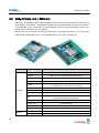

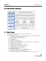

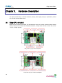


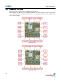

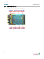


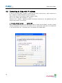

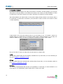


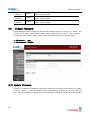


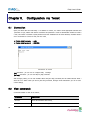
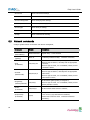


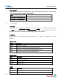


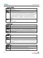

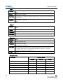


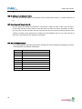
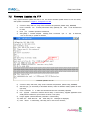


![[P/N: MCB3101] Class I Serial Bluetooth Wireless](http://vs1.manualzilla.com/store/data/005819698_1-328d04723caa8571829b907b8cc9e0c6-150x150.png)