1
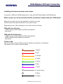
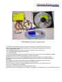
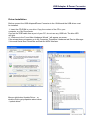
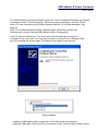
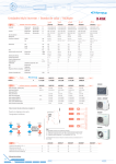
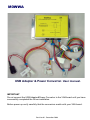
M0WWA
USB Adapter & Power Converter. User manual.
IMPORTANT
Do not connect the USB Adapter&Power Converter to the VNA board until you have
successfully completed the Driver installation.
Before power up verify carefully that the connectors match with your VNA board.
Revision 01. December 2008
M0WWA
USB Adapter & Power Converter
Assembly Manual
Installing the interconnection wire looms.
Connectors J160B and J360B assignments match with N2PK and Makarov,VE3IVM boards.
Before power up verify carefully that the connectors match with your VNA board.
Make the wire looms as short as possible to avoid pick up noise.
Left the wires looms apart each other for the same reason.
Depending on your VNA configuration you must connect as follows:
VNA with one detector:
- J160B, carrying control signals for DDS and detector1.
- Jpw, power
VNA with Dual detectors:
- J160B, carrying control signals for DDS and detector1.
- J360B, carrying control signals for detector2.
- Jpw, power.
Colour code.
The set includes coloured cables to help to identify pin numbers on connectors.
The resistor colour code is used as follows:
1- Brown
2- Red
3- Orange
4- Yellow
5- Green
6- Blue
7- Violet
8- Grey(or Gray)
9- White
10- Black
© M0WWA 2008. All rights reserved
USB Adapter & Power Converter
User manual.
USB Adapter & Power Converter set
The M0WWA USB adaptor&power converter is an option for N2PK VNA Windows users.
It allows to connect to a High Speed USB port on PC instead the parallel port, powering
at the same time the VNA.
The USB Adapter&Power Converter circuitry is divided on two main sections
- The USB High-Speed peripheral controller.
- DC/DC converters.
The USB High-Speed peripheral controller section is the same circuit that David Roberts G8KBB
designed and implemented to work with his program "My VNA".
It is based on Cypress CY7C68013A. Because by default the USB port only draws 100mA,
his software package includes the 500mA USB driver option needed by the USB configuration
descriptor.
Comprehensive technical information, drivers installation and updates can be found at:
http://g8kbb.roberts-family-home.co.uk/html/usb_interface.html
DC/DC converters, based on National LM3224 generate 5V and 12V to power the VNA
from the 5V available on the USB bus.
Decoupling, filtering and protection complement the circuit.
All tests has ben done with "My VNA" software on Windows XP and Windows Vista 32 operating systems.
A
C3
C4
100uH
100n
PolySwitch
0.5Amp
C6
100n
U1
CY7C68013A-56PVCX
4
3
DD+
2
3
16 D MINUS
15 D PLUS
4 -VUSB
R3
10K
Test Set SW0
Test Set SW1
DDS-FQ_UD
DDS W_CLK
49 RESET
R120
+5V
FB
L50
C51 R50
12 XT IN
5
MR
4
3 VDD
WDI
1
2K2
R52
C54
RP50
PolySwitch C55
0.5Amp
Pi Filter
Tuxonix
10uF 10uF
+5V
10uF
16V
RV3
10uF 10uF 2K2
68K
C52
1n5
+3V3
FB
C7
23-SDA
5V6 TransGuard
Voltage suppressor
U4
LT1117
C8
100n
22uF
C10 C11 C12 C13 C14 C15 C16 C17 C18 C19
C9
100n
22uF 100n 100n
100n 100n 100n 100n 100n 100n 100n
7 13 17 19 21 33 35 48
RESET
C2
PB0
C1
+3V3
12pF
R4 2K2
2
3
SOT 223
4
Vin
5
top
4
2
1
1 +VUSB
2 D3 D+
4 -VUSB
USB socket
Type B- Bottom view
A
8
1
4
6
5
9
8
7
10
PA5
Gnd
PB1
PA7
1
2
3
7
A0
SDA
6
SCL 5
2 A1
3 A2 WP 7
PB3
Gnd
PB2
PB7
Gnd
8
10
J360B
4
3
2
1
PA0
PB4
5
PA1
1
6
Atten1
3
4
Jpw
Atten0 Atten2
R2
2
SW0 SW1
+12V Gnd Gnd +5V
2K2
3K3
JP1
4
7
8
18
5
4
6
25
2
3
11
9
19
25
12
14
16
17
+12V
high brightness LED
5000 mcd.
(Front panel)
1
DB25 Parallel port connector pin correlation (N2PK VNA assignments)
Drawing
Approvals
Issued
Checked
Drawn M0WWA
* 45-PA5 - RF DDS Data & DET1 SDI - DET2 SDI
* 25-PB0 - DET1 SCLK & DET2 SCLK
B
USB adapter&Power converter
C
Size
A4
Scale
D
DWG No
Sheet 1/1
REV
Version
1.0
Date II IX MMVIII
4
4
3
1
3
PA5
J160B
R1
TPS2830-33
Vout
2
1
PB0
PA6
Gnd
PA4
PA2
match with connectors J160 & J360 on VE3IVM Makarov boards Jsp
U2
24LC64
LT1117
top
PA3
Gnd
PB5
3
3
12pF
Vout
RV2
14V TransGuard
Voltage suppressor
4
X1
24MHz
2 Gnd
Gnd
C53
C125
10uF
16V
FL
R51
U50
LM3224
22-SCL
U3
TPS3820-33
10uF
D50
10BQ040A
10uH
+USB
10uF
+12V
PolySwitch
0.5 Amp
Pi Filter
Tuxonix
C122
+USB
C50
C123 C124
R122
47K
1n5
Ground
11 XT OUT
33K
10uF 33K
10uF
DDS Reset
* see below
D120
R121
U120
LM3224
RP120
2
2
Connect to case(Earth)
+3V3
31-PB6
40-PA0
41-PA1
42-PA2
43-PA3
44-PA4
PW detect
C120 C121
45-PA5
46-PA6 LO DDS Data
47-PA7 ADC1 SDO
25-PB0 * see below
26-PB1 DET2 nCS
Atten0
27-PB2
Atten1
28-PB3
Atten2
29PB4
DET1 nCS
30-PB5
ADC2 SDO
32-PB7
1
2
+3V3
34 39 50
6 10 14 18 24
5V6 TransGuard
Voltage suppressor
1
10uH
FB
22uF/16
FL
10BQ040A
+USB
+USB
C5
RV1 +VUSB
USB socket
Type B
D
L120
RP1
J1
C
1
1
22uF/16v
B
L1
USB Adapter & Power Converter
User manual.
“MyVNA” software offers the following features:
• Reflection, Transmission or Dual detector scans
• S Parameter measurements with 5,6,10 or 12 term correction
• Automated Crystal Equivalent Circuit measurement
• Full transverter support
• Ability to load & store traces in multiple file formats
• Full set of display modes including Smith Charts and Polar displays
• Signal and sweep generator mode
• Integrated support for parallel and USB connection
• Runs under W98, ME, W2000, XP and Vista
• Basic, CDS, Harmonic Suppression and 3 / 5 harmonic modes
• Manual and automatic tracking markers with marker arithmetic
• Scans of up to 50,000 points per scan
• Averaging up to 10,000 readings per point
• Print & Windows clipboard copy support
• Switch and attenuator functions with manual or automated switching for S
parameter test set.
• Test mode for I/O lines in parallel or USB mode
• RF IV mode
• Logarithmic or linear scans and displays
• Drag & drop file import
USB Adapter & Power Converter
User manual.
“My VNA” software common configurations
Can’t get a trace on the screen? Check the settings. Here are a simple set to get you
going.
Instrument mode:
• Reflection or transmission mode is suggested initially
• Untick ‘Perform Reverse Scan’
• Untick ‘Use RF-IV mode’
• Untick ‘Always Do Dual Scan’
• Untick ‘Logarithmic Scan’
Display Sets
• Rs+Xs for transmission mode or G(dB)+<G for transmission. Choosing an
option under this heading means you can ignore for now Display Left and
Display Right
Display Options
• Tick ‘Graticule’
• Tick ‘Scan Progress Bar’
• Tick ‘Autoscale on display change’
• Tick both “snap” options
• Tick “Audio Cues”
• Tick “Invert RL display”
• Tick “Display Info Tips”
• Set vertical divisions to 8
• Set horizontal divisions to 10
• Set Print Pen Width to 5
• Set Display Pen Width to 2
• Untick ‘Smith/Polar View”
Calibration
• Tick ‘Use Separate ISO Average’
• Set Isolation Average to 5
• Tick ‘Response Calibration’
• Untick “Log Calibration Scan”
Reference Standards
• Set Cop to 0.04
• Set Cld to 0.23
• Set Rld to 50.00
• Set Lld to 0.15
• Set Rsh to 0.00
• Set Lsh to 0.00
Load & Store Data
• No specific settings
VNA Hardware
• If using single detector VNA set both ADCs to 1.
• If using dual detector set the ADCs according to you configuration
• Set ADC step delay to 1000
• Set Sweep Start Delay to 2000
USB Adapter & Power Converter
User manual.
• Set Phase change Delay to 0
• Set ADC Speed to 10 for a VNA with 2440 ADCs, or 1 for a VNA with
2410s
• Set Trace Average to 1
• Set clock to 148.343 initially (set it for your hardware later)
• Set Minimum frequency to 0.06 MHz
• Set Maximum frequency to 60 MHz
• Set System reference to 50.00
• From “hardware interface”, choose either USB or Parallel, choose
InpOut32 initially and check if using parallel that the port name and base
address are correct. Set the parallel port ADC timeout to 500 ms.
• From “Choose CDS/Harmonic mode” set “Harmonic Suppression Mode”
and “Fundamental” and “4 samples”
• Tick “Load DDS during ADC”
• Untick “Swap detectors on reverse scan” but remember this needs setting
correctly if you use an S parameter test set
Choose Trace Colours
• Choose suitable colours – not white !
Transverters
• Tick ‘none’
Network Settings
• Nothing to set in this version
Switches and Attenuators
• Select the configuration dialog and ensure all switches are enabled (you
may have to temporarily select the USB interface from “Hardware” to see
switch1)
• Ensure that for reverse scans, neither switch is ticked in the treeview
• Ensure that the “Set Attenuator Automatically” option is not ticked.
From the “View” menu select “Limits” and set the following
• DDS Clock Frequency Limits Min 10, max 10000
• Base VNA frequency limits to 0 (min) and 10000 (max)
• Transverter Frequency Limits 1 (min) and 10000 (max)
• Calibration standard limits 500 ( Rld) and 10 (the rest)
• Untick all the “Change LeftView Controls” boxes. If any were ticked, exit
the program and restart it to display the missing controls.
On the main toolbars:
• Select “Full Scan” from the drop down list
• Set Steps to 200
Now exit the program and restart it.
USB Adapter & Power Converter
User manual.
Driver Installation
Before connect the USB Adapter&Power Converter to the VNA board the USB driver must
be installed.
1- Insert the CD ROM in your drive. Copy the content of the CD in your
computer, e.g. My Documents.
Connect the USB cable from a port of your PC, do not use any USB hub. The blue LED
will light.
A “ Welcome to the Found New Hardware Wizard ” will appear on screen.
If the wizard does not appear go to My Computer/ Properties/ Hardware tab/ Device Manager
/ Universal Serial Bus Controllers and find the N2PK interface.
Mouse right button Update Driver... or
double click to get properties select driver
/ update driver.
USB Adapter & Power Converter
User manual.
Choose "No, do not connect to Windows Update" and click Next.
Choose "Install from a list or specific location" and click Next.
USB Adapter & Power Converter
User manual.
Choose "Search for the best driver in these locations", check "Include this
location" and Browse to the “USB N2PK VNA 500mA DRIVERS” subdirectory
in the file copied from the CD. Click OK and then click Next.
USB Adapter & Power Converter
User manual.
The 500mA N2PK drivers are installed. Ignore the "Has not passed Windows Logo Testing"
message and click "Continue Anyway". When the process completes, click the "Finish"
button. You are returned to the Windows desktop and the "Found New hardware" flag
pops up.
If the "Found New Hardware Wizard" appears again, repeat the process until
Windows can routinely find the USB interface when it is plugged in.
If the PC wants to reboot let it. The driver will in fact be working correctly but it
is simpler to get it over with. You may also find that if you plug it in to a different USB
port it wil reinstall the drivers again. This should only happen once per port.
Driver installed
Unplug the USB cable, place connectors on the VNA board and reconnect
again the USB cable. The blue LED on front panel is ON, now the VNA is ready to work.
USB Adapter & Power Converter
User manual.
Notes:
© M0WWA 2008. All rights reserved