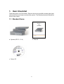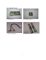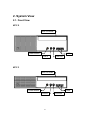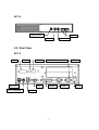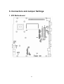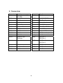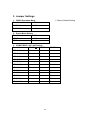
1
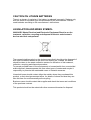
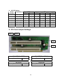
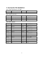
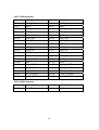
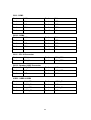
KPC 2 / 3 / 4 B72 User Manual P/N: 48201182 2006 September V1.2 Copyright 2006 September All Rights Reserved Manual Version 1.2 The information contained in this document is subject to change without notice. We make no warranty of any kind with regard to this material, including, but not limited to, the implied warranties of merchantability and fitness for a particular purpose. We shall not be liable for errors contained herein or for incidental or consequential damages in connection with the furnishing, performance, or use of this material. This document contains proprietary information that is protected by copyright. All rights are reserved. No part of this document may be photocopied, reproduced or translated to another language without the prior written consent of the manufacturer. TRADEMARK Intel®, Pentium® and MMX are registered trademarks of Intel® Corporation. Microsoft® and Windows® are registered trademarks of Microsoft Corporation. ELO Touch is the registered trademark of ELO Touch Systems. Safety IMPORTANT SAFETY INSTRUCTIONS 1. To disconnect the machine from the electrial power supply, turn off the power switch and remove the power cord plug from the wall socket. The wall socket must be easily accessible and in close proximity to the machine. 2. Read these instructions carefully. Save these instructions for future reference. 3. Follow all warnings and instructions marked on the product. 4. Do not use this product near water. 5. Do not place this product on an unstable cart,stand,or table.The product may fall, causing serious damage to the product. 6. Slots and openings in the cabinet and the back or bottom are provided for ventilation;to ensure reliable operation of the product and to protect it from overheating. These openings must not be blocked or covered.The openings should never be blocked by placing the product on a bed, sofa, rug, or other similar surface.This product should never be placed near or over a radiator or heat register,or in a built-in installation unless proper ventilation is provided. 7. This product should be operated from the type of power indicated on the marking label.If you are not sure of the type of power available, consult your dealer or local power company. 8. Do not allow anything to rest on the power cord. Do not locate this product where persons will walk on the cord. 9. Never push objects of any kind into this product through cabinet slots as they may touch dangerous voltage points or short out parts that could result in a fire or electric shock. Never spill liquid of any kind on the product. CE MARK This device complies with the requirements of the EEC directive 89/336/EEC with regard to “Electromagnetic compatibility” and 73/23/EEC “Low Voltage Directive”. FCC This device complies with part 15 of the FCC rules. Operation is subject to the following two conditions: (1) This device may not cause harmful interference. (2) This device must accept any interference received, including interference that may cause undesired operation. CAUTION ON LITHIUM BATTERIES There is a danger of explosion if the battery is replaced incorrectly. Replace only with the same or equivalent type recommended by the manufacturer. Discard used batteries according to the manufacturer’s instructions. LEGISLATION AND WEEE SYMBOL 2002/96/EC Waste Electrical and Electronic Equipment Directive on the treatment, collection, recycling and disposal of electric and electronic devices and their components. The crossed dustbin symbol on the device means that it should not be disposed of with other household wastes at the end of its working life. Instead, the device should be taken to the waste collection centers for activation of the treatment, collection, recycling and disposal procedure. To prevent possible harm to the environment or human health from uncontrolled waste disposal, please separate this from other types of wastes and recycle it responsibly to promote the sustainable reuse of material resources. Household users should contact either the retailer where they purchased this product, or their local government office, for details of where and how they can take this item for environmentally safe recycling. Business users should contact their supplier and check the terms and conditions of the purchase contract. This product should not be mixed with other commercial wastes for disposal. Table of Contents 1. Item Checklist ................................................................................................6 1.1. Standard Items........................................................................................6 1.2. Optional Items.........................................................................................7 2. System View ..................................................................................................8 2.1. Front View...............................................................................................8 2.2. Rear View ...............................................................................................9 3. Driver Installation ......................................................................................... 11 3.1. Driver List.............................................................................................. 11 3.2. Chipset Driver Installation ..................................................................... 11 3.3. USB2.0 Driver Installation.....................................................................13 3.4. VGA Driver Installation(Support Standard Resolutions & DVI / TV-Out)16 3.5. VGA IEGD Driver Installation(Supports 1366 x 768 Resolution) ..........17 3.6. Audio Driver Installation ........................................................................19 3.7. LAN Driver Installation ..........................................................................20 4. System Disassembly ...................................................................................21 4.1. Remove the Top Cover .........................................................................21 4.2. Replace the Heatsink and CPU ............................................................22 4.3. Replace the Motherboard .....................................................................24 4.4. Wall Mount Kits Installation ...................................................................27 4.5. COM Port Cables Installation (For KPC 2 / 3).......................................29 4.6. DVO Board Installation (For KPC 2 / 3) ................................................32 4.7. Replace the CF Adapter Card (For KPC 2 / 4)......................................33 4.8. KPC 2 ...................................................................................................34 4.8.1. Replace the 3.5” HDD and Slim CD-ROM ..................................34 4.8.2. Replace the PCI Riser Card (2 x Slots) ......................................35 4.8.3. PCI Card Installation...................................................................36 4.9. KPC 3 ...................................................................................................37 4.9.1. DDR Memory Installation ............................................................37 4.9.2. Replace the Slim CD-ROM and CF Adapter Card ......................37 4.9.3. Replace the Slim HDD and Slim CD-ROM .................................39 4.9.4. Replace the 3.5” HDD.................................................................41 4.9.5. Replace the PCI Riser Card (1 x Slot) ........................................41 4.9.6. PCI Card Installation...................................................................42 4.10. KPC 4 .................................................................................................43 4.10.1. Replace the Slim HDD..............................................................43 5. Specification.................................................................................................45 6. Connectors and Jumper Settings.................................................................47 7. Connector Pin Definition ..............................................................................51 8. BIOS Setting ................................................................................................54 Appendix A: PCI Card Dimension .......................................................................57 Appendix B: Wall Mount Kit Dimensions.............................................................59 Appendix C: Watch Dog Timer Programming Guide...........................................61 1. Item Checklist Take the system out of the carton. Remove the unit by carefully clutching the foam inserts and remove slowly to protect the system. The following contents should be found in the carton: 1.1. Standard Items a. System (KPC 2 / 3 / 4) b. Manual c. Driver CD 6 1.2. Optional Items a. DVO Board (1) b. CF Adapter Card (1) c. COM Port Cables (2) d. Wall Mount Kits (2) 7 2. System View 2.1. Front View KPC 2 Slim CD-ROM Power Button USB Line In Line Out KPC 3 Slim CD-ROM Power Button USB Line In 8 Line Out KPC 4 Power Button USB Line In Line Out 2.2. Rear View KPC 2 DVI Video S-Video 19V -IN PS/2 Keyboard VGA 2-Slot PCI Riser Card Parallel USB 9 COM 2 COM 1 LAN KPC 3 DVI Video S-Video 19V -IN VGA PS/2 Keyboard 1-Slot PCI Riser Card Parallel COM 2 COM 1 LAN USB KPC 4 PS/2 Keyboard 19V -IN USB VGA COM 1 Parallel COM 2 LAN Note: The maximum current that can be drawn from each COM port is 500 mA. 10 3. Driver Installation 3.1. Driver List Folder/File File Description <CD>:\KPC_B72.htm B72 Driver List <CD>:\COMMON\INTEL\Chipset Chipset Driver <CD>:\COMMON\INTEL\USB20 USB 2.0 Driver <CD>:\COMMON\INTEL\VGA\i85x\Win2K_XP\alpha\v14.19. 50 <CD>:\COMMON\INTEL\VGA\i85x\Win2K_XP\alpha\IEGD5 1-FT2a <CD>:\COMMON\Ac97_codec\Realtek\ALC202A <CD>:\COMMON\Lan_driver\R8139_810x VGA Driver VGA IEGD Driver Audio Driver LAN Driver - The following procedures are for Windows 2000/XP, other platforms are similar. 3.2. Chipset Driver Installation a. Double click the “infinst_enu_6.0.1.1002” on the “My Computer” window. b. Click the “Next” button on the “Welcome” window. 11 c. Click the “Yes” button on the “License Agreement” window. d. Click the “Next” button on the “Readme Information” window. e. Click the “Finish” button and restart your system. 12 3.3. USB2.0 Driver Installation OS Requirements OS USB 2.0 requirements Windows XP USB 2.0 drivers are provided in Service Pack 1 (SP1) for Windows XP, which is available through Windows Update. Windows 2000 USB 2.0 drivers are available through Windows Update or Service Pack 4. Windows 98SE/Me USB 2.0 drivers are available on the Intel developer site. Windows 98 (Retail) Developers and OEMs should contact Orange Ware. For end-users, if your device does not ship with Windows 98 drivers, contact your device or system manufacturer. If USB 2.0 drivers are not available, your device will operate at USB 1.1 speeds Linux USB 2.0 support is available in kernel 2.4.19 or later development kernels, or in the 2.4.19 or later production kernel. More information. a. Right click the “My Computer” on the windows desktop and select “properties”. 13 b. Select “Hardware”Æ”Device Manager” on system properties. c. Select ”Other Devices” Æ “Universal Serial Bus (USB) Controller” Æ”Properties” in the Device Manager. d. Select “Device”Æ “Update Driver…” e. Click the “Next” button on the “Welcome” window. f. Select “Search for a suitable…”and click the “Next” button on the “Install Hardware Device Drivers” window. g. Select “Specify a location” and click the “Next” button on the “Locate Driver Files” window. 14 h. Press “Browse” to select driver and then click the “OK” button to next page. i. Click the “Next” button on “Driver Files Search Results” window. j. Click the “Finish” button to complete this process. k. Finished. 15 3.4. VGA Driver Installation (Support Standard Resolutions & DVI / TV-Out) a. Double click the “win2k_xp141950” on the “My Computer” window. b. Click the “Next” button on the “Intel (R) Chipset Graphics Driver Software – InstallShield (R) Wizard” window. c. Click the “Next” button on the “Intel (R) Graphics Media Accelerator Driver” window. d. Click the “Yes” button on the “Intel (R) Graphics Media Accelerator Driver” window. 16 e. Select “Yes, I will restart my computer now” and click the “Finish” button. 3.5. VGA IEGD Driver Installation (Supports 1366 x 768 Resolution) a. Select “Utilities” on the My Computer window. b. Double click the “Setup” button on the My Computer window. 17 c. Select “Installs driver and application files” and click the “Next” button on Intel ® Embedded Graphics Driver Setup. d. Select “I agree” and click the “Install” button on Intel ® Embedded Graphics Driver Setup. e. Click the “Continue Anyway” button on the Hardware Installation” window. f. Select “No, not this time” and click the “Next” button on the Found New Hardware Wizard window. g. Click the “Yes” button and restart your system. 18 3.6. Audio Driver Installation a. Double click the ”wdm_93631” on the My computer window. b. Click the “Next” button on the Welcome window. c. Click the “Continue Anyway” button on the Hardware Installation window. d. Click the “Finish” button and restart your system. 19 3.7. LAN Driver Installation a. Double click the ”Setup” on the “My Computer” window. b. Click the “Finish” button on the “Maintenance complete” window. c. Click the “OK” button and restart your system. 20 4. System Disassembly Chapter 4.1., 4.2. ,4.3. and 4.4. are valid for KPC 2/ 3/ 4. 4.1. Remove the Top Cover a. Remove the screws (2). b. Remove the screws (2). c. Remove the screw (1). d. Remove the top cover towards you. 21 4.2. Replace the Heatsink and CPU Remove the top cover as described in chapter 4.1. a. Disconnect the fan. b. Remove the screws (2). c. Remove the fan. d. Remove the screws (4) that secure on the heatsink. 22 e. Turn 180 degree to open the key lock. f. Remove the CPU. Notice Fan: Celeron M 1.3/1.5GHz, Pentium M 1.8GHz a. Fan, Heatsink b. CPU, Socket, Copper hex screw 23 Fanless: Intel ULV Celeron M 800MHz/1.0GHz, LV Pentium M 1.4GHz a. Heatsink b. CPU 4.3. Replace the Motherboard Remove the top cover, heatsink and CPU first as described in chapter 4.1., 4.2. a. Remove the screw (1) that secures on the I/O bracket. b. Remove the screw (1) that secures on the I/O bracket. 24 c. Remove the hex secures (8) to remove the I/O bracket. d. Remove the screws (2). e. Remove the screw (1). f. Remove the screw (1). g. Remove the screw (1) that secures on the motherboard. h. Remove the screws (3). 25 i. Remove the screws (2). j. Remove the six hex copper screw. k. There is a washer behind the six hex copper screw. l. Withdraw the motherboard towards you. 26 4.4. Wall Mount Kits Installation Please refer to wall mount kit dimensions in Appendix B. a. Mount the system to the flat surface. a. Place the wall mount kits (2) (one on each side) into two sides. b. Tighten the screws (4) (two on each side) as shown in the picture. c. Mount the system to the flat surface. 27 b. The typical height is approximately 7 mm to mount the system to the surface. a. Remove the screws (4) (two on each side). b. Place the wall mount kits (2) into two sides. c. Tighten the screws (8) (four on each side). d. Mount the system to the surface. 28 4.5. COM Port Cables Installation (For KPC 2 / 3) Remove the top cover and replace the slim HDD and slim CD-ROM as described in chapter 4.1 and 4.9.3. a. Remove the screw (1) that secures on the bracket. b. Remove the screw (1). c. Remove the bracket. d. Remove the screw (1) that secures the PCI bracket. 29 e. Remove the PCI bracket. f. Insert the COM port cables into the slot. g. Tighten the screw (1). h. Connect the cables (2) (Refer to 6. Connectors & Jumper Settings). i. Place the bracket into the position. j. Tighten the screw (1). 30 k. Tighten the screw (1). l. Remove the screws (2). m. Slide the front cover into the system. Assemble the slim HDD, Slim CD-ROM and the top cover. 31 4.6. DVO Board Installation (For KPC 2 / 3) Remove the top cover as described in chapter 4.1. a. Insert the DVO board into the I/O bracket. b. Tighten the hex screws (2). c. Tighten the screw with the ground cable. Then, connect the DVO cable (1). d. Connect the cable (1) on the motherboard. 32 4.7. Replace the CF Adapter Card (For KPC 2 / 4) Remove the top cover as described in chapter 4.1. a. Disconnect the cable. b. Slide the CF card out. c. Remove the screws (3) that secure on the board. 33 4.8. KPC 2 4.8.1. Replace the 3.5” HDD and Slim CD-ROM Remove the top cover as described in chapter 4.1. a. Disconnect the cables (2). b. Remove the screws (2). c. Remove the screws (2). d. Slide the CD-ROM towards you. 34 e. Disconnect the cables (2). f. Remove the screws (2). g. Slide the 3.5” HDD to remove it. 4.8.2. Replace the PCI Riser Card (2 x Slots) Remove the top cover as described in chapter 4.1. a. Remove the PCI cards towards you. b. Remove the screws (2). 35 c. Remove the PCI slot. 4.8.3. PCI Card Installation Remove the top cover as described in chapter 4.1. a. Remove the screws (2). b. Insert the PCI card. c. Insert the second PCI card. d. Tighten the screws (2). 36 4.9. KPC 3 4.9.1. DDR Memory Installation Remove the top cover as described in chapter 4.1. a. Install DDR Memory by inserting it into the slot. b. Push the card down gently until two metal latches on the side of the slot click into place. 4.9.2. Replace the Slim CD-ROM and CF Adapter Card Remove the top cover as described in chapter 4.1. a. Disconnect the cables (2). b. Remove the screw (1). 37 c. Remove the screw (1). d. Disconnect the cable. e. Slide the CF card out. f. Remove the screws (3) that secure on the board. 38 4.9.3. Replace the Slim HDD and Slim CD-ROM Remove the top cover as described in chapter 4.1. a. Disconnect the cables (2). b. Remove the screws (2). c. Remove the screws (2) to remove the slim CD-ROM. d. Disconnect the cable (1). 39 e. Remove the screw (1). f. Remove the screw (1) to remove the bracket. g. Remove the screws (2). h. Remove the screws (2) to remove the slim HDD. 40 4.9.4. Replace the 3.5” HDD Remove the top cover as described in chapter 4.1. a. Disconnect the cables (2). b. Remove the screws (2). 4.9.5. Replace the PCI Riser Card (1 x Slot) Remove the top cover as described in chapter 4.1. a. Remove the screw (1). b. Remove the PCI card towards you. 41 c. Remove the screws (2). d. Remove the PCI slot. 4.9.6. PCI Card Installation Remove the top cover as described in chapter 4.1. a. Remove the screw (1) that secures on b. Insert the PCI card into the slot. the bracket. Then, remove the bracket. 42 c. Tighten the screw (1). 4.10. KPC 4 4.10.1. Replace the Slim HDD Remove the top cover as described in chapter 4.1. a. Disconnect the cable (1). b. Remove the screws (2) that secure on the slim HDD. 43 c. Slide the slim HDD to remove it. 44 5. Specification Model Name KPC 2 KPC 3 Motherboard Model CPU Supports KPC 4 B72 Intel ULV Celeron M 800MHz/1.0GHz Intel ULV Celeron (fanless); up to Celeron M 1.3/1.5GHz, M 800MHz/1.0GHz Pentium M 1.8GHz (fanless) Chipset 852GM + ICH4 System Memory 1 x DDR SO-DIMM slot, up to 1GB Graphic Memory Share system memory 8 ~ 64MB BIOS AWARD BIOS Storage HDD ODD Solid State Disk 2.5" Slim 3.5” HDD HDD (Optional) 3.5" HDD 2.5" Slim HDD Slim N/A N/A CD-ROM Support Compact Flash Card by optional CF adapter card. Slim CD-ROM Expansion PCI Slot 2-slot PCI riser card 1-slot PCI riser card N/A External I / O Ports Front I / O USB 2 Audio Line in 1 Line out 1 Rear I / O PS/2 Keyboard 1, Optional Y-cable for Mouse USB Serial/COM Parallel 2 1 x RS-232 port, 1 x RS-232 / 422 / 485 port 2 x RS232 ports by COM3 / COM4 cable kits (For KPC2 / 3 Only) 1 LAN (10 / 100) 1 VGA 1 45 Rear I / O 2nd VGA Optional by DVI/ TV-out card N/A TV-Out Optional by DVI/ TV-out card N/A DC Jack 1 Control Indicator Power Button 1 Indicator LED Power LED, HDD LED Power Power Adapter Default 65W DC-19V Power Adapter; Optional DC-19V 90W Power Adapter. Option Wall Mount Kit 2 Environment EMC & Safety Operating Temperature Storage Temperature Operating Humidity 5% to 95% RH, Non-condensing Storage Humidity 5% to 95% RH, Non-condensing Dimension (W x D x H mm/inch) Weight (kg/lbs) N.W. Weight (kg/lbs) G.W. OS Support CE, FCC Class A, LVD 0 ~35°C -20 ~ 60°C 243 x 218 x 72 mm 243 x 218 x 50 mm 243 x 218 x 35 mm 9.6” x 8.6” x 2.8” 9.6” x 8.6” x 2.0” 9.6” x 8.6” x 1.4” 2.7kg / 6.0lbs 2.3kg / 5.0lbs 1.7kg / 3.8lbs 3.2kg / 7.1lbs 2.8kg / 6.1lbs 2.3kg / 4.9lbs Microsoft Windows XP Professional, Windows XP Embedded - This specification is subject to change without prior notice. 46 6. Connectors and Jumper Settings 1. B72 Motherboard 47 2. Connectors Connector CN1 CN3 Function Power Connector For 3.5" HDD Inverter Connector Connector Function COM2 COM2 DIMM1 SO-DIMM DDR Memory CN4 DVO Connector F4 CPU Fan Connector CN5 LVDS Interface F7 System Fan Connector CN6 PCI SLOT IDE1 3.5” IDE Device CN7 Hardware Reset IDE2 Slim HD or CD-Rom CN8 IrDA Connector PRN1 Parallel Port CN9 COM3 PS1 Keyboard & Mouse CN10 COM4 PWR1 19V Power Adaptor CN11 CD-IN Connector RJ45_1 LAN Connector CN12 Speaker & MIC USB1 USB Port 1 Connector CN14 USB Port 2 Power Switch USB2 USB Port 5 USB Port 6 CN15 Audio Line-In USB3 USB Port 3 CN16 Audio Line-Out USB4 USB Port 4 COM1 COM1 VGA1 VGA Port 48 3. Jumper Settings ◎ Factory Default Setting 1. CMOS Operation Mode Function JP3 CMOS Normal ◎ N/C CMOS Reset 1-2 2. Power Mode Setting Function JP5 ATX Power ◎ N/C AT Power 1-2 3. COM2 RS232 / 485 / 422 Setting Function RS485 RS232 ◎ JP2 (1-2) Short JP2 (3-4) Short JP2 (4-6) JP2 (5-7) Short Short JP2 (7-8) Short JP2 (9-10) JP1(1-2) JP1(3-4) RS422 Short Short Short JP1(5-6) Short JP1(7-8) Short JP1(9-10) Short JP1(11-12) Short 49 4. LCD ID Setting Panel Resolution Number 0 640 x 480 LVDS JP6 Bits Channel 1-2 3-4 5-6 7-8 18 Single SHORT SHORT SHORT SHORT 1 800 x 600 18 Single SHORT SHORT SHORT OPEN 2 1024 x 768 18 Single SHORT SHORT OPEN SHORT 3 1280 x 1024 24 Dual SHORT SHORT OPEN OPEN 4 1024 x 768 24 Single SHORT OPEN SHORT SHORT 5 800 x 600 24 Single SHORT OPEN SHORT OPEN 4. PCI Card Jumper Settings JP21 JP22 JP23 JP24 JP 22 SERIRQ / GPIO 21 JP 21 REQ#5 / GNT#5 Factory Default Setting 1-3, 2-4 Factory Default Setting JP 23 LPC Factory Default Setting 1-3, 2-4 JP 24 LPC 1, 3, 5 Factory Default Setting 50 1, 3, 5 7. Connector Pin Definition CN1 : Power Connector For 3.5" HDD Pin 1 +12V Pin 2 GND Pin 3 GND Pin 4 +5V CN3 : Inverter Connector Pin 1 +12V Pin 2 +12V Pin 3 +12V Pin 4 Back-light Enable Pin 5 Brightness Control Pin 6 GND Pin 7 GND Pin 8 GND CN4 : DVO Connector Pin 1 DVOC 11 Pin 2 DVOC_HSYNC Pin 3 DVOC 10 Pin 4 DVOC_VSYNC Pin 5 DVOC 9 Pin 6 GND Pin 7 DVOC 8 Pin 8 DVO_DETECT Pin 9 DVOC 7 Pin 10 DVOC_BLANK# Pin 11 DVOC 6 Pin 12 DVOC_FLDSTL Pin 13 DVOC 5 Pin 14 GND Pin 15 DVOC 4 Pin 16 DVI_MDVIDATA Pin 17 DVOC 3 Pin 18 DVI_MDVICLK Pin 19 DVOC 2 Pin 20 GND Pin 21 DVOC 1 Pin 22 DVOC_CLK# Pin 23 DVOC 0 Pin 24 DVOC_CLK Pin 25 +5V Pin 26 GND Pin 27 +5V Pin 28 +1.5V Pin 29 +5V Pin 30 +1.5V 51 CN5 : LVDS Interface Pin 1 LVDS_B0+ Pin 2 LVDS_A3+ Pin 3 LVDS_B0- Pin 4 LVDS_A3- Pin 5 GND Pin 6 GND Pin 7 LVDS_B1+ Pin 8 LVDS_CLKA+ Pin 9 LVDS_B1- Pin 10 LVDS_CLKA- Pin 11 GND Pin 12 GND Pin 13 LVDS_B2+ Pin 14 LVDS_A2+ Pin 15 LVDS_B2- Pin 16 LVDS_A2- Pin 17 GND Pin 18 GND Pin 19 LVDS_B3+ Pin 20 LVDS_A1+ Pin 21 LVDS_B3- Pin 22 LVDS_A1- Pin 23 GND Pin 24 GND Pin 25 LVDS_CLKB+ Pin 26 LVDS_A0+ Pin 27 LVDS_CLKB- Pin 28 LVDS_A0- Pin 29 GND Pin 30 GND Pin 31 +5V_LCDVDD Pin 32 +3.3V_LCDVDD Pin 33 +5V_LCDVDD Pin 34 +3.3V_LCDVDD Pin 35 +5V_LCDVDD Pin 36 +3.3V_LCDVDD Pin 37 +5V_LCDVDD Pin 38 +3.3V_LCDVDD Pin 39 +5V_LCDVDD Pin 40 +3.3V_LCDVDD CN8 : IrDA Connector Pin 1 +5V Pin 2 IrDA_RX Pin 3 IrDA_TX Pin 4 GND 52 CN9 : COM3 Pin 1 DCD# Pin 2 RX# Pin 3 TX# Pin 4 DTR# Pin 5 GND Pin 6 DSR# Pin 7 RTS# Pin 8 CTS# Pin 9 RI Pin 10 +5V CN10 : COM4 Pin 1 DCD# Pin 2 RX# Pin 3 TX# Pin 4 DTR# Pin 5 GND Pin 6 DSR# Pin 7 RTS# Pin 8 CTS# Pin 9 RI Pin 10 +5V CN11 : CD- IN Connector Pin 1 CDIN_L Pin 2 CDIN_REF Pin 3 CDIN_R Pin 4 CDIN_REF CN12 : Speaker & MIC Connector Pin 1 AMP_ORL Pin 2 GND Pin 3 GND Pin 4 AMP_ORR Pin 5 GND Pin 6 MIC1 USB2 : USB5 & USB6 Pin 1 +5V_USB4 Pin 2 USB20_P4- Pin 3 USB20_P4+ Pin 4 GND Pin 5 +5V_USB5 Pin 6 USB20_P5- Pin 7 USB20_P5+ Pin 8 GND 53 8. BIOS Setting 1. BIOS Setup Utility The BIOS setup defines how the system is configured. You need to run this program the first time you configure this product. You may need to run it again if you change the configuration. You need to connect a PC keyboard to the keyboard connector to run the BIOS setup utility. 2. Starting the BIOS Setup 1. Turn on or reboot this product. 2. Press the DEL key immediately after the product is turned on, or press the DEL key when the following message is displayed during POST (the Power on Self-Test). Press DEL to enter SETUP. 3. The main menu of the BIOS setup is displayed. 4. If the supervisor password is set, you must enter it here. 3. When a Problem Occurs If, after making and saving system changes with the Setup utility, you find that this product no longer boots, start the BIOS setup and execute the following. Load Optimized Defaults 4. BIOS Main Menu When the BIOS Main Menu is displayed, the following items can be selected. Use the arrow keys to select items and the Enter key to accept and enter the sub-menu. Note: The BIOS menu below is from B72 BIOS version. If you have a different BIOS version, the contents of the menu may different. 54 Standard CMOS Features Use this menu for basic system configuration. Advanced BIOS Features Use this menu to set the Advanced Features available on the system. Advanced Chipset Features Use this menu to change the values in the chipset registers and optimize the system’s performance. Integrated Peripherals Use this menu to specify your settings for integrated peripherals. Power Management setup Use this menu to specify your settings for power management. PnP/PCI Configurations This entry appears if your system supports Plug and Play and PCI Configuration. PC health status Displays CPU, System Temperature, Fan Speed, and System Voltages Value. Load Optimized Defaults Use this menu to load the BIOS default values, i.e., factory settings for optimal performance system operations. While Award has designed the custom BIOS to maximize performance, the factory has the option to change these defaults to meet their needs. 55 Set Supervisor Password Enables you to change, set, or disable the supervisor or user password. Set Password Change, set, or disable the password. It allows you to limit access to the system and to the setup, or just to the setup. Save & exit setup Save CMOS value changes to CMOS and exits setup. Exit without saving Ignores all CMOS value changes and exits setup. 56 Appendix A: PCI Card Dimension Maximum dimension of the PCI add-on card: Component Side: 124.5mm x 81mm x 13mm (W x D x H) (Picture 1) Picture 1: Component side 57 Maximum dimension of the PCI add-on card: Bottom Side: 124.5mm x 81mm x 3mm (W x D x H) (Picture 2) Picture 2: Bottom Side 58 Appendix B: Wall Mount Kit Dimensions Figure 1 shows the system and wall mount kit dimensions. Figure 1: System and Wall Mount Kit Dimensions (mm) 59 The typical distance between the wall and the bottom of the system is 7mm. Figure 3 shows the wall mount kit dimensions. Figure 2: Mounting Height (mm) (KPC3 shown) Figure 3: Wall Mount Kit Dimensions (mm) 60 Appendix C: Watch Dog Timer Programming Guide 1. Register Description CRF5 Bit3: Select WDT Count Mode =0 second =1 minute Bit7: 4 reserved Bit2: 1 reserved CRF6 (Default 0x00) Watch Dog Timer Time-out value. Writing a non-zero value to this register causes the counter to load the value to Watch Dog Counter and starts counting down. If Bit 7 and Bit 6 are set, any Mouse Interrupt or Keyboard Interrupt event will also cause the reload of a previously loaded non-zero value to Watch Dog Counter and starts counting down. Reading this register returns the current value in the Watch Dog Counter instead of the Watch Dog Timer Time-out value. Bit 7 – 0 = 0x00 Time-out Disable = 0x01 Time-out occurs after 1 second/minute = 0x02 Time-out occurs after 2 seconds/minutes = 0x03 Time-out occurs after 3 seconds/minutes ................................................ = 0xFF Time-out occurs after 255 seconds/minutes CRF7 (Default 0x00) Bit 7 : Mouse interrupt reset Enable or Disable = 1 Watch Dog Timer is reset upon a Mouse interrupt = 0 Watch Dog Timer is not affected by Mouse interrupt Bit 6 : Keyboard interrupt reset Enable or Disable = 1 Watch Dog Timer is reset upon a Keyboard interrupt = 0 Watch Dog Timer is not affected by Keyboard interrupt Bit5:0 reserved 61 2. Basic Process to Enter/Exit Watch Dog Timer Configuration Mode 2.1. Enter Watch Dog Timer Configuration Mode ; Write 87h to the location 4E twice. mov dx, 4Eh mov al, 087h out dx,al nop nop out dx,al ; Set Logical Device 8 mov dx,4Eh mov al, 07h ;;Logical Device selector out dx,al mov dx,4Fh mov al,08h ;;logical device 8 out dx,al 2.2. Exit Watch Dog Timer Configuration Mode mov dx, 4Eh mov al, 0AAh out dx,al 3. Register Setting Example Please follow the example procedure: Step 2.1 Æ Step 3.1 Æ Step 3.2 Æ Step 3.5 Æ Step 2.2 3.1. Set Watch Dog Timer Counter Mode by Second mov dx, 4Eh mov al, 0F5h ;select CRF5 out dx,al mov dx,4Fh in al,dx ;get original value and al,0F4h ;bit3=0, WDT count mode = second. ;Note: Must keep other bits value. out dx,al 3.2. Set Watch Dog Timer Counter Mode by Minute mov dx, 4Eh mov al, 0F5h ;select CRF5 out dx,al mov dx,4Fh in al,dx ;get original value or al,08h ;bit3=1, WDT count mode = minute. ;Note: Must keep other bits value. out dx,al 62 3.3. PS/2 Mouse Interrupt Reset Watch Dog Timer mov dx, 4Eh mov al, 0F7h ;select CRF7 out dx, al mov dx,4Fh in al,dx or al,80h ;Watch Dog Timer reset by mouse interrupt out dx,al 3.4. PS/2 Keyboard Interrupt Reset Watch Dog Timer mov dx, 4Eh mov al, 0F7h ;select CRF7 out dx, al mov dx,4Fh in al,dx or al,40h ;Watch Dog Timer reset by keyboard interrupt out dx,al 3.5. Set Watch Dog Timer Counter Value mov dx, 4Eh mov al, 0F6h ;select CRF6 out dx, al mov dx,4Fh mov al,xxh ;;set Time-out value here, xx=1~0FFh for Set Watch Dog Timer counter value out dx,al 3.6. Update Watch Dog Timer Counter Value Repeat step 3.3 to reset the Watch Dog Timer counter value to update the counter value. 3.7. Disable Watch Dog Timer Repeat step 3.3 to reset the Watch Dog Timer counter value to update the counter value. mov dx, 4Eh mov al, 0F6h ;select CRF6 out dx, al mov dx,4Fh mov al, 00h ; set 0 to disable Watch Dog function. out dx,al Notice: A demo tool is provided on the Driver Bank CD. 63