1
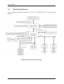
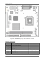
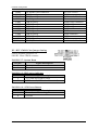
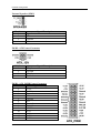
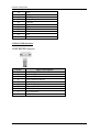
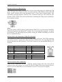
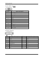
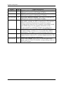
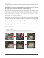
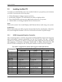
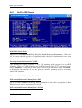
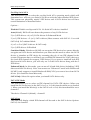
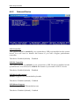
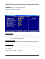
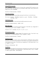
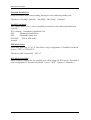
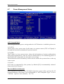
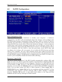
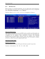
WADE-8134
Mini ITX Main Board
User's Manual
Version 1.1
Copyright © Portwell, Inc., 2006. All rights reserved.
All other brand names are registered trademarks of their respective owners.
Preface
Table of Contents
How to Use This Manual
Chapter 1 System Overview.......................................................................................................1-1
1.1 Introduction.................................................................................................................................. 1-1
1.2 Check List ..................................................................................................................................... 1-2
1.3 Product Specification .................................................................................................................. 1-2
1.3.1 Mechanical Drawing......................................................................................................... 1-5
1.4 System Architecture .................................................................................................................... 1-6
Chapter 2 Hardware Configuration ...........................................................................................2-1
2.1 Jumper Setting ............................................................................................................................. 2-1
2.2 Connector Allocation .................................................................................................................. 2-1
Chapter 3 System Installation....................................................................................................3-1
3.1 Socket 775 Processors.................................................................................................................. 3-1
3.2 Installing the Mini ITX................................................................................................................ 3-4
3.2.1 915GV Integrated Graphics Controller .......................................................................... 3-4
3.2.2 Dual Marvell Gigabit Ethernet controller ...................................................................... 3-5
3.2.3 Drivers Support ................................................................................................................. 3-5
Chapter 4 BIOS Setup Information............................................................................................4-1
4.1 Entering Setup.............................................................................................................................. 4-1
4.2 Main Menu ................................................................................................................................... 4-2
4.3 Standard CMOS Features ........................................................................................................... 4-2
4.4 Advanced BIOS Features............................................................................................................ 4-4
4.4.1 CPU Feature ....................................................................................................................... 4-4
4.4.2 Hard Disk Boot Priority.................................................................................................... 4-6
4.5 Advanced Chipset Features ....................................................................................................... 4-8
4.6 Integrated Peripherals .............................................................................................................. 4-11
4.6.1 OnChip IDE Device......................................................................................................... 4-12
4.6.2 Onboard Device............................................................................................................... 4-14
4.6.3 Super I/O Device ............................................................................................................ 4-15
4.7 Power Management Setup ....................................................................................................... 4-18
4.8 PnP/PCI Configurations .......................................................................................................... 4-21
4.8.1 IRQ Resources.................................................................................................................. 4-22
4.9 PC Health Status........................................................................................................................ 4-23
4.10 Frequency/Voltage Control................................................................................................... 4-24
4.11 Set Supervisor Password ........................................................................................................ 4-25
4.12 Set User Password ................................................................................................................... 4-26
Preface
How to Use This Manual
The manual describes how to configure your WADE-8134 system to meet various
operating requirements. It is divided into five chapters, with each chapter addressing
a basic concept and operation of Single Board Computer.
Chapter 1 : System Overview. Presents what you have in the box and give you an
overview of the product specifications and basic system architecture for this model of
single board computer.
Chapter 2 : Hardware Configuration. Shows the definitions and locations of Jumpers
and Connectors that you can easily configure your system.
Chapter 3 : System Installation. Describes how to properly mount the CPU, main
memory and flash disk to get a safe installation and provides a programming guide
of Watch Dog Timer function.
Chapter 4 : BIOS Setup Information. Specifies the meaning of each setup
parameters, how to get advanced BIOS performance and update new BIOS. In
addition, POST checkpoint list will give users some guidelines of trouble-shooting.
The content of this manual and EC declaration document is subject to change without
prior notice. These changes will be incorporated in new editions of the document.
Portwell may make supplement or change in the products described in this
document at any time.
Updates to this manual, technical clarification, and answers to frequently asked
questions will be shown on the following web site : http://www.portwell.com.tw
Notes :
(1) Memory type support dual-channel interleaved mode assuming DDR 400 MHz,
all DIMMs in a system must be of the same type, the speed in all channels is the
speed of the slowest DIMM in the system.
(2) The Power Supply must be support Ver 2.2 or Ver 2.3 or high version.
System Overview
Chapter 1
System Overview
1.1
Introduction
The WADE-8134 series all-in-one Mini ITX is designed to fit a high performance
Pentium 4 LGA 775 based processor and compatible for high-end computer system
application with PCI bus architecture. It is made to meet today’s demanding pace,
and keep complete compatibility with hardware and software designed for the IBM
PC/AT. The on-board devices support one PCI slot and integrated graphics and
on-board Dual Marvell Gigabit Ethernet controller. It’s beneficial to build up a high
performance and high data availability system for VARs, or system integrators.
WADE-8134 series support the following processors:
Intel® Pentium® 4 processor Socket LGA 775 supporting Hyper-Threading
technology based on 0.90 and 0.60 micron (CPUID = 0xh).(only support 5 series and
6 series)
Intel® Celeron D® processor Socket LGA 775 supporting Hyper-Threading
technology based on 0.90 and 0.60 micron (CPUID = 0xh). (only support 5 series and
6 series)
This Mini ITX can run with Intel Socket LGA 775 Pentium 4(HT) processors, and
support DIMM up to 2GB dual-channel DDR Memory. The enhanced on-board one
PCI-IDE interface can support 2 drives up to PIO mode 4 timing and Ultra
ATA33/66/100 synchronous mode feature, and 4 Serial ATA connectors high-speed
data transfers at up to 150 MB/s. The on-board Super I/O chipset support two serial
ports, one SIR (Serial Infrared) port, and one parallel port. Two high performance
16C550-compatible UARTs provide 16-byte send/receive FIFOs and the multi-mode
parallel port supports SPP/EPP/ECP function. Two RS-232 serial port interface.
Besides, H/W monitor function, and supports 4 Serial ATA interface , Intel High
Definition Audio as 7.1 surround sound , Hi-Speed USB 2.0 x 8 ports offer up to 40X
greater bandwidth over USB 1.1 Also provide dual display function by VGA and DVI
interface.
The Mini-ITX standard makes the WADE-8134 series work with the one slot PCI .
One 6-pin Mini-DIN connectors are provided to connect PS/2 mouse and keyboard.
The on-board Flash ROM is used to make the BIOS update easier. The high precision
Real Time Clock /calendar is built to support Y2K for accurate scheduling and
storing configuration information. One 24-pin standard connector is designed to
support ATX power function. A feature of CPU overheat protection will give user
more security and stability. All of these features make WADE-8134 series excellent in
stand-alone applications.
WADE-8134 User’s Manual
1-1
System Overview
Notes:
(1) The WADE-8134 series only support Intel Pentium 4 processor 5 series and 6 series
for 0.90 and 0.65 micron.
(2) The WADE-8134 series only support DDR 400 memory module.
1.2
Check List
The WADE-8134 package should cover the following basic items
One WADE-8134 Mini ITX Main Board
One 40pin IDE cable
Two Serial ATA cable
One Serial port cable for COM2
One I/O Shield bracket
One DVI and USB 2.0 cable optional
One CD-Title to support internal VGA display driver and Intel internal (or
Marvell Gigabit Ethernet) network controller driver
If any of these items is damaged or missing, please contact your vendor and keep all
packing materials for future replacement and maintenance.
1.3
Product Specification
Main processor
- Support Intel Pentium 4 processor (HT) up to 3.8GHz and above or Celeron D
processor up to 3.20GHz
- CPU bus clock : 533/800 MHz
Chipset Intel® 82915GV GMCH & 82801FR ICH6 (R)Main Memory
- Two 184-pin DIMM sockets
- 256 MB to 1GB using 256MB/512MB/1GB
- Dual-channel interleaved mode assuming DDR 400 MHz to 6.5GB/s
- Supports up to CL2 or 2.5 DIMMs at 400MHz memory bus.
System BIOS
- AWARD BIOS with PC’99 support
- FWH 4Mb Flash ROM for easy upgrades
- Support ACPI, DMI, PnP, and Green function
Super I/O Winbond W83627HF-AWLPC I/O
- Serial Ports : Support Two RS232 ports
- IrDA Interface : Support one Infrared port
- Parallel Port : Support one SPP, EPP/ECP bi-directional parallel port
WADE-8134 User’s Manual
1-2
System Overview
Storage IDE Interface
Support one enhanced IDE ports up to one IDE devices with Ultra DMA
33/66/100, Four Serial ATA connector high-speed data transfers at up to 150
MB/s.
USB
Support 8 x USB 2.0 ports
Keyboard and PS/2 Mouse Interfaces
Support two mini-DIN 6-pin connector for Keyboard and Mouse.
Auxiliary I/O
- One 2-pin system reset switch
- One 4-pin external speaker interface
- One 2-pin system power on LED
- One 2-pin HDD active indicator interface
- One 2-pin ATX power control interface
- One 4-pin smart fan for CPU cooler
- Two 3-pin headers for chassis and system fan
Real-Time Clock/Calendar (RTC)
- Build-in ICH6(R)
- Y2K compliant
Watchdog Timer
Set 0.6 ~600 sec. from ICH6 with GPIO 0~255 sec. with Super I/O chip
System Monitoring and Protection
- Monitoring system temperature, voltage, and cooling fan status
- Auto throttling control when CPU overheats
- System automatically restored on recovery of AC power loss
Bus Interface
- Follow Mini_ITX standard 6.69” x 6.69” (170mm x 170mm)
- Support one master of PCI slot
Wake On LAN & Modem Ring on
Support system wake up function from Network and Modem
On-chip 3D AGP VGA Display
- Integrated Intel Graphics Media Accelerator 900 (GMA900), and share system
memory to 224MB by Intel 82915GV
- Display core frequency of 333MHz
- One DSUB-15 connector for CRT display interface
- Support Maximum resolution up to 1600 x 1200, 32-bit colors for 3D at refresh
rates 85Hz
- Multiple Maximum overlay display resolution up to 2048 x 1536 32-bit
On-board DVI interface
Chrontel CH7307 transmitter with DF13-20DP
WADE-8134 User’s Manual
1-3
System Overview
On-board Ethernet Function
- Support Dual Marvell Gigabit Ethernet controller Support 10/100/1000BASE-T
with two RJ-45 interface ports
- Support two LED indicators to display active and link message
One PCI Interfaces
Support one extended PCI slot.
Physical and Environmental requirements :
- Outline Dimension (L x W) : 170mm (6.69 inch) X 170mm (6.69 inch)
- Power Requirements : [email protected] (typical), +12V@140mA, -12V@30mA
- Operating Temperature : 0 ~ 55 ℃
- Storage Temperature : -20~70℃
- Relative Humidity : 5% to 95%, non-condensing
WADE-8134 User’s Manual
1-4
System Overview
1.3.1
Mechanical Drawing
WADE-8134 User’s Manual
1-5
System Overview
1.4
System Architecture
All of details operating relations are shown in WADE-8134 series System Block
Diagram.
WADE-8134 System Block Diagram
WADE-8134 User’s Manual
1-6
Hardware Configuration
Chapter 2
Hardware Configuration
This chapter indicates jumpers’, headers’ and connectors’ locations. Users may find
useful information related to hardware settings in this chapter. The default settings
are indicated with a star sign (Ì).
2.1
Jumper Setting
In general, jumpers on the Mini ITX are used to select options for certain features.
Some of the jumpers are designed to be user-configurable, allowing for system
enhancement. The others are for testing purpose only and should not be altered. To
select any option, cover the jumper cap over (SHORT) or remove (NC) it from the
jumper pins according to the following instructions. Here, NC stands for “Not
Connect”.
2.2
Connector Allocation
I/O peripheral devices are connected to the interface connectors. (Figure 2-1)
WADE-8134 User’s Manual
2-1
Hardware Configuration
Figure 2-1 WADE-8134 Jumper and Connector Locations
Connector Function List
Connector
PANEL1 1-3
PANEL1 2-4
PANEL1 6-8
PANEL1 5-7
VGA
DVI
SPK1
IDE1
PWR1
Function
IDE1 active indicator
System Power On LED
System Power on Switch
System reset
DUB-15 port
DF13-20DP
External speaker interface
IDE1 (Primary) interface
24-PIN ATX Power connector
WADE-8134 User’s Manual
Remark
VGA connector
Hirose:DF13-20DP
2-2
Hardware Configuration
PWR2
COM1
COM2
PRT1
USB1
USB2
USB3
USB4
USB5
USB6
USB7
USB8
SPDIF I/O
PW-4P2R Power connector
COM1 serial port
COM2 serial port
Parallel port connector
USB 2.0 port 1
USB 2.0 port 2
USB 2.0 port 3
USB 2.0 port 4
USB 2.0 port 5
USB 2.0 port 6
USB 2.0 port 7
USB 2.0 port 8
SPDIF I/O interface
For CPU Power
COM1 connector
2x5 shrouded header
Printer connector
USB1LAN1 connector
USB1LAN1 connector
USB2LAN2 connector
USB2LAN2 connector
USB3 connector
USB3 connector
USB4 connector
USB4 connector
1x4 shrouded header
JP1 : RTC CMOS Clear Jumper Setting
OPEN: Normal operation
SHORT: Clear CMOS contents
PANEL1 5-7 : System Reset
Pin No.
7
9
Signal Description
Reset
Ground
PANEL1 1-3 : IDE1 active indicator
Pin No.
1
3
Signal Description
+5V (Pull-up for HDD LED)
HDD active# (LED cathode terminal)
PANEL1 6-8 : ATX Power Button
Pin No.
6
8
Signal Description
Power button control signal
Ground
WADE-8134 User’s Manual
2-3
Hardware Configuration
External Speaker (SPK1)
Pin No.
1
2
3
4
Signal Description
Signal
NC
Ground
+5V
PWR2 : ATX Power Connector
Pin No.
1
2
3
4
Signal Description
12V_Power
Ground
12V_Power
Ground
PWR1 : ATX_24P2R Power Connector
Pin No.
1
2
3
4
5
6
7
8
9
10
11
12
13
Signal Description
+3.3V
+3.3V
Ground
+5V
Ground
+5V
Ground
PW_OK
+5V SB
+12V
+12V
+3.3V
+3.3V
WADE-8134 User’s Manual
2-4
Hardware Configuration
14
15
16
17
18
19
20
21
22
23
24
-12V
Ground
PS ON
Ground
Ground
Ground
-5V
+5V
+5V
+5V
Ground
COM1/COM2 Interface
Pin No.
1
2
3
4
5
6
7
8
9
10
Signal Description
Data Carrier Detect
Received Data
Transmit Data
Data Terminal Ready
Ground
Data Set Ready
Request To Send
Clear To Send
Ring Indicator
Not used
WADE-8134 User’s Manual
2-5
Hardware Configuration
External USB3 & USB4 (USB2.0)
This mainboard provides 2 USB headers on the board allowing for 4 additional USB
ports. To make use of these headers, you must attach a USB bracket/cable with USB
ports (some models will come packaged with a USB 4-port bracket-cable). The
optionally packaged bracket will have two connectors that you can connect to the
headers (USB1, USB2). The other end (bracket containing the USB ports) is attached to
the computer casing.
Note :
If you are using a USB 2.0 device with Windows 2000/XP, you will need to install the
USB 2.0 driver from the Microsoft® website. If you are using Service pack 1 (or later)
for Windows® XP, and using Service pack4 (or later) for Windows® 2000,you will not
have to install the driver.
USB & (Gb) LAN Connectors: USB/ Gb LAN 1&2
This mainboard comes with 4 USB ports and a Gb/s LAN port. The USB connectors
are used to attach to keyboards, mice and other USB devices. You can plug the USB
devices directly into this connector. The LAN connectors can be attached directly to a
network.
Pin No.
1
2
3
4
Signal Description
TX+
TXRX+
NC
Pin No. Signal Description
1/5
+5 V (fused)
2/6
USBP0-/P1-
Pin No.
5
6
7
8
Signal Description
NC
RXNC
NC
Pin No. Signal Description
3/7
USBP0+/P1+
4/8
Ground
SATA1-4 (Serial ATA connector)
These SATA connectors (SATA1 – SATA4) support Serial ATA 150. Each SATA
connector can only support one serial ATA device. Note: With most storage devices,
there is a power cable that you need attach to a power source (power supply).
WADE-8134 User’s Manual
2-6
Hardware Configuration
Audio Port Connectors: Sound
Pin No.
1
2
3
4
Signal Description
SPO
VCC5
NC
GND
Audio in
Pin No.
1
2
3
4
Signal Description
CD-L
CD-GND
CD-GND
CD-R
Audio external for chassis
Pin No.
1
2
3
4
5
6
7
8
9
10
Signal Description
F_MIC1
GND
F_MIC2
VCC5
LOUTR
F_R
NC
NC
LOUTL
F_L
WADE-8134 User’s Manual
2-7
Hardware Configuration
Audio Jack
Pin No.
1(Blue)
2(Green)
3(Red)
Signal Description
Lin-in
Speak-Out
MIC-in
CPU FAN
Pin No.
1
2
3
4
Signal Description
Ground
+12V
RPM signal
Control
Chas_FAN / SYS_FAN
Pin No.
1
2
3
Signal Description
Ground
+12V
RPM signal
WADE-8134 User’s Manual
2-8
Hardware Configuration
Standard IrDA (KEY)
Pin No.
1
2
3
4
5
6
Signal Description
NC
Not Used
+5V
Ground
IRTX
IRRX
PS/2 Keyboard & Mouse (KBMS1)
Pin No.
1
2
3
4
5
6
Signal Description
Keyboard Data
Mouse Data
Ground
+5V
Keyboard Clock
Mouse Clock
WADE-8134 User’s Manual
2-9
Hardware Configuration
VGA D-SUB15 Connector
Pin No.
1
2
3
4
5
6
7
8
9
10
11
12
13
14
15
Signal Description
Red Signal
Green Signal
Blue Signal
NC
GND
GND
GND
GND
VCC
GND
NC
DCC_DATA
HSYNC
VSYNC
DCC_CLK
VGA DVI Connector
Pin No.
1
3
5
7
9
11
13
15
17
19
Signal Description
VCC5
GND
NC
NC
HPDET
MDVIDATA
MDVICLK
GND
TLC#
TLC
WADE-8134 User’s Manual
Pin No.
2
4
6
8
10
12
14
16
18
20
Signal Description
TDC0#
TDC0
NC
NC
TDC1#
TDC1
NC
NC
TDC2#
TDC2
2-10
Hardware Configuration
Signal
Type
TDC0,TDC0#
O
TDC1,TDC1#
O
TDC2,TDC2#
O
HPDET
I
TMDSDATA
I/O
TMDSDCLK
I/O
TLC,TLC#
O
WADE-8134 User’s Manual
Signal Description
DVI Data Channel 0 Output: These pins provide the DVI
differential output for data channel 0 (Blue).
DVI Data Channel 1 Output: These pins provide the DVI
differential output for data channel 1 (Green).
DVI Data Channel 2 Output: These pins provide the DVI
differential output for data channel 2 (Red).
Hot Plug Detect (internal pull-down): This input
determines whether the DVI is connected to a DVI monitor.
When terminated, the monitor is required to apply a
voltage greater than 2.4 volts. Changes on the status of this
pin will be relayed to the graphics controller via the
P-OUT/TLDET* or GPIO(1)/TLDET* pin pulling low.
DVI I2C Data: This signal is used as the I2C DOC clock for
a digital display connector (i.e. TV-Out Encoder, TMDS
transmitter). This signal is tri-stated during a hard reset.
DVI DOC Clock: This signal is used as the DOC clock for a
digital display connector (i.e. primary digital monitor). This
signal is tri-stated during a hard reset.
DVI Clock Output: These pins provide the differential
clock outputs to the DVI interface corresponding a data on
TDC(0:2) outputs.
2-11
System Installation
Chapter 3
System Installation
This chapter provides you with instructions on how to setup your system. The
additional information shows you how to install CPU/ FAN and memory.
3.1
Socket 775 Processors
Installing Pentium 4 / Celeron D CPU
1. Lift the handling lever of CPU socket outwards and upwards to the other end.
2. Align the processor pins with pin hones on the socket. Make sure that the notched
corner or
3. Dot mark (pin 1) of the CPU corresponds to the socket’s bevel end. Then press the
CPU gently until it fits into place. If this operation is not easy or smooth, don’t do
it forcibly. You need to check and rebuild the CPU pin uniformly.
4. Push down the lever to lock processor chip into the socket.
5. Follow the installation guide of cooling fan or heat sink to mount it on CPU
surface and lock it on the socket 775.
6. Be sure to follow particular CPU speed and voltage type to adjust the jumper
settings properly.
Having figured out in general what you get, the next job is to bite the bullet and build
your PC
Precautions
When integrating a Pentium 4 processor-based system, be sure to take the proper
electrostatic discharge (ESD) precautions. Consider using ground straps, gloves, ESD
mats, or other protective measures to avoid damaging the processor and other
electrical components in the system.
Warning
Do not touch socket sensitive contacts. Chain tech assumes no responsibility for the
potential damages caused by this action and therefore the warranty we provide may
be invalid.
WADE-8134 User’s Manual
3-1
System Installation
Installing CPU
#1 Disengage Load Lever by depressing down and out on the hook to clear retention
tab. Rotate Load Lever to fully open position at approximately 135°
#2 Rotate Load Plate to fully open position at approximately 100°. Remove Socket
Protective Cover. With left hand index finger and thumb to support the load plate
edge, engage protective cover finger tab with right hand thumb and peel the cover
from LGA775 Socket while pressing on center of protective cover to assist in removal.
#3 Locate the two orientation key notches.
#4 Grasp the processor with thumb and index finger. (Grasp the edges without the
orientation notches.) The socket has cutouts for your fingers to fit into. Carefully
place the package into the socket body using a purely vertical motion. (Tilting the
processor into place or shifting it into place on the socket can damage the sensitive
socket contacts.)
#5 Verify that package is within the socket body and properly mated to the
orientation keys
#6 Close the socket by
- Close the Load Plate
- While pressing down lightly on Load Plate, engage the Load Lever.
- Secure Load Lever with Load Plate tab under retention tab of Load Lever
WADE-8134 User’s Manual
3-2
System Installation
Installing Cooling Fan
Warning
For a safety landing, avoid leaving prongs on hard surface.
Instructions
Smear thermal grease on the top of the CPU. Lower the CPU fan onto the CPU/CPU
socket and secure it using the attachments or screws provided on the fan. Finally,
attach the fan power cable to the CPUFAN adapter. For more details on this, go to
http://www.intel.com
Main Memory
WADE-8134 series provides 2 DIMMs (184-pin Dual In-line Memory Module) to
support 2.6V DDRAM (Synchronized DRAM) as on-board main memory. The
maximum memory size is 256B~ 1GB with using 256MB/512MB/1GB technology.
Supports up to 2 double sided DIMMs at 266/333/400MHz. The memory
architecture adopts 128-bit data interface to support for x8 and x16 DDRAM(DDR1)
device width. In addition, it only supports Non-ECC memory.
For system compatibility and stability, don’t use memory module without brand.
You can also use the single or double-side DIMM .The three DIMMs can be out of
order. You can install different size of DDRAM module on DIMM1, DIMM2 or all to
boot up system.
Without out the contact and lock integrity of memory module with socket, it will
impact on the system reliability. Follow normal procedure to install your DDRAM
module into memory socket. Before locking, make sure that the module has been
fully inserted into the DIMM slot.
Note:
For maintaining system stability, do not change any of DDR memory parameters in
BIOS setup to upgrade your system performance without acquiring technical
information.
WADE-8134 User’s Manual
3-3
System Installation
3.2
Installing the Mini ITX
To install your WADE-8134 series into standard chassis or proprietary environment,
you need to perform the following steps:
1.
2.
3.
4.
Check all jumpers setting on proper position
Install and configure CPU and memory module on right position
Place WADE-8134 series into the dedicated position in your system
Attach cables to existing peripheral devices and secure it
Note:
Please refer section 3.4 to install display and Ethernet drivers and setup your system.
WARNING:
Please ensure that your SBC properly inserted and fixed by mechanism. Otherwise,
the system might be unstable or do not work from bad contact of golden finger.
3.2.1
915GV Integrated Graphics Controller
The on-board graphics controller integrated in 915GV(GMCH) chipset that integrates
high performance memory technology for the PCI Express x16, the on-board
operates at a frequency of 2.5Gb/s on each lane while employing 8b/10b encoding,
and supports a maximum theoretical bandwidth of 4Gb/s each direction, the
82915GV GMCH multiplexes the PCI Express interface with DVI & CRT support .
The 915GV supports the modes which appear in the table below.
Resolution
640x480
800x600
1024x768
1152x864
1280x600
1280x720
1280x768
1280x960
1280x1024
1400x1050
1600x900
1600x1200
1856x1392
1920x1080
1920x1200
Bits Per Pixel (frequency in Hz)
256 Color
16-bit
32-bit
60,70,72,75,85,100,120 60,70,72,75,85,100,120 60,70,72,75,85,100,120
60,70,72,75,85,100,120 60,70,72,75,85,100,120 60,70,72,75,85,100,120
60,70,72,75,85,100,120 60,70,72,75,85,100,120 60,70,72,75,85,100,120
60,75,85,100
60,75,85,100
60,75,85,100
60
60
60
60,75,85,100
60,75,85,100
60,75,85,100
60,75,85
60,75,85
60,75,85
60,75,85
60,75,85
60,75,85
60,75,85,100,120
60,75,85,100,120
60,75,85,100,120
60,75,85
60,75,85
60,75,85
60,75,85,100,120
60,75,85,100,120
60,75,85,100,120
60,75,85,100,120
60,75,85,100,120
60,75,85,100,120
60,75
60,75
60,75
60,75,85,100
60,75,85,100
60,75,85,100
60,75,85
60,75,85
60,75,85
WADE-8134 User’s Manual
3-4
System Installation
1280x1024
1920x1440
2048x1536
3.2.2
60,75
60,75,85
60,75
60,75
60,75,85
60,75
60,75
60,75,85
60,75
Dual Marvell Gigabit Ethernet controller
Dual Marvell Gigabit Ethernet 10/100/1000BASE-TX controller by PCI Express. The
WADE-8134 series provides two LED indicators on RJ-45 connector to show LAN
interface status. These messages will give you a guide for troubleshooting.
Yellow LED indicates transmit and receive activity.
Blinking : indicates transmit/receive activity
On : indicates no activity but link is valid
Off : link is invalid
Green LED
indicates Link speed
On : link speed at 1000Mbps
On : link speed at 100Mbps
Off : link speed at 10Mbps
3.2.3
Drivers Support
WADE-8134 series provides on CD-Title to support on-board VGA and Ethernet
device drivers in various operating systems. Before installing the device drivers,
please see the reference files in each sub-directory. You cannot install drivers from
CD-Title directly.
915GV CHIPSET INTEGRATED GRAPHY: Support Win2000, XP , Win2003 and 64bit
Windows … environment
INTEL 915GV & ICH6(R) CHIPSET DRIVER: Support Win2000 , XP , Win2003 and
64bit Windows … environment
Dual Marvell Gigabit Ethernet controller Support Win2000 , XP , Win2003 , and 64 bit
Windows ….. environment
WADE-8134 User’s Manual
3-5
BIOS Setup Information
Chapter 4
BIOS Setup Information
WADE-8134 series is equipped with the Phoenix (AWARD) BIOS stored in Flash
ROM. These BIOS has a built-in Setup program that allows users to modify the basic
system configuration easily. This type of information is stored in CMOS RAM so that
it is retained during power-off periods. When system is turned on, WADE-8134 series
communicates with peripheral devices and checks its hardware resources against the
configuration information stored in the CMOS memory. If any error is detected, or
the CMOS parameters need to be initially defined, the diagnostic program will
prompt the user to enter the SETUP program. Some errors are significant enough to
abort the start-up.
4.1
Entering Setup
Phoenix-Award BIOS has a built-in setup program that allows users to modify the
basic system configuration. This information is stored in CMOS RAM whose power is
supplied by a battery so that it can retain the setup information even when the power
is turned off. Press Delete when you Power on or Reboot the computer system. (i.e.
After the logo appears at the center of the screen, please press Delete to enter the BIOS
setup program). In the BIOS, make sure that everything is working fine before you try
to optimize it for maximum performance.
↑↓→ ←
Enter
+ / - /PU /PD
ESC
F1
F2
F5
F6
F7
F9
F10
General Help
: Move
: Select
: Value
: Exit
: General Help
: Item Help
: Previous Values
: Fail-Safe Defaults
: Optimized Defaults
: Menu in BIOS
: Save
WADE-8134 User’s Manual
4-1
BIOS Setup Information
4.2
Main Menu
When you enter the PHOENIX-AWARD™ CMOS Setup Utility, the Main will appear
on the screen. The Main allows you to select several configuration options. Use the
left/right arrow keys to highlight a particular configuration screen from the top
menu bar or use the down arrow key to access and configure the information below.
4.3
Standard CMOS Features
WADE-8134 User’s Manual
4-2
BIOS Setup Information
Date (mm/date/year) and Time (hh/mm/ss)
Allow you to change the date and time of the system clock. No matter how good the
quality of the motherboard, remember that losing (or gaining) several seconds per
month is not a surprising thing.
IDE Channel 0 Master/Slave
You can press Enter to see the submenus they contain.
Video
Allows you to select the type of displaying standard you are using. Available options
are EGA/VGA, CGA 40, CGA 80 and MONO.
Halt On
Select the situation in which you want the BIOS to stop the POST process and notify
you. Available options are All Errors, No Errors, All, but keyboard, All, but
diskette, and All, but disk/key.
Base Memory
Displays the amount of conventional memory detected during boot up.
Extended Memory
Displays the amount of extended memory detected during boot up.
Total Memory
Displays the total memory available in the system.
WADE-8134 User’s Manual
4-3
BIOS Setup Information
4.4
Advanced BIOS Features
4.4.1
CPU Feature
WADE-8134 User’s Manual
4-4
BIOS Setup Information
Delay Prior to Thermal
Select the delay thermal time. Configuration options: [4min][8min][16min][32min]
Thermal Management
This BIOS feature controls the activation of the Thermal Monitor's automatic mode.
It allows you to determine when the Pentium 4's Thermal Monitor should be
activated in automatic mode after the system boots. In general, the Thermal Monitor
should not be activated immediately on booting since the processor will be under a
heavy load during the booting process, which results in the sharp rise in die
temperature from its cold state, which leads to the unstable system. Therefore, to
ensure optimal booting performance, the activation of the Thermal Monitor must be
delayed for a set period of time. But how do you possibly know the optimal delay
time? It is recommended that you set this to its lowest value that exceeds the time it
takes to fully boot up your computer. This item will monitor the CPU thermal to
prevent the CPU damage from high temperature.
TM2 BUS Ratio
Select the Represents the frequency (bus ratio of the throttled performance state that
will be initiated when the on-die sensor goes from not hot to hot
TM2 BUS VID
Select Represents the voltage of the throttled performance state that will be initiated
when the on die sensor gose from not hot to hot.
Limit CPUID MaxVal
When the limit CPUID MaxVal is set to 3, the item should be set to “Disabled” for
Windows XP.
The choice: Enabled、Disabled (default).
C1E Function
Select CPU C1E Function Select
Execute Disable Bit
Select when disable, forces the XD feature flag to always return 0.
Virtualization Technology
Select when enable, a VMM can utilize the additional hardware capabilities provided
by Vander pool Technology
WADE-8134 User’s Manual
4-5
BIOS Setup Information
4.4.2
Hard Disk Boot Priority
Select
removable
device
priority,
such
as
Pri.Master,
USBHDD0 ,USBHDD1,USBHDD2 and Bootable Add-in Cards.
Pri.Slave,
Virus Warning
Allows you to choose the VIRUS warning feature for IDE Hard Disk boot sector
protection. If this function is enabled and someone attempts to write data into this
area. BIOS will show a warning message on screen and alarm beep.
CPU L1 & L2 Cache
Cache memory is much faster than conventional DRAM system memory. These fields
allow you to enable or disable the CPUs Level 1 built-in cache and Level 2 external
cache. Both settings are left as Enabled to significantly enhance the performance of
your computer.
Hyper-Threading Technology
When you install a CPU featuring Hyper-Threading Technology, this item will allow
you to enable or disable the Hyper-Threading technology.
The choice: Disabled、Enabled (default).
WADE-8134 User’s Manual
4-6
BIOS Setup Information
Quick Power On Self Test
Enable this function to reduce the amount of time required to run the POST (Power
On Self Test). BIOS will save time by skipping certain tests during POST. It is
recommended that you disable this setting. Finding a problem during boot up is
better than loosing data during your work.
First/Second/Third Boot Device
Allow you to select the First, Second and Third Boot Device. If your computer is
newly constructed, the next thing you want to do is load the Operating System from
scratch, directly off its CD. Before that, you need to set the First Boot Device to the
CDROM. This instructs the BIOS to boot from the CD drive before trying to boot from
the hard drive, which is still blank.
Boot Up NumLock Status
This function defines keyboard's numberpad as number keys or arrow keys. If set at
On the number keys will be activated, if set at Off the arrow keys will be activated.
Typematic Rate Setting
When enabled, you can set the following two-typematic control items. When
disabled, the keyboard controller determines keystrokes arbitrarily in your system.
Typematic Rate (Chars/Sec)
The typematic rate sets the rate at which characters on the screen repeat when a key is
pressed and held down.
Typematic Delay (Msec)
The typematic delay sets how long after you press a key that a character begins
repeating.
APIC Mode
By enabling this option, “MPS version control for OS” can be configured. Disabled
is recommended.
MPS Version Control for OS
The 1.1 version is the older version that supports 8 more IRQs in the Windows NT
environment. Choose the new 1.4 version for Windows 2000 and Windows XP.
The choice: 1.4 (default)、1.1
OS Select For DRAM > 64MB
IBM’s relic. If your system's DRAM is larger than 64MB and you are running OS/2,
select OS/2 as the item value. Otherwise, set the item value to Non-OS/2 for all other
operating systems.
WADE-8134 User’s Manual
4-7
BIOS Setup Information
4.5
Advanced Chipset Features
DRAM Timing Selectable
This item determines DRAM clock/timing using SPD or manual configuration. Make
sure your memory module has SPD (Serial Presence Data), if you want to select the
“By SPD” option.
The choice: Manual、By SPD (default).
CAS Latency Time
CAS is short for column address strobe, which is a kind of signals. When the CPU
needs data from SDRAM, CAS signals will be sent via the CAS line to specify the
column where the data is needed. This controls the time delay (in clock cycles - CLKs)
that passes before the SDRAM starts to carry out a read command after receiving it.
This also determines the number of CLKs for the completion of the first part of a burst
transfer. In other words, the lower the latency, the faster the transaction.
Note that some SDRAM modules may not be able to handle the lower latency and
will become unstable and lose data. Therefore, set the DRAM CAS Latency Time to 2
for optimal performance if possible but increase it to 2.5 if your system becomes
unstable.
WADE-8134 User’s Manual
4-8
BIOS Setup Information
Interestingly, increasing the CAS latency time does have an advantage in that it will
enable the SDRAM to run at a higher clockspeed, thereby giving you an edge in
overclocking your system. So, if you hit a snag while overclocking, try increasing the
CAS latency time.
DRAM RAS# to CAS# Delay
This item allows you to select a delay time between the CAS and RAS strobe signals.
It only applies when DRAM is written to, read from, or refreshed. This field is
adjustable only when “DRAM Timing Selectable” is set to “manual”. This field is
locked when “DRAM Timing Selectable” is set to “By SPD” and is automatically
determined by the system.
The choice: 4、3、2
DRAM RAS# Precharge
This item allows you to select the DRAM RAS# precharge time. The ROW address
strobe must precharge again before DRAM is refreshed. An inadequate configuration
may result in incomplete data. This field is adjustable only when “DRAM Timing
Selectable” is set to “manual”. This field is locked when “DRAM Timing Selectable”
is set to “By SPD” and is automatically determined by the system.
The choice: 4、3、2
Precharge Delay
This item allows you to select DRAM Active to Precharge Delay. This field is locked
when “DRAM Timing Selectable” is set to “By SPD” and is automatically determined
by the system.
The choice: 8、7、6、5
System BIOS Cacheable
Enabling this function allows caching of the system BIOS ROM at F0000h-FFFFFh,
which results in better system performance. However, if any program writes to this
memory area, a system error may result. It is advisable to leave it in default setting.
Caching the system BIOS results in better performance than shadowing the system
BIOS.
Video BIOS Cacheable
Select “Enabled” to allow caching of the video BIOS which may improve
performance. If any other program writes to this memory area, a system error may
result.
The choice: Enabled, Disabled (default)
WADE-8134 User’s Manual
4-9
BIOS Setup Information
Memory Hole at 15M-16M
Enabling this function will reserve the memory address space between 15MB and
16MB for ISA expansion cards. However, it will also result in not allowing the system
to have access to memory above 16MB. Please note that some expansion cards require
this setting to be enabled. The default setting is Disabled. If Auto Configuration is
enabled, you must set the DRAM timing function to 60ns or 70ns, depending on the
type of DRAM you install.
Marvell gigabit LAN
This item allows you to enabled or disabled the LAN 1 or LAN 2 , Enable (default)、
Disabled
On-Chip Frame Buffer Size
This item allows you to setting the VGA memory form share system . Options:
1M(minimum)、8M(Maximum default)
DVMT Mode
DVMT/FIXED Memory Size
Boot Display
This item allows you to setting CRT monitor only or CRT with EFP(DVI) together
display.
BIOS write protection
WADE-8134 User’s Manual
4-10
BIOS Setup Information
4.6
Integrated Peripherals
WADE-8134 User’s Manual
4-11
BIOS Setup Information
4.6.1
OnChip IDE Device
IDE HDD Block Mode
Enabled is recommended for the best hard drive performance. Windows
NT 4.0 users should set this to Disabled unless they can confirm they have been
updated with a Service Pack that will work with it.
On-Chip channel0/channel1 PCI IDE
The mainboard chipset contains a PCI IDE interface with support for two IDE
channels. These two IDE channels are for IDE1 and SATA1/2/3/4 connectors use.
Select “Enabled” to activate the first and/or second IDE interface. Select “Disabled”
to deactivate the interface if you are going to install a primary and/or secondary
add-in IDE interface.
The choice: Enabled (default)、Disabled
IDE channel0/channel1 Master/Slave PIO
Set all of these to Auto and let the BIOS determine if each drive is capable of Ultra
DMA support, and its respective PIO mode.
IDE channel0/channel1 Master/Slave UDMA
Same as above.
OnChip Serial ATA Setting
WADE-8134 User’s Manual
4-12
BIOS Setup Information
On-Chip Serial ATA
This field allows you to select the on-chip Serial ATA operating mode which will
determine how will use your Serial ATA drives with the other standard IDE drives.
This system can physically attach 2 IDE drives and 4 SATA drives but will have
certain limitations as described below.
Options:
Disabled: Disable on-chip serial ATA. No Serial ATA devices installed.
Auto(default): BIOS will auto-detect the presence of any SATA devices.
2 (or 1) IDE drivers + 4 (or 3) SATA drivers
Enhanced Mode
2 (or 1) IDE drivers + 2 (or 1) SATA drivers (Must connect with SATA1 +3 or with
SATA2+4) Combined Mode
4 ( or 3 or 2 or 1)SATA drivers
2 (or 1) IDE drivers
SATA only
Disabled
Combined Mode: Windows® 98/ME can recognize IDE devices but cannot directly
recognize an SATA device and therefore you must use this mode to allow the SATA
device to simulate an IDE device by assuming the role of one IDE channel in the
system. This means that you will have one available IDE channel for 2 SATA drives to
use (each IDE channel can support 2 IDE drives). If you were to install all both IDE
drives and 4 SATA drives, you will only see 2 of the SATA drives along with the 2
IDE drives.
Enhanced Mode: In this mode, you can use all 6 hard disk drives (including 2 IDE
drives and 4 SATA drives). Note: You cannot use “Enhanced” mode with Windows®
98/ME. It only support to install Windows® 2000/XP if you want to boot from SATA
device. (It’s restriction from Microsoft.)
SATA Only: Select this option when you install SATA drives only.
PATA IDE Mode
This item allows you to select an IDE channel for PATA IDE devices. When you
install the SATA device(s) to the SATA1 or 3 or 1+3, this item should be set to channel
1. When you install the device(s) to the SATA2 or 4 or 2+4, this item should be set to
channel 0.
The choice: Channel 0 (default)、channel 1
SATA Port
This item will display which IDE channel will be used to the SATA device.Options:
SATA2, 4 is channel 1
WADE-8134 User’s Manual
4-13
BIOS Setup Information
4.6.2
Onboard Device
USB Controller
This option should be enabled if your system has a USB port installed on the system
board. You will need to disable this feature if you add a higher performance
controller.
The choice: Enabled (default)、Disabled
USB 2.0 Controller
This option should be enabled if your system has a USB 2.0 device installed on the
system board. You will need to disable this feature if you install a USB 1.1 device.
The choice: Enabled (default)、Disabled
USB Keyboard Support
Enables support for USB attached keyboards.
The choice: Disabled (default)、Enabled
USB Mouse Support
Enables support for USB attached mouse.
The choice: Disabled (default)、Enabled
WADE-8134 User’s Manual
4-14
BIOS Setup Information
Audio Device
This item allows you to control the onboard audio.
The choice: Auto (default)、Disabled
4.6.3
Super I/O Device
Power On Function
This option allows you to select a way to power on your computer.
The choice: Password、Hot KEY、Mouse Left、Mouse Right、Any KEY、BUTTON
ONLY (default), and Keyboard 98.
KB Power On Password
This it the password that your system will use as part of the power-on sequence. This
field is only configurable when “Power On Function” is set to “Password”.
Hot Key Power ON
This option allows you to use the Ctrl key along with a hot key (function key) to
power on your system. This field is only configurable when “Power On Function” is
set to “Hot Key”.
The choice: Ctrl-F1、Ctrl-F2…… Ctrl-F12
WADE-8134 User’s Manual
4-15
BIOS Setup Information
Onboard FDC Controller
Select “Enabled” if your system has a floppy disk controller (FDC) installed on the
system board and you wish to use it. If you install an add-in FDC or the system has no
floppy drive, select “Disabled”.
The choice: Enabled (default)、Disabled
Onboard Serial Port 1
Select an address and corresponding interrupt for the first/ second serial port.
The choice: Disabled 、 3F8/IRQ4 (default for port1) 、 2F8/IRQ3 、 3E8/IRQ4 、
2E8/IRQ3、Auto.
UART Mode Select
This item allows you to select the Infra Red (IR) standard to be used.
The choice: Disabled (default)、ASKIR、IrDA
RxD, TxD Active
This item determines the RxD and TxD frequencies. This field only configurable if
“UART Mode Select” is set to “ASKIR” or “IrDA”.
The choice: Hi / Lo (default)、Hi / Hi、Lo / Hi、Lo / Lo
IR Transmission Delay
This item allows you to enable/disable IR transmission delay. This field is only
configurable if “UART Mode Select” is set to “ASKIR” or “IrDA”.
The choice: Enabled (default)、Disabled
UR2 Duplex Mode
Select the transmission mode used by the IR interface. Full-duplex mode permits
simultaneous bi-directional transmission. Half-duplex mode permits transmission in
only one direction at a time. This field only configurable if “UART Mode Select” is set
to “ASKIR” or “IrDA”.
The choice: Half (default)、Full
Use IR Pins
Consult your IR peripheral documentation to select the correct setting of the TxD and
RxD signals. This field is only configurable if “UART Mode Select” is set to “ASKIR”
or “IrDA”.Options: RxD2、DxD2 (default)
WADE-8134 User’s Manual
4-16
BIOS Setup Information
Onboard Parallel Port
Select an address and corresponding interrupt for the onboard parallel port.
The choice: 378/IRQ7 (default)、278/IRQ5、3BC/IRQ7、Disabled
Parallel Port Mode
This option allows you to select a parallel port mode for the onboard parallel port.
Options:
ECP (default) Extended Capabilities Port.
EPP
Enhanced Parallel Port.
SPP
Standard Printer Port.
ECP+EPP
Normal
ECP & EPP mode.
EPP Mode Select
Select EPP port type 1.7 or 1.9. This field is only configurable if “Parallel Port Mode”
is set to “EPP” or “ECP+EPP”.
The choice: EPP 1.9(default)、EPP 1.7
ECP Mode Use DMA
Select a DMA Channel for the parallel port when using the ECP mode. This field is
only configurable if “Parallel Port Mode” is set to “ECP”. Options: 3 (default)、1
WADE-8134 User’s Manual
4-17
BIOS Setup Information
4.7
Power Management Setup
ACPI Suspend Mode
This item specifies the power saving modes for ACPI function. Available options are:
1. S1 (POS)
The S1 state is low power state. In this state, no system context (CPU or Chipset) is
lost and the hardware maintains all system contexts.
2. S3 (STR)
The S3 state is a lower power state, where the information of system configuration
and opened applications / files are saved to main memory. The remaining power of
other hardware components are turn off to save energy.
The information stored in memory will be used to restore the system when a wake up
event occurs.
3. S1 & S3
If S3 state is supported by the system, by default [S3] is automatically selected.
Otherwise [S1] is selected.
Run VGABIOS if S3 Resume
Select whether you want to run VGABIOS when the system wakes up from the S3
suspend function. This field is not configurable if “ACPI Suspend Type” is set to
“S1(POS)”. Options: Auto (default)、Yes、No
WADE-8134 User’s Manual
4-18
BIOS Setup Information
Power Management
The level of power management can be set. Disable if you don't want any of it. You
can use min or max settings that are pre-determined, or set to "User Define" to
specify.
Video Off Method
Blank Screen: The system BIOS will only blank off the screen when disabling video.
V/H SYNC + Blank: In addition to Blank screen, BIOS will also turn off the V-SYNC
& H-SYNC signals from VGA cards to monitor.
DPMS: Select this option if your monitor supports the Display Power Management
Signaling (DPMS) standard of the Video Electronics Standards Association (VESA).
Use the software supplied for your video subsystem to select video power
management values.
Note:
Green monitors detect the V/H SYNC signals to turn off it's electron gun.
Video Off In Suspend
This determines whether power to the monitor is switched off when the computer is
in suspend mode. Options: Yes、No (default)
Suspend Type
This item allows you to select the suspend type under the ACPI operating system.
The choice: Stop Grant (default)、PwrOn Suspend
Modem Use IRQ
This determines the modem’s IRQ.
The choice: 3 (default)、4、5、7、9、10、11、NA.
Suspend Mode
This item allows you to select the suspend time under the ACPI operating system.
The choice: Disabled(default)、1Min、2Min、4Min、8Min、12Min、20Min、30Min、
40Min、1Hour
HDD Power Down
It shuts down any IDE hard disk drives in the system after an idle period. This feature
does not affect SCSI hard drives. Disabled is recommended.
WADE-8134 User’s Manual
4-19
BIOS Setup Information
Soft-Off by PWRBTN
When set to Delay 4 Sec., this function allows the power button to put the system in
Suspend, a power saving mode. When set to Instant-Off, the Soft-Off by PWR-BTN
function is disabled and the computer turns completely off when the power button is
pressed.
Wake Up by PCI card
If you highlight the “Wake Up by PCI card” label and then press the Enter key, it will
display a submenu with the following options:.
Power On by Ring
When enabled, a Modem/LAN will be able to receive a signal and activate the
system from soft off and green mode. You should connect the modem to the COM
port and signal your PC to power on.
USB KB Wake-up from S3
Allows the activity of USB device to wake up the system from S3 power saving
modes. Settings are Enabled and Disabled.
Resume by Alarm
When “Enabled”, you can set the date and time at which the RTC (real-time clock)
alarm awakens the system from Suspend mode.
The choice: Enabled、Disabled (default).
Date (of Month) Alarm
You can choose which date of the month the system will boot up. This field is only
configurable when “RTC Wake Up” is set to “Enabled”.
Time (hh:mm:ss) Alarm
You can choose the hour, minute and second the system will boot up. This field is
only configurable when “RTC Wake Up” is set to “Enabled”.
Reload Global Timer Events
When a system goes into suspend mode, certain devices must be inactive for a period
of time. Conversely, if any of those devices have any activity, the system will awaken.
You can select the devices that will participate in suspend/power-on activity by
configuring these fields. Devices include: Primary IDE 0/ Primary IDE 1/ Secondary
IDE 0/ Secondary IDE 1/ FDD, COM, LPT Port/ PCI PIRQ [A-D] #.
The choice: Disabled (default), Enabled
WADE-8134 User’s Manual
4-20
BIOS Setup Information
4.8
PnP/PCI Configurations
Reset Configuration Data
If you just install a new hardware or modify your computer ' s hardware
configuration, the BIOS will automatically detect the changes and reconfigure the
ESCD(Extended System Configuration Data). Therefore, there is usually no need to
manually force the BIOS to reconfigure the ESCD. However, the occasion may arise
where the BIOS may not be able to detect the hardware changes. A serious resource
conflict may occur and the operating system may not even boot as a result. This is
where the Reset Configuration Data BIOS feature comes in. This BIOS feature allows
you to manually force the BIOS to clear the previously saved ESCD data and
reconfigure the settings. All you need to do is enable this BIOS feature and then
reboot your computer. The new ESCD should resolve the conflict and allow the
operating system to load normally. Please note that the BIOS will automatically reset
it to the default setting of Disabled after reconfiguring the new ESCD. So, there is no
need for you to manually disable this feature after rebooting.
Resources Controlled By
This BIOS feature determines if the BIOS should automatically configure IRQ and
DMA resources. The BIOS is generally capable of automatically configuring IRQ and
DMA resources for the devices in your computer. Therefore, it is advisable that you
set this feature to Auto. However, if the BIOS has problems assigning the resources
properly, you can select the Manual option to reveal the IRQ and DMA assignment
fields. You can then assign each IRQ or DMA channel to either Legacy ISA or
PCI/ISA PnP devices. Legacy ISA devices are compliant with the original PC AT bus
specification and require a specific interrupt and/or DMA channel to function
properly. PCI/ISA PnP devices, on the other hand, adhere to the Plug and Play
standard and can use any interrupt or DMA channel.
WADE-8134 User’s Manual
4-21
BIOS Setup Information
4.8.1
IRQ Resources
When resources are controlled manually, you can assign each system interrupt a
type, depending on the type of device using the interrupt. This is only configurable
when “Resources Controlled By” is set to “Manual”.
The choice: IRQ-3/ 4/ 5/ 7/ 9/ 10/ 11/ 12/ 14/ 15 assigned to PCI device
PCI / VGA Palette Snoop
This option is only useful if you use an MPEG card or an add-on card that makes use
of the graphics card's Feature Connector. It corrects incorrect color reproduction by
"snooping" into the graphics card's framebuffer memory and modifying
(synchronizing) the information delivered from the graphics card's Feature
Connector to the MPEG or add-on card. It will also solve the problem of display
inversion to a black screen after using the MPEG card.
PCI Express relative items
Maximum Payload Size
This item allows you to set the PCI Express Maximum payload size per time.
The choice: 4096 (default)、128、256、512、1024、2048
WADE-8134 User’s Manual
4-22
BIOS Setup Information
4.9
PC Health Status
Case Open Warning
If this function is set to “Enabled” and the case had been previously opened, the
system will automatically display alert messages on the screen when you power on
your computer. If this function is set to “Disabled”, the system will not show alert
messages when you power on your computer even if the case had been previously
opened.
The choice: Disabled (default)、Enabled
Smart CPUFAN Temperature
This function allows you to select the CPU temperature. If the CPU temperature is
higher than the value you’ve selected, the CPUFAN will accelerate till the
temperature cools down to the defaulted value you set.
The choice: Disabled (default)、30oC / 86oF、35oC / 95oF、40oC / 104oF、45oC / 113oF、
50oC / 122oF、55oC / 131oF、60oC / 140oF、65oC / 149oF、70oC / 158oF、
75oC / 167oF、80oC / 176oF、85oC / 185oF
WADE-8134 User’s Manual
4-23
BIOS Setup Information
4.10
Frequency/Voltage Control
CPU Clock Ratio
This field will only display if the CPU has not been set to a locked state by the CPU
manufactory. If your CPU is locked, you will not be able to adjust the “CPU Clock
Ratio”. The default depends on your CPU. This item allows you to adjust your CPU
core voltage.
The choice: 0.85~1.9. The default depends on your CPU.
Auto Detect PCI Clk
This item is setting the PCI Clock be automation detect.
The choice: Enable(default) , Disable.
Spread Spectrum
The spikes generated by your motherboards clock generator create EMI
(Electromagnetic Interference). This function reduces the EMI by modulating the
pulses so that the spikes of the pulses are reduced and hence gives reduced EMI. But
this reduction can mean that some of your time-critical devices such as SCSI devices
can be affected and their stability reduced. Leave the setting disabled especially if
you are overclocking your system. If you find you have to try this use the smallest %
setting possible.
Some BIOS's have a Smart Clock setting which can turn off AGP, PCI & SDRAM clock
signals when not in use which reduces EMI without giving system stability problems.
This also gives a slight reduction in power consumption.
WADE-8134 User’s Manual
4-24
BIOS Setup Information
CPU Host /PCIEX/PCI Clock
This item displays the CPU Host frequency. You can set it from XXX to 333. The
default depends on your CPU frequency. The default for this field depends on the
CPU installed.
4.11
Set Supervisor Password
This feature consists of two options -- Set Password as well as Security Option. If
you set a password for security, the Security Option will enable you to determine
whether the code needs to be entered during the boot process or when you enter the
BIOS settings.
WADE-8134 User’s Manual
4-25
BIOS Setup Information
4.12
Set User Password
Load Fail-Safe Defaults
WADE-8134 User’s Manual
4-26
BIOS Setup Information
Load Optimized Defaults
Load System Default Settings
To avoid errors, this option allows you to recover the original defaults of BIOS. In
fact, this is the first skill you should know as you try to set other defaults of BIOS.
Load System Turbo Settings
This option has the similar function to the previous one. The difference between them
is that this is more efficient in settings, and this has the disadvantage of potentially
making the system unstable. So, the decision is up to you.
Load CMOS From BIOS
Load defaults from flash ROM for systems without batteries.
Save CMOS To BIOS
Save defaults to flash ROM for systems without batteries.SAVE to COMS and Exit
Save & Exit Setup
If you select this and type Y followed by Enter, the values entered in the setup
utilities will be recorded in the CMOS memory of the BIOS chip.
WADE-8134 User’s Manual
4-27
BIOS Setup Information
Exit Without Saving
Same as above, but without saving.
WADE-8134 User’s Manual
4-28