1
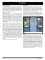
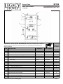
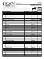
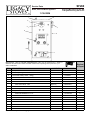
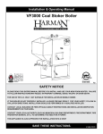
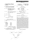
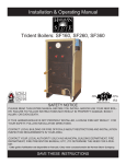
Installation & Operating Manual INSTALLER: Leave this manual with party responsible for use and operation. OwNER: Retain this manual for future reference. Call your dealer for questions on Installation, Operation, or Service. NOTICE: DO NOT discard this manual! wARNING Please read this entire manual before installation and/or use your new boiler. Failure to follow these instructions could result in property damage, bodily injury or even death. Model(s): Trident Boilers: SF160 & SF260 • Donotstoreorusegasolineorotherflammable vapors andliquidsinthevicinityofthisoranyother appliance. • Donotoverfire-Ifanyexternalpartstartstoglow,you areoverfiring.Reducefeedrate.Overfiringwillvoid yourwarranty. • Complywithallminimumclearancestocombustibles asspecified.Failuretocomplymaycausehousefire. Safety Notice IF THIS AHS BOILER IS NOT PROPERLY INSTALLED, A HOUSE FIRE MAY RESULT. FOR YOUR SAFETY, FOLLOw INSTALLATION DIRECTIONS. ! CAUTION Tested and approved for solid-fuel only (wood, coal). Burningofanyothertypeoffuelvoidsyourwarranty. ! CAUTION Checkbuildingcodespriortoinstallation. “Ce manuel est disponible en Français sur demande” • InstallationMUSTcomplywithlocal,regional,stateand nationalcodesandregulations. • Contactlocalbuildingorfireofficialsaboutrestrictions andinstallationinspectionrequirementsinyourarea. SAFETY NOTICE PLEASE READ THIS ENTIRE MANUAL BEFORE YOU INSTALL AND/OR USE YOUR NEw BOILER. FAILURE TO FOLLOw INSTRUCTIONS MAY RESULT IN PROPERTY DAMAGE, BODILY INJURY, OR EVEN DEATH. IF THIS AHS BOILER IS NOT PROPERLY INSTALLED, A HOUSE FIRE MAY RESULT. FOR YOUR SAFETY, FOLLOw INSTALLATION DIRECTIONS. CONTACT LOCAL BUILDING OR FIRE OFFICIALS ABOUT RESTRICTIONS AND INSTALLATION INSPECTION REQUIREMENTS IN YOUR AREA. CONTACT YOUR LOCAL AUTHORITY (SUCH AS MUNICIPAL BUILDING DEPARTMENT, FIRE DEPARTMENT, FIRE PREVENTION BUREAU, ETC.) TO DETERMINE THE NEED FOR A PERMIT. nstructions 3-90-70742R13_10/13 Rev 140912 Introduction TaBlEOFCOnTEnTS Packinglist 4 Installation aquastat Wiring Venting Plumbing 5 6 7 7 8 OperatingInstructions StartingaWoodFire StartingaCoalFire loadingFuel Shakingashes 10 10 11 11 11 SafetyTips 12 Maintenance 13 Specifications 13 Warranty 14 Servicelog 17 ServiceParts 18 = Contains updated information Legacy StovesTM Central Heating Appliances are built and tested to be complete Home Heating solutions. As with any Central Heat system, a backup heating system may be required in the event of power outages or during appliance service or maintenance. 3 3-90-70742R13_10/13 Rev 140912 Packing List Items needed for assembly and installation. Please notify your Legacy StovesTM Dealer if you are missing any items. Included with Boiler: --ShakerHandle --ashPan --WarrantyRegistrationForm Items In Boiler Kit # 1-00-01020: (Sold Separately) --JohnsonControlsaquastat-(3)pieces;a350Controllerw/Sensorwire S350StageModule Y350PowerSupply --ImmersionWell --DinRailand(2)EndClamps --TerminalBox --TerminalBlockand(2)#8-32nuts --PressureReliefValve(30psi.) --Temperature/PressureGauge --automaticDraftControlassembly --(1pc.)FlexConduitw/(2)90°Fittingsw/nuts,and(3)Chasenipplesw/nuts --(2)ManualDraftControlKnobassembly --(3)BrassCoilSpringHandle Appliance Certification. Model:TridentSeriesBoiler-SF160&SF260. Test Lab:Omni-Testlaboratories,Inc. Report #: 135-S-05-4 Type: Solid Fuel (Wood, Coal) Fired appliance for ResidentialUse Standard(s): Can/CSa B366.1-M87, and applicable sectionsofUl834andETlM78.1 Notice: The Aquastat controls supplied with the Boiler Kit are designed only to maintain water temperature within the boiler. The actual heating system is controlled separately by your thermostat(s) opening zone valves or energizing circulation pump(s). Do not attach a thermostat to the supplied controls. note:Thisapplianceisalsoapprovedforinstallationintoa shop. 4 3-90-70742R13_10/13 Rev 140912 Installation Getting Started Pressure Relief Valve The sheet metal sides and top are easily removed to reduce the chance of dents and/or scratches in the finish. Simply lift the top off, and that will allow the sides to be pulled away and up, for removal. To re-install, slide the channel, at the bottom of each side piece, over the lip at the bottom of the boiler, and hold downward while moving the side panel into place. Then slide the top down over the sides. NOTE: The sheet metal top holds the sides in place, thus, no bolts or screws are needed. ! Domestic Hot Water Coil Option Temp/Pressure Gauge Immersion Well Johnson Controls Aquastat and Terminal Block Optional Electric Back-up Elements CAUTION Boiler should not be installed closer than 18 inches (457 mm) to any combustible material Locating Boiler Place the boiler as close to the chimney as possible, while still maintaining the above mentioned clearances. Bolt the shaker handle on to the block on the side of the boiler, using the (2) 5/16 X 3/4 in. bolts and lock-washers. Assembly Shaker Handle Fig. 1 Automatic Draft Control Install the Temperature/Pressure Gauge into the pipe stub in the center of the round plate on the front of the boiler (Fig. 1) Install the A350 sensor wire all the way into the immersion well and screw the well into one of the top hole 3/8 to 1/2 in. Turn the pressure relief valve into the stub on top of the boiler, next to the supply outlet fitting. NOTE: Use Teflon tape to seal the threads on all fittings. Any unused fittings must be plugged Bolt the two manual draft controls through the holes in the top load door. (Fig. 2) The draft control knob should spin freely and open to a distance of approximately 3/8 in. from the door surface, while being able to close against the door surface. Fig. 2 5 3-90-70742R13_10/13 Installation Bolt the Automatic Draft Control through the 1/2 in. hole in the center of the bottom door. Be sure to hold the Draft Control straight while tightening. Feed the two wires from the draft motor through the flexible conduit and a 90˚ fitting. Secure the fitting to the draft motor and that end of the conduit at this time. Check the flapper door on the Automatic Draft Control assuring that it moves freely. Install the (3) brass coil spring handles onto the door latches and the shaker handle. Start the spring handle onto the shaft and twist it counter-clockwise while pushing. Aquastat Installation (See optional items, page 7) Lay the din rail on a flat surface, with the flat side down. Secure one end clamp, on the left side. Slide the A350 controller onto the rail from right to left until it is against the end clamp. Slide the Y350 onto the rail and guide the plug-in connector, joining it to the A350. Next, install the S350, again, guiding the plug-in connector carefully. Install the other end clamp to the right side of the din rail. Remove the covers from all three controls by loosening four screws each. Install the terminal box to the controls using (3) chase nipples and locknuts, supplied with the kit. Using the four holes in the terminal box, mount the terminal box and controls to the boiler sheet metal side as shown in Fig. 1. Using (2) #8-32 nuts, install the terminal block onto the studs located inside the terminal box. Wiring Diagram Fig. 3 6 3-90-70742R13_10/13 Installation wiring and Electrical Followingthewiringdiagram,runallwirestotheirdesignated connections. Save the main power for the last hook-up, andleavethebreakerintheoffposition.Thesensorwires attachtothea350Controllerontheterminalsmarked“sen” and“com”.Makesurethesensorissubmergedfullyintothe wellandsecuredwiththeset-screws. Setting The Aquastat Insidethea350control,youwillseeasquarejumper,and a differential dial. Be sure the jumper is in the “Heating” position. The differential dial is set to determine how low, below the temperature set point, you want the water temperature to go before the automatic Draft Control opens.agoodinitialsettingforthisdialis5°.Besurethe 120Vwiresareattachedtothecommonandthenormally openterminals,andreplacethecover.Theexternaldialis setforthewatertemperatureyouwishtomaintain,agood settingis180°. Inside the Y350 control, ensure that your wires are connectedtothe120VaCterminals,andreplacethecover. Inside the S350 control, which is used as overheat protection, you’ll see two dials; offset, and differential. Thereisalsoajumperwhich,inthiscase,getsplacedinthe “cooling”position.Theoffsetdialsetsthenumberofdegrees abovethea350setpointthatyouwanttheoverheatdump toactivate.agoodsetpointwouldbe20°.Thatwouldmean thatifthewaterreaches200°,usingthea350setpointof 180°,theS350wouldcloseit’scontactsandenergizethe overheatdumpzone.Thedifferentialdialsetsthepointthat theoverheatdumpwouldstop.Withthedifferentialsetat 15°, using the temperatures above, the circuit would reopen,stoppingtheoverheatdumpatawatertemperature of185°.The120Vwiringisattachedonthenormallyopen andthecommonposition.Thenormallyclosedpositionis notused. Fig. 4 Re-installthecoversontothethreeControls. 7 3-90-70742R13_10/13 Installation 3 feet (0.9m) above the point at which they exit from the roof, it must also extend 2 feet (0.6m) above the highest pointwithina10ft.(3m)radius. DO NOT CONNECT THIS UNIT TO A CHIMNEY FLUE THAT IS SERVING ANOTHER APPLIANCE. NOTE:Therestrictionofnotventingmorethanoneappliance tothesameflueappliestotheU.S. specifically.InCanada, CSaB365-01allowsit,withspecificrestrictions.Besureto contact your building code inspection official to see if this optionisallowedinyourarea,andtofindoutthespecific requirementsforsuchaninstallation. Plumbing TheLegacyTridentBoilercanbeusedasa“Standalone” boiler or as an add-on to an existing hot water heating system. The diagrams in this manual are meant to show the necessary equipment and piping. Your system may look very different. However, if configured properly, the same resultswillbeachieved. Fig. 6 shows a typical plumbing diagram for tying into an existing system. This method provides water circulation between the two boilers with a circulating pump. In this setup,thedomesticwatercoilintheexistingboilerwillbe heated,makingitunnecessarytoinstallawatercoilinthe TridentBoiler. Tying-intoanexistingboilermustbedoneinthereturnline between the circulator and the existing boiler. Run a pipe fromtheretoasmallcirculator,andthenintothe1-1/4in. fittingontherearoftheTridentBoiler.nextrunapipefrom the1-1/4in.fittingonthetopoftheTridentBoilertoaTee fittinginthesupplylineoftheexistingboiler.ThisTeefitting mustbeinstalledbetweentheexistingboilerandtheFlow Control Valve, as shown in Fig. 6.an air valve should be installedonthisline. Fig. 5 limitconnectorpipeto8ft.orless,withnomorethantwo elbows.allhorizontalsectionsshouldhave1/4in.riseper foot. The chimney must be capable of providing a draft reading of at least .06 in. of water column. a barometric damper can be installed to prevent excessive and erratic draft.allconnectorpipeshouldbesecuredwithsheetmetal screwsateachjoint. Air Valve Notice: The Aquastat controls supplied with the Trident Boiler are designed only to maintain water temperature within the boiler. The actual heating system is controlled separately by your thermostat(s) opening zone valves or energizing circulation pump(s). Do not attach a thermostat to the supplied controls. 8 Fig. 6 3-90-70742R13_10/13 Installation Thecirculatorinstalledbetweenthetwoboilersmaybehookeduptoruncontinuouslyduringtheheatingseasonor,an additionalS350control(notsupplied)couldbeinstalledtoturnitonandoffautomatically.Thiscontrolmustbeusedasa “closeonriseoftemperature”(jumperincoolingposition). Legacy StovesTM recommendsthat1-1/4in.pipebeusedbetweenthetwoboilers.alsorecommendedisthatthefirst sectionofpipeoffofthetopoftheTridentBoilerbethreadedgalvanizedorthreadedblack-steelpipe. TheLegacyTridentBoilerissuppliedwithadualfunctionaquastat.Thea350isusedtocontroltheautomaticdraftcontrol whetheropen,toincreaseheat,orclosed,todecreaseheat.TheS350isusedasoverheatprotection.Sinceawoodorcoal fireisstillproducingheatwhenthedraftisclosed,thisoverheatprotectionisrequired.YoucouldhavetheS350energize acirculatingpumporazonevalveseparatefromtheheatingsystem,oritcouldbehookedupsothatitflowstheheated waterthroughoutthesystem.Eitherway,itmustbeabletoflowawayfromtheboiler. Figure7showsatypicalschematicoftheTridentboilerasa“standalone”system.note;thecrossoverpipe(#12)isnot totallynecessarybutisrecommendedtoprovidecirculationwithintheboilerwhiletheheatingsystemissatisfied.Thiswill ensureaneventemperaturewithintheboiler.Thetemperingvalveshown(#10)istopreventexcessivetemperatureofthe domesticwater. Fig. 7 9 3-90-70742R13_10/13 Operation Automatic Draft Control Starting a Wood Fire The heat output is regulated by the automatic draft control on the bottom door. The electric motor (A) opens and closes the flapper door (B). Opening and closing the flapper door regulates the air flow into the firebox. Make sure the boiler and all piping is full of water and that all air has been purged from the system. The maximum air flow can be adjusted by turning the adjusting bolt (C). Turn counter-clockwise for more air, and clockwise for less air. Adjust this bolt only while the flapper door is in the closed position. Otherwise, motor damage could occur. Turn on electrical power to the boiler. This should cause the automatic draft control to open. The idle air adjuster (D) controls the minimum amount of air that enters the firebox. Adjustment is made by turning the adjuster vertical for zero idle air, or horizontal for maximum idle air. It is best to start out with a medium setting as shown in Figure 9. Never start a fire without water in the system. An explosion will occur. Open the ash pan door to allow free air movement. With the firebox door open, crumble approximately 8 sheets of newspaper and place on the grates. Lay some small kindling on top of the newspaper. Be sure this kindling is dry and no more than 3/4 in. in diameter. Layer the kindling in a crisscross type pattern, to allow maximum air flow. Next lay some larger pieces of wood on top of the kindling (approximately 2 in. diameter). Using a match or lighter, light the paper just inside the door. Close and latch the firebox door and allow the fire to burn a few minutes. After about five minutes, close the ash pan door and re-open the firebox door an inch or two, to allow the smoke to clear. Add 4 or 5 larger logs (about 4 in. diameter) to the well established fire and close the firebox door. Leave the ash pan door open for about five minutes only. Now open the firebox door using the same method as before, always closing the ash pan door before opening the firebox door. Now you can load the firebox to the desired level. You may load wood to the top of the firebox. Close and latch the door. The ash pan door may again be opened to speed the ignition process. Do not leave the boiler unattended with any door open. Fig. 8 After the wood is burning well, close the ash pan door. The automatic draft control will now regulate the fire, based on temperature demand. The idle air adjuster must be tuned to where the fire doesn’t go out during long periods with no demand. Experience will dictate the best setting for your installation. Normally, the two manual draft controls on the firebox door are kept closed while burning wood. Fig. 9 10 3-90-70742R13_10/13 Operation Starting a Coal Fire Loading Make sure the boiler and all piping is full of water and that all air has been purged from the system. Coal should never be added unless there is a reasonably hot fire. The coal bed should be bright and vigorous. If you have an active coal bed, full loads can be added at any time. If not, add new coal in layers, as described in starting a coal fire. Never start a fire without water in the system. An explosion will occur. Turn on electrical power to the boiler. This should cause the automatic draft control to open. Shaking the Grates Do not leave the boiler unattended with any door open. Shaking should be done only when there is a well-established fire. The frequency of shaking will depend on the degree of burning. Twice a day shaking is recommended. The best results are achieved with short, choppy strokes as opposed to long, even strokes. Full rocking of the grates may allow burning coal to fall into the ash pan. The amount of shaking is critical, too much can disrupt the fire bed, and too little will restrict air-flow. The proper amount of shaking is normally achieved when hot red coals first start to drop through the grates into the ash pan. When you have accumulated a substantial charcoal bed, start adding a thin layer of coal. Pea or Nut sized coal is better for starting than Stove coal. Every effort should be made to not let a coal fire burn down too low. This will cause the reloading process to be much longer, with a real good chance of losing the fire altogether. Open the ash pan door to allow free air movement. Use the same procedure as starting a wood fire except, do not load the larger diameter wood Use wood about 2 in. diameter maximum. This size will form a very hot charcoal bed in less time. Again, the ash pan door may be opened periodically to speed the ignition process. When the first layer is burning with some blue flame, continue to add thin layers of coal until there is a solid bed of burning coal. Let each layer burn a blue flame before adding another layer. Additional coal can be layered in until the bed is approximately 10 inches deep. By now, you should have the ash pan door closed, and the automatic draft control will continue to regulate the fire. The idle air adjuster may need to be set for slightly less air for coal than wood. Here again, experience will dictate the best setting. The maximum air bolt can be turned all the way “counter-clockwise” to allow for a quicker recovery. Never adjust this bolt with the flapper open. The two manual draft controls, on the firebox door, are used to allow secondary air to pass over the fire when burning coal. This helps to burn the gasses that are emitted from the coal as it is heated. Your setting for these draft controls should be between 1/2 and 1 complete turn from closed. Adjust both controls equally. 11 Do not shake or stir with a low fire. Open the ash pan door to get maximum air flowing into the firebox. Once burning is restored, close the ash pan door and add a layer of coal to the fire bed. Follow the instructions under Starting a Coal Fire. When the new coal is thoroughly ignited, and there is a substantial bed of hot coals, the grates may then be shaken. Ashes and Ash Removal Ashes should never be allowed to accumulate above the top of the ash pan. Ashes in contact with the bottom of the grates act as insulation, which intensifies the heat on the grates and causes them to sag or warp. Also, too much ash accumulation will restrict air-flow which will make fire maintenance more difficult. Place ashes in a sealed metal container, outside, until they are cooled enough for final disposal. Coal produces considerably more ash than wood, so the intervals between emptying are much shorter. 3-90-70742R13_10/13 Operation Safety Tips When opening the firebox door, it should be cracked, slightlyopen,forafewsecondstoallowairintoburnany gaseswhichmaybepresent.Thiswillalsoallowsmoketo bedrawnawayfromthedoor.Whenevertheashpandoor isopen,itshouldbeclosedbeforeopeningthefireboxdoor. The firebox should never be filled with excessive coal to wheretheflueexitisblockedorimpededinanyway. Burning coal produces Carbon Monoxide. If the flue exit is blocked, the Carbon Monoxide can be forced out of the boiler, into the room, with possible FATAL consequences. With the exception of start-up or freshening of the fire, or performingashremoval,theashpandoorshouldbekept closed. Never install a Legacy Trident Boiler into a chimney with a history of down-drafts. Keep Children Away - May Cause Serious Burns. CAUTION: All surfaces of the boiler are hot. Do not touch. Keep children away. Serious burns will result if touched. This is a heat producing appliance. DANGER: Fire Hazard, Do not use chemicals or flammable liquids to start or “freshen-up” a fire. Severe burns or a house fire may result. Do not burn Garbage, Gasoline, Thinners, Oil, Kerosene Etc. An explosion, a house fire or serious personal injury could result. Keep all such liquids well away from this boiler. During the first few hours of burning, a blue smoke may be observed rising from the boiler.This is the paint going throughthecuringprocess.Itisadvisabletoincreasethe amountoffreshairintheroomduringthisbreakinperiod. Thiscanbeachievedbyopeningdoorsandwindows.Don’t bealarmed,thisisnormalandwillonlylastashortwhile. Chimney Problems Not Enough Draft -Chimneyistoolow.Thegeneralrulefor chimneysis16feettall,andtwofeethigherthananything tenfeetaroundit. airmaybeleakinginaroundaloosefittingclean-outdoor. Toomanyelbowsinconnectorpipe,orseamsandjointsof connectorpipearenotsecuredproperly. Improperlysizedchimneyorstovepipe. Chimney may be blocked with creosote or bird nests or similarobstructions. Crackedordefectivechimneyflueorliner. Down Drafts - Trees or other topographical barriers may impedeonchimneyperformancecausingaircurrentstobe pusheddownwardintotheflue.Thiscanalsobecausedby neighboringbuildingsorotherchimneys. Creosote and condensation -Ifcreosoteorcondensation runsoutofthechimneyorstovepipe,checkthefollowing; Chimney cap or liner may be defective, Boiler may be positionedtoofarawayfromthechimneywhichwouldnot allow the chimney to warm, Wood being burned may be green or wet, Boiler may be over-sized for the residence causingittobeburnedonlowtoooften. Excessive Draft -Thiscanbecontrolledwithabarometric damperinthestovepipe. 12 3-90-70742R13_10/13 Maintenance Thespiralchamberisbasicallyself-cleaning.However,ifthereisadraftproblemandyouhavebeenburningwoodfora longtimewithlittledemand,thespiralchamberwillneedtobecleaned.Tocleanthespiralchamber,removethestovepipe andscrapeanycreosoteordebrisfromthetopandfrontofthechamber.Therearofthechambershouldnothavemuch accumulation.Ifitdoes,cleanitout. nOTE:1/4”to1/2”ofcreosoteinthespiralchamberisnormal. Thepipesinsidethefireboxwillaccumulatecreosoteifthedemandforheatistoolowwhenburningwood.1/8”to1/4” ofcreosoteisnormalonthepipesandfireboxwalls.Ifmorecreosotehasaccumulated,itshouldbescrapedoffofthese surfaces. nOTE:Creosoteinthefireboxcanbeburnedoffbyburningcoalforafewdays. Thefirebricksmaybecomecrackedduringthecourseofnormaloperation.acrackedbrickthatisstillinplace,isstilldoing itsjob,andneednotbereplacedimmediately.Ifabrickisbroken,andhasfallenoutofplace,itshouldbereplacedbefore anyfurtherburningoccurs.ThefirebricksusedintheTridentBoilerareavailableforreplacementfromyourLegacydealer. Gasketsonthedoorsaretheretoregulateairtothefirebox.Ifagasketisfailing,you’llnoticedifficultyincontrollingthefire. Inspectthegasketsregularly,andreplacewithLegacy StovesTMsuppliedmaterialonly. Specifications Heating Capacity (Square Feet) approximateBTUperhour(woodorcoal) aMPRating WaterCapacity(USGallon) Weight Hydro-PressureTested FireboxDimensions(inches) SF-160 2200 Max. SF-260 3200 Max. 90,000 130,000 40 40 25 32 640lbs 780lbs Yes Yes 16Wx22lx19H 18Wx26lx20H Recommendedloglength(inches) 19 23 DoorOpeningSize(inches) 11x13 13x13 OverallDimensions(inches) 23Wx23.5lx45H 26Wx27.5lx45.5H FlueSize(diameter) 6inch 7inch FlueHeight(topofflue) 37.5inches 38.75inches numberOfGrates(10lbs.Each) 4 5 WaterInletandOutletSize 1.25nPT 1.25nPT automaticDraftControl Yes Yes TypeOfFuel 13 aquastat Yes Yes Temperature/PressureGauge Yes Yes aSMEPressureReliefValve Yes Yes Yes Yes DomesticHotWaterCoil(optional) 4GPM 4GPM approximateBTUperhour(electricoption) 30,000 30,000 KilowattRating(electricoption) 9 9 3-90-70742R13_10/13 warranty AHS CENTRAL HEATING PRODUCTS LIMITED wARRANTY alternate Heating Systems,onbehalfofitsLegacy StovesTM brand(”AHS”),extendsthefollowingwarrantyforall Harman® furnaceandboilerproducts(“Products”)thatarepurchasedfromanAHSauthorizeddealer. warranty Coverage:Subjecttotheconditions,exclusionsandlimitationssetforthbelow,AHSwarrantstotheoriginal owneroftheProducts,andtoanytransfereetakingownershipoftheProductsatthesiteoforiginalinstallationwithintwo yearsfollowingthedateoforiginalpurchase,thattheProductswilloperatefreefromdefectsinmaterialandworkmanship undernormalconditionsanduse,asdescribedintheoperatinginstructionsfurnishedwiththeProduct,duringthewarranty perioddescribedbelow.AHSwill,atitsoption,repairorreplaceanyProductcoveredbythiswarrantythatisdeterminedto bedefectiveinmaterialorworkmanship. warranty Period:Thewarrantyperiodrunsforsixyears,exceptformechanicalandelectricalcomponents,whichare warrantedforthreeyears.Thewarrantyperiodbeginsontheearlierof:(i)thedateofinvoicefortheProduct;(ii)inthecase ofnewhomeconstruction,thedateoffirstoccupancyoftheresidenceorsixmonthsafterthedateofsaleoftheProduct byanAHSauthorizeddealer,whicheveroccursfirst;or(iii)thedate24monthsfollowingthedateofProductshipmentfrom AHS,regardlessoftheinvoiceoroccupancydate. warranty Conditions:ThiswarrantyappliesonlytoProducts:(i)installed,operated,andmaintainedasrecommended intheProductuser’smanual;(ii)purchasedthroughanAHSauthorizeddealer;(iii)whileremainingatthesiteoforiginal installation;and(iv)thathavenotbeenalteredafterleavingthefactory. How to File a Claim:ClaimsmustbemadewithinthewarrantyperiodtothedealerwhosoldtheProduct.Ifthatdealer cannotprovidethewarrantyservice,contactthenearestAHSauthorizeddealer.additionalservicefeesmayapplyifyou areseekingwarrantyservicefromadealerotherthanthedealerfromwhomyouoriginallypurchasedtheProduct.Travel andshippingchargesforpartsarenotcoveredbythiswarranty. warranty Exclusions: This warranty does not cover the following: (1) consumable and normal wear items, including, withoutlimitation,flameguides,grates,coalbars,afterburnerhoods,firebrick,gaskets,paint,glassdiscoloration,burnpot housing weldments, burnpot grate weldments (pellet or corn), burnpot front plates (pellet or corn), burnpot front plate locks,cornaugerextensions,ceramicinserts,andceramicinsertplates;(2)noisecausedbyminorexpansion,contraction or movement of parts; (3) damage resulting from: (i) failure to install, operate or maintain the Product according to the installationandoperatinginstructionsandlistingagentidentificationlabelfurnishedwiththeProduct;(ii)failuretoinstall theProductaccordingtolocalbuildingcodes;(iii)shippingorimproperhandling;(iv)abuse,misuse,continuedoperation with damaged, corroded or failed components, accident, or incorrectly performed repairs; (v) environmental conditions, inadequateventilation,negativepressureordraftingcausedbytightlysealedconstruction,insufficientmake-upairsupply, orhandlingdevicessuchasexhaustfansorforcedairfurnacesorothersuchcauses;(vi)useoffuelsotherthanthose specifiedintheoperatinginstructions;(vii)installationoruseofcomponentsoraccessoriesnotsuppliedwiththeProduct or authorized and approved in writing by AHS; (viii) modification of the product not expressly authorized and approved byAHSinwriting;or(ix)interruptionsorfluctuationsofelectricalpowersupplytotheProduct;(4)non-AHScomponents oraccessoriesusedinconjunctionwiththeProduct;(5)theProducts’capabilitytoheatadesiredspace;informationis providedtoassisttheconsumerandthedealerinselectingtheproperProductfortheapplication;considerationmustbe giventoProductlocationandconfiguration,environmentalconditions,insulationandairtightnessofthestructure;or(6) additionalorunusualutilitybillsincurredduetoanymalfunctionordefectinProducts. Limitations of Liability: Repair or replacement in accordance with the provisions of this warranty will be the owner’s exclusiveremedyforandwillconstituteAHS’ssoleobligationunderthiswarranty,underanyotherwarranty(expressor implied),orincontract,tortorotherwise.noemployee,agent,dealer,orotherpersonisauthorizedtogiveanywarrantyon behalfofAHS.TOTHEEXTEnTallOWEDBYlaW,AHSMaKESnOOTHERWaRRanTY,EXPRESSORIMPlIED, InClUDInGanYWaRRanTYOFMERCHanTaBIlITYORFITnESSFORaPaRTICUlaRPURPOSE.AHSWIllnOT BElIaBlEFORanYCOnSEQUEnTIalORInCIDEnTalDaMaGESaRISInGOUTOFDEFECTSInORUSEOFTHE PRODUCTS.Somestatesdonotallowexclusionsorlimitationofincidentalorconsequentialdamages,sotheselimitations maynotapplytoyou.Thiswarrantygivesyouspecificrights;youalsomayhaveotherrights,whichvaryfromstatetostate. Thedurationofanyimpliedwarrantyislimitedtothedurationofthewarrantyperiodspecifiedherein. 14 3-90-70742R13_10/13 Notes 15 3-90-70742R13_10/13 Notes 16 3-90-70742R13_10/13 Service & Maintenance Log Date Of Service 17 Performed By Description Of Service 3-90-70742R13_10/13 SF160 Service Parts wood, Coal fired Boiler 1-70-03233 1 Beginning Manufacturing Date: N/A Ending Manufacturing Date: Active 11 2 3 4 8 9 10 5 6 7 IMPORTanT: THIS IS DaTED InFORMaTIOn. Parts must be ordered from a dealer or Stocked at Depot distributor.Providemodelnumberandserialnumberwhenrequestingservicepartsfromyour dealerordistributor. ITEM DESCRIPTION COMMENTS PART NUMBER 1 SafetyReliefValve 3-10-77382 Y 2 Press/tempGauge-RearMount 3-10-78427 Y 3 aquastatSensorWell 3-10-935111 Y 4 StoveWaterPlate(6holes,1fitting) Post1199 1-10-08024 3-10-24758 Y Qty2req 4-00-00042 Y 4Sets 1-00-00036 Y 4-00-00197P Y Gasket,BoilerPlate 5 DoorHandle-Cast Doorlatch loadDoor-Cast DraftControlKnob-Cast 6 4-00-00109-1 1-10-01005 Y ShakerBarWeldment4-1/4” 1-10-02017W Y ShakerBlock 2-00-01037-1 Y ShakerBracket 2-00-01047B longShakerHandleWeldment 2-00-01037-2 Y 1-10-03375 Y DraftMotor120v 3-20-45338 Y DraftMotorMountBracket 2-00-01010B ashDoor-Cast 4-00-00200-1D ShakerHandleMount 7 Qty2req automaticDraftControlassembly additionalservicepartsonfollowingpage. 8/13 SF160 Service Parts Beginning Manufacturing Date: N/A Ending Manufacturing Date: Active IMPORTanT: THIS IS DaTED InFORMaTIOn. Parts must be ordered from a dealer or Stocked at Depot distributor.Providemodelnumberandserialnumberwhenrequestingservicepartsfromyour dealerordistributor. ITEM 8 DESCRIPTION COMMENTS PART NUMBER Pre1199 1-00-03500 Y Controllera350aa-2C Post1199 3-10-1350112 Y aquastatTerminalblock Post1199 1-10-03501a PowerSupplyY350R-1C Post1199 3-10-935071 Y StageModuleS350aa-1C Post1199 3-10-7350111 Y aquastatReplacementforWhiteRogers 9 SideJacketw/Hole 2-00-00315-15S 10 SideJacketwithoutHole 2-00-04124-15S 11 JacketTop 2-00-08128-15S aDCCover 2-00-01012P aDCHinge 3-31-01004 aquastatSensor/a350ControlaPPBC-25C Post1199 ashPan 3-10-2992225 Y 1-10-16027 Y BoilerCoilWasher Pkgof2 1-00-07007 BoilerElectricBack-upforJohnsonControls Post1199 1-00-01019 BoilerKitassembly Brick9”x4-1/2”x1-1/4”(6needed) Brickangles 1-00-01020 Pkgof7 1-00-900450125 Pkgof4 1-00-01138 Setofcutbrick Brick,fullskid 1-00-08124 414pcs 3-40-900450250 DinRail,8”,(forMountingControls) 3-31-01020 DinRailEndclamp 3-31-01021 DomesticCoilassembly 1-00-07006 DomesticCoilWaterPlate(8holes,1fitting,2nuts) 1-10-07006 Qty4req ElementCover(ForBackup) Gasket1/2”Rope(loadDoor&ashDoor) Y 3-40-900450-414 Brick,9”x41/2”x21/2”,(Usedwithreducer) DoorPins3/8x17/8 Y 4-30-00138b 1-10-01008S 20Ft GasketGlue,32oz 1-00-53500 Y 3-42-4583 Grate13in-Cast Qty4req 3-00-00207 Y GrateHolder-Cast Qty4req 3-00-00193 Y Gratelink-Cast 4-00-00205D Y non-electricBoilerKit(includesregulator&draftcontrol) 1-00-08012 DraftRegulatorTypeC-20(usewithnon-electrickit) 3-91-05000 non-electricDraftControlassembly 1-10-08013a SpringHandle Pkgof3 3-40-00086-3-3 TouchUpPaint,aerosol Black 3-42-7737 Y SF260 Service Parts Beginning Manufacturing Date: N/A Ending Manufacturing Date: Active wood, Coal fired Boiler Appliance 1-70-03236 1 10 2 3 7 8 9 4 5 6 IMPORTanT: THIS IS DaTED InFORMaTIOn. Parts must be ordered from a dealer or distributor.Providemodelnumberandserialnumberwhenrequestingservicepartsfromyour dealerordistributor. ITEM DESCRIPTION COMMENTS PART NUMBER Stocked at Depot 1 SafetyReliefValve 3-10-77382 Y 2 Press/tempGauge-RearMount 3-10-78427 Y 3 StoveWaterPlate(6holes,1fitting) 1-10-08024 4 DoorHandle-Cast 3-10-24758 Y Qty2req 4-00-00042 Y Doorlatch 4Sets 1-00-00036 Y DraftControlKnob-Cast Qty2req 4-00-00109-1 Gasket,BoilerPlate loadDoor-Cast FlapperWeldment17-1/2” 5 6 4-00-00195P 1-10-00407 1-10-01005 Y ShakerBarWeldment4-11/16” 1-10-02018W Y ShakerBlock 2-00-01037-1 Y ShakerBracket 2-00-01047B ShakerHandleMount 2-00-01037-2 Y 1-10-03375 Y longShakerHandleWeldment automaticDraftControlassembly DraftMotorMountBracket 2-00-01010B ashDoor-Cast 4-00-00200-1D DraftMotor120v 3-20-45338 additionalservicepartsonfollowingpage. Y 8/13 SF260 Service Parts Beginning Manufacturing Date: N/A Ending Manufacturing Date: Active IMPORTanT: THIS IS DaTED InFORMaTIOn. Parts must be ordered from a dealer or distributor.Providemodelnumberandserialnumberwhenrequestingservicepartsfromyour dealerordistributor. ITEM 7 DESCRIPTION aquastatReplacementforWhiteRodgers aquastatSensor/a350Controla99BC-25C COMMENTS Stocked at Depot PART NUMBER Pre1199 1-00-03500 Y Post1199 3-10-2992225 Y auastatTerminalBlock Post1199 1-10-03501a aquastatSensorWell Post1199 3-10-935111 Y Controllera350aa-2C Post1199 3-10-1350112 Y PowerSupplyY350R-1C Post1199 3-10-935071 Y StageModuleS350aa-1C Post1199 3-10-7350111 Y 8 SideJacketw/Hole 2-00-00327-15S 9 SideJacketwithoutHole 2-00-07002-15S TopJacket 2-00-08132-15S 10 aDCCover 2-00-01012P aDCHinge 3-31-01004 ashPan 1-10-25027 BoilerCoilWasher Pkgof2 1-00-07007 BoilerElectricBack-upforJohnsonControls(option) Post1199 1-00-01019 BoilerKitassembly Brick9”x4-1/2”x1-1/4”(8needed) 1-00-01020 Pkgof7 1-00-900450125 Brickangles 1-00-01138 SetofcutBrick 1-00-00842 Brick,9"x4-1/2"x2-1/2",(usedforReducer) Brick,FullSkid 414pcs Y 3-40-900450-414 3-31-01021 DinRail,8",(ForMountingControls) 3-31-01020 DomesticBoilerCoilassembly 1-00-07006 DomesticCoilWaterPlate(8holes,1fitting,2nuts) 1-10-07006 Qty4req ElementCover(ForBackup) FlapperHook Y 3-40-900450250 DinRailEndClamp DoorPins,3/8x17/8 Y 4-30-00138B 1-10-01008S Qty2req GasketGlue,32oz 2-00-01005B 3-42-4583 Gasket,1/2”Rope(loadDoor&ashDppr) 20Ft 1-00-53500 Y Grate15in-Cast Qty5req 3-00-00208 Y GrateHolder2-Cast Qty2req 3-00-00193 Y GrateHolder3-Cast Qty2req 3-00-00194 Y Gratelink5-cast 3-00-00205 Y non-electricBoilerKit(includesregulator&draftcontrol) 1-00-08012 DraftRegulatorTypeC-20(usewithnon-electrickit) 3-91-05000 non-electricDraftControlassembly SpringHandle Touch-upPaint,aerosol 1-10-08013a Pkgof3 3-40-00086-3-3 3-42-7737 Y Legacy Stoves - Advanced Design & Old Fashioned Value. TM (Signature of Boxer) Your premium quality hearth product designed and assembled by the experienced and skilled members at Legacy StovesTM in Harrisonville, PA USA.