1
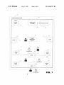
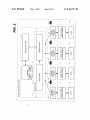
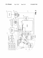
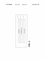
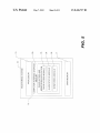
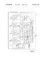
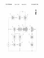
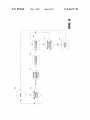
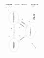
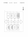
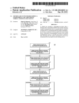
US008436727B2
(12) United States Patent
(10) Patent N0.:
(45) Date of Patent:
Todd et a1.
(54)
(56)
METHODS AND SYSTEMS FOR DOOR
ACCESS AND PATIENT MONITORING
US 8,436,727 B2
May 7, 2013
References Cited
U.S. PATENT DOCUMENTS
5,878,450 A
3/1999 Bouhuijs
(76) Inventors: James D. Todd, Garnett, KS (US);
Thomas Hollinger, Overland Park, KS
(US); Christopher F. FangroW,
Harrisonville, MO (US)
6,084,513 A
7/2000 Stoffer
6,134,725 A
10/2000 Bouhuijs
6,396,413 B2 *
5/2002
Hines et al. .................. .. 340/8.1
(Continued)
FOREIGN PATENT DOCUMENTS
Notice:
Subject to any disclaimer, the term of this
patent is extended or adjusted under 35
WO
W02010031694 A1
3/2010
OTHER PUBLICATIONS
U.S.C. 154(b) by 378 days.
TeleAlarm, NurseCall Main Unit, User Manual, 953.92, v1.0, dated
Aug. 2007 (92 pages).
(21) Appl. No.: 12/895,534
(Continued)
(22) Filed:
Sep. 30, 2010
Primary Examiner * Donnie Crosland
(74) Attorney, Agent, or Firm * Polsinelli Shughart PC
(65)
Prior Publication Data
US 2011/0128145 A1
(57)
Jun. 2, 2011
ABSTRACT
Methods and systems for door access and patient monitoring
are described. The patient monitoring system includes a door
access control system coupled to one or more doors of a
Related US. Application Data
facility for monitoring and controlling the access of patients
(60) Provisional application No. 61/247,327, ?led on Sep.
30, 2009.
(51)
(2006.01)
(2006.01)
(2006.01)
(2006.01)
(2006.01)
US. Cl.
USPC ............ .. 340/539.11; 340/539.12; 340/573.1;
340/539.23; 340/542; 340/5.2; 340/286.07;
340/5.7; 70/263
(58)
coupled to a patient monitoring device comes Within a pre
determined distance of a particular door the door access con
trol system transmits a ?rst signal encoded With the door
location data to the patient monitoring device. The patient
Int. Cl.
G08B 1/08
B60R 25/00
E05B 53/00
A61B 5/00
G05B 19/00
(52)
coupled to a patient monitoring device. Whenever a patient
Field of Classi?cation Search ........... .. 340/539.11,
monitoring device then transmits a second signal encoded
With the door location data and patient identi?cation data of
the patient coupled to the monitoring device to the door
access control system and a monitoring system that controls
the door access and monitoring of patient Within the facility.
If the door coupled to the door access control system is in the
open position When the patient is detected, the door access
control system transmits a third signal encoded With the door
location data to the monitoring system. The monitoring sys
tem then compares the door location data encoded in the
second signal With the door location data encoded in the third
signal before displaying that data at a master station for alert
ing facility staff.
340/539.12, 539.23, 542, 5.2, 286.07; 70/263
See application ?le for complete search history.
29 Claims, 11 Drawing Sheets
DOOR AOCRS wNTROL SYSTEM
(FIRST $3URCE)
Mommmns SYSTEM
(TNRD souace)
I
PATIENT MONITORING DEVICE
1
\
(SECOND SOURCE)
\
US 8,436,727 B2
Page 2
US. PATENT DOCUMENTS
6,972,660 B1 *
12/2005
6,972,677 B2
12/2005 Coulthard
7,554,446 B2 *
2004/0189471 A1*
2005/0052275 A1
2006/0235283 A1
2007/0163045 A1
6/2009
9/2004
Montgomery et al. .... .. 340/5.52
Ciarcia et al. ............ .. 340/568.1
Ciarcia et al. ............ .. 340/5721
3/2005 Houle
10/2006 Vinarov et al.
7/2007 Becker et a1.
OTHER PUBLICATIONS
2000 Series e/eM Style Keypad Installation and Programming
Manual, Document No. 6054022, Revision: 1.0, dated Dec. 21, 2006
TeleAlarm, IS 76 Beacon With Ferrite Antenna, Installation Manual,
Document 953.26 (11 pages).
Senior Technologies, WanderGuard Delayed Egress Magnetic
Locksi17000 Series (2 pages).
Senior Technolgoies, Arial Options, Wireless Communication Sys
tems, date unknown (1 page).
Senior Technologies, WanderGuard, Departure Alert System,
WanderGuard ID Departure Alert System, Model 16921, undated (2
pages).
Senior Technologies, WanderGuard System Hospital, Product Infor
mation, undated (1 page).
Information , Janvier 2006 Document No. 953-36 (4 pages).
Senior Technologies, Products and Services, undated (1 page).
Senior Technologies, WanderGuard System Long-Term Care, Prod
uct Information, undated (1 page).
Senior Technologies, WanderGuard System Residential Community,
Product Information, undated (1 page).
TeleAlarm, NurseCall Relay Unit, Data Sheet, Reference Nos.
NC.021.FI, XX, dated Jun. 3, 2006 (2 pages).
* cited by examiner
(60 pages).
TeleAlarm, LLC, LE9 Road (Resident Out-of-Bed Activity Module)
Speci?cation Sheet, date unknown (2 pages).
D. Schwendener, TeleAlarm, Wireless Contact RAC (434)iSet-up
US. Patent
May 7, 2013
Sheet 1 0f 11
US 8,436,727 B2
1a
If
.1“
.,..r,'._.._..,...
_....
..
.....
..
PATIENT MONiTDRlNG SYSTEM
FAG iLiTY
: .............................. ._\‘
SLAVE
um?
,
MGMTORING
SYSSTEM
"‘
= MASTER STATION
............... ..w...................,..........:
20
PATIENT
MGMTORiNG
DEVICE
Authszr'rzed User
22
DOOR
WALL
SLAVE
UNiT
FIG. 1
US. Patent
May 7, 2013
Sheet 4 0f 11
mwxiu
US 8,436,727 B2
US. Patent
May 7, 2013
Sheet 7 0f 11
US 8,436,727 B2
FALL-SAFE OPERATION SYSTEM
. 02
Q
92
2
o
Q2
3
$1
02Q23
92o02
0
A.
Strip
FIG. 7
US. Patent
May 7, 2013
Sheet 8 0f 11
US 8,436,727 B2
i
.N'ON
. i1. ,cz
US. Patent
May 7, 2013
Sheet 9 0f 11
US 8,436,727 B2
m.6?“
._ : A .
..1
»
Ux25O0J
:A..\.
EN; 1.
\.1...).
x042; wmOQ
US 8,436,727 B2
1
2
FIG. 7 is an electrical schematic diagram of the fail-safe
METHODS AND SYSTEMS FOR DOOR
ACCESS AND PATIENT MONITORING
operation system and supervisory unit for the patient moni
toring system;
FIG. 8 is a How chart illustrating the methods for patient
monitoring and door access for the patient monitoring sys
tem;
RELATED APPLICATIONS
This application takes priority to US. Patent Application
No. 61/247,327, ?led Sep. 30, 2009 and entitled Methods and
Systems for Door Access and Patient Monitoring, the entire
contents of Which are incorporated herein by reference.
FIG. 9 is a How chart illustrating the methods for fail safe
operation of the patient monitoring system;
FIG. 10 is a simpli?ed block diagram illustrating the vari
ous signals generated betWeen different sources of the patient
monitoring system; and
FIELD
FIG. 11 is a simpli?ed block diagram of a machine in an
example form of a computer system Within Which a set of
instructions for causing the machine to perform any one or
more of the methodologies discussed herein.
This application relates to methods and systems for door
access and patient monitoring, and more speci?cally to meth
ods and systems for door access and monitoring of patients in
a controlled access environment.
DETAILED DESCRIPTION
BACKGROUND
Healthcare facilities including hospitals, nursing homes
and assisted living residences have often encountered prob
lems With patients/residents (either intentionally or inadvert
ently) leaving designated areas or facility grounds. Concerns
With Wandering patients are particularly prevalent When those
20
purposes of explanation, numerous speci?c details are set
forth in order to provide a thorough understanding of example
embodiments. It Will be evident, hoWever, to one of ordinary
skill in the art that embodiments of the invention may be
25
patients have AlZheimer’s disease, as the disease is one of the
most common forms of dementia causing both memory loss
Many healthcare facilities today have door access and
ing system 10, one or more patients or other persons to be
30
manner that prevents the patient from removing the patient
monitoring device 20. When a patient monitoring device 20 is
open doors; hoWever, AlZheimer’s patients often “tailgate”
35
and locks, unbeknoWnst to staff.
Traditional door access and monitoring systems are also
employed at healthcare facilities, but these systems are at
times not 100% reliable. Many times these systems also run
the risk of false alarms burdening staff, patients, and visitors.
This can occur, for example, When patients in non-designated
areas but are accompanied/escorted by staff pass through
secured doors, thus setting off an alarm. Thus, healthcare
facilities today still deal With both glitches and annoyances in
door access and monitoring systems for AlZheimer’s patients
addition, the patient monitoring system 10 includes a plural
40
ity of door access control systems 17 that are each coupled
and operatively associated With a respective door 22. The
door access control system 17 has the capability to detect the
presence of any person in close proximity to the door 22, and
45
virtue of the patient being coupled to the patient monitoring
in particular to detect and identify the presence of a patient by
device 20. In one embodiment, the door access control system
17 may lock doWn the door 22 When the presence of the
patient coupled to a patient monitoring device 20 is detected.
50
healthcare facility.
BRIEF DESCRIPTION OF THE DRAWINGS
FIG. 1 is a simpli?ed block diagram of the patient moni
toring system Within a facility;
FIG. 2 is a simpli?ed block diagram of the patient moni
55
Referring to FIGS. 1, 2, 3 and 4, each patient monitoring
60
ing system;
20 has a memory 64 including patient identi?cation data 72
for identifying the patient Wearing or otherWise coupled to a
FIG. 5 is a simpli?ed block diagram of a monitoring system
controller unit for the patient monitoring system;
device 20 includes a receiver 68 for receiving a ?rst signal 96
transmitted by the door access control system 17 Whenever
any person coupled to a patient monitoring device 20 comes
Within close proximity of a door 22 having a door access
control system 17. Moreover, the patient monitoring device
FIG. 4 is a simpli?ed block diagram of a patient monitoring
device for the patient monitoring system;
FIG. 6 is an electrical schematic diagram of a door access
system 17. As also used herein, the term “door” may refer to
any sWinging or sliding barrier by Which an entry is closed
and opened, or hallWay leading to a non designated area.
FIG. 3 is a simpli?ed block diagram of a door access
for the patient monitoring system;
As used herein, the term “lock doWn” refers to the capability
of the door access control system 17 to prevent the door 22
from being opened once the door 22 is closed. In other
embodiments the door 22 may be locked doWn at all times
unless an access code is entered into the door access control
toring system;
control system and Wireless netWork of the patient monitor
coupled to each patient Within the facility 15 the patient
monitoring system 10 has the capability of detecting, secur
ing and monitoring any patient coupled to a patient monitor
ing device 20 Who comes Within close proximity or a prede
termined distance to any door 22 of the facility 15. In
as Well as errors in the systems leading to liability. Patient
door access and monitoring systems can also be utiliZed for
other healthcare facility concerns, besides AlZheimer’s, such
as monitoring neWborn babies, brain injury patients and other
types of patients that require constant monitoring Within a
monitored Within a facility 15 may have a patient monitoring
device 20 coupled to his or her Wrist or ankle in a secure
patients, but those systems are often simplistic and not mul
tifaceted. Some healthcare facilities have special access
facilities requiring an entry code or programmed badge to
behind authorized personnel through before the door closes
practiced Without these speci?c details.
Referring to the draWings, an embodiment of the patient
monitoring system is illustrated and generally indicated as 10
in FIG. 1. In an example embodiment of the patient monitor
and general confusion.
monitoring systems to alleviate the problems With Wandering
Example methods and systems for door access and patient
monitoring are described. In the folloWing description, for
65
particular patient monitoring device 20. The patient monitor
ing device 20 further includes a transmitter 66 that transmits
the second signal 97 encoded With patient identi?cation data
US 8,436,727 B2
3
4
72 stored in memory 64 as Well as the door location data 70
signal 97 by the patient monitoring device 20 is received by
that Was originally encoded in the ?rst signal 96 transmitted
by the door access control system 17 to the patient monitoring
device 20. The second signal 97 is transmitted directly to the
both the door access control system 17 through the inside
antenna 40 as Well as by one or more of the plurality of slave
door access control system 17 as Well as being transmitted to
units 19 and/or the master station 18 arranged Within the
facility 15 Which is then communicated directly to the moni
a monitoring system 16 through a Wireless netWork 13 in
toring system 16 by the master station 18.
response to receiving the ?rst signal 96 transmitted by the
The door transmitter 24 may be hardWired to a plurality of
door contacts 48 that detect the open or close positions of the
door 22. One or more of the plurality of door contacts 48 may
also be hardWired to the inside antenna 40 Which is actuated
When either the door 22 is opened, or the motion detector 44
detects the presence of the person in proximity to the door 22
door access control system 17 as shall be discussed in greater
detail beloW.
The Wireless netWork 13 includes a master station 18 that is
in communication With a plurality of slave units 19 arranged
Within the facility 15 to provide optimum coverage around the
facility 15 for receiving Wireless signals being transmitted by
for transmitting the ?rst signal 96 to any patient monitoring
the patient monitoring device 20. The communication may be
device 20 in close proximity to door 22. In one embodiment,
the door transmitter 24 may also be hardWired to an outside
made in a serial or parallel manner. The master station 18
antenna 41 that is alWays operational and permits transmis
sion of the ?rst signal 96 by the door transmitter 24 outside of
the facility 15, or receive the second signal 97 transmitted by
the patient monitoring device 20 in response to the ?rst signal
communicates With the monitoring system 16 to control the
operation of the patient monitoring system 10. In one embodi
ment, the monitoring system 16 includes a database 39 con
taining door location data 70 that identi?es the location of
each door 22 in the facility 15 by using a unique identi?cation
code. In addition, the database 39 includes patient identi?ca
tion data 72 that identi?es each patient coupled to a particular
20
patient monitoring device 20. In one embodiment, the patient
25
doWn the door 22 and prevents the door 22 from being opened
When in the closed position. The control device 42 also actu
30
the door 22 in order to alert facility staff When certain condi
tions have occurred, such as the door 22 being opened in the
presence of a patient Wearing a patient monitoring device 20
Who is detected by the motion detector 44. The control device
monitoring device 20 may be an SL37L426 Wristband Trans
mitter With Locating Function manufactured by BOSCH,
While the master station 18 may be a NurseCall Main Unit and
each of the plurality of slave units 19 may be a NurseCall
Relay Unit Which are both manufactured by BOSCH.
As shoWn in FIGS. 1 and 2, the patient monitoring system
10 may be con?gured such that each respective door access
ates a local buZZer 43 for providing a local audio alarm near
control system 17 controls the monitoring and access for one
particular door 22 in the facility 15. As shoWn, one or more
doors 22 may control access to facility 15, While other doors
42 may also has a user interface (not shoWn), such as a
numerical pad, that permits a user to enter an access code to
unlock the magnetic lock 50 or reset the patient monitoring
device 20 after actuation by the door access control system
22 may control access to areas Within the facility 15. In one
embodiment, the door access control system 17 may be
96.
The door access control system 17 may further include a
control device 42 such as a keypad, keyfob, card access, or
similar device that controls a magnetic lock 50 that locks
35
17. In one embodiment, another control device 42 may be
directly hardWired to the monitoring system 16, although
provided along the opposite or outside portion of the door 22
Wireless communication With the monitoring system 16 is
also contemplated. In this arrangement, the patient monitor
for controlling the operation of the door 22. In an embodi
ment, the control device 42 may be a 2000 Series e/eM Key
pad manufactured by International Electronics Inc.
ing system 10 may monitor and control access to a plurality of
doors 22 Within the facility 15 through either the monitoring
system 16, or in the alternative, through a fail-safe operation
system 30 that becomes operational Whenever the monitoring
system 16 becomes disabled and non-operational as shall be
discussed in greater detail beloW.
Referring to FIG. 3, the door access control system 17
40
second signal 97 transmitted by the patient monitoring device
20 is received by the relay controller 26 through either the
inside antenna 40 or inside antenna 41. The timer relay 46 is
45
coupled to the magnetic lock 50 through the control device 42
and permits the magnetic lock 50 to remain in a lock doWn
mode that keeps the door 22 in the closed position and pre
vents the opening of door 22 until a predetermined amount of
time has expired. For example, the timer relay 46 may be set
includes a motion detector 44 that actuates a door transmitter
24 through an inside antenna 40 for transmitting the ?rst
signal 96 Whenever a person comes Within a predetermined
distance or proximity of the motion detector 44. In one
embodiment, the door transmitter 24 for transmitting the ?rst
The door access control system 17 also includes a timer
relay 46 that is actuated by a relay controller 26 Whenever the
50
for a 15 second time delay in Which the door 22 Will remain
signal 96 may be an I76 Beacon With Ferrite Antenna manu
locked for that predetermined time period after the magnetic
factured by BOSCH. The actuation of the door transmitter 24
by the motion detector 44 When triggered by a person that
lock 50 has been actuated and the door 22 is in the closed
position; hoWever, the timer relay 46 may be set at other
predetermined time periods, such as 30 seconds, 45 seconds,
or other predetermined time periods. In one embodiment, the
comes Within proximity of the motion detector 44 actuates the
inside antenna 40 and causes the door transmitter 24 to trans
mit through the inside antenna 40 the ?rst signal 96. The ?rst
signal 96 is encoded With door location data 70 that identi?es
the particular door 22 of the facility 15.
If the person Who triggered the motion detector 44 is
coupled to a patient monitoring device 20, the receiver 68 of
55
relay controller 26 may be a LE10 ROAM Wireless receiver
manufactured by BOSCH.
As further shoWn in FIG. 3, the monitoring system 16 may
be coupled to a supervisory unit 25 that continuously moni
60
the patient monitoring device 20 Will receive the ?rst signal
96 transmitted by the door transmitter 24. The patient moni
toring device 20, in response, then transmits through trans
monitoring system 16. In one embodiment, the supervisory
unit 25 is coupled to a fail-safe operation system 30 that is
activated Whenever the monitoring system 16 suffers either a
mitter 66 the second signal 97 encoded With the door location
data 70 derived from the received ?rst signal 96 as Well as
patient identi?cation data 72 stored in memory 64 of the
patient monitoring device 20. The transmission of the second
tors the operational status of the hardWare and modules of the
hardWare or module failure, such as When electrical poWer to
65
the monitoring system 16 is interrupted or the modules that
operate the monitoring system 16 become corrupted or dis
abled. The fail-safe operation system 30 is in communication
US 8,436,727 B2
5
6
With a paging transmitter system 38 that transmits signals
in other embodiments other alarm noti?cation data may be
ler 26 is actuated after receiving the second signal 97 that is
transmitted by the patient monitoring device 20 as described
above. The relay 26A is electrically coupled With the timer
transmitted to one or more pagers 45 so that facility personnel
relay 46 for actuating the magnetic lock 50 and locking doWn
are alerted Whenever the monitoring system 16 has suffered a
the door 22 for a predetermined time period.
The actuation of the timer relay 46 also energiZes the ?rst
relay 54, Which Will then open its normally closed contacts.
Because the ?rst relay 54 is in a normally closed state and
electrically coupled to the door input contacts on the control
device 42, the open position of the door 22 Will not activate an
alarm or transmit a third signal 99 to the monitoring system 16
unless a person With a patient monitoring device 20 is also
present and detected by the door access controller unit 28. As
containing data including the door location data 70, although
failure and the fail-safe operation system 30 has been acti
vated.
In one embodiment shoWn in FIG. 7, the fail-safe operation
system 30 includes a plurality of relay components 61 that
provide various fail-safe functions When the monitoring sys
tem 16 becomes inoperative. Speci?cally, the fail-safe opera
tion system 3 0 includes relays 61A that are activated When the
supervisory unit 25 detects the failure of the monitoring sys
tem 16. When the normally open relays 61A are closed by the
supervisory unit 25 and a particular door 22 is subsequently
opened, a respective relay 61A for that door 22 Will be ener
giZed and a signal Will be transmitted to the pagers 45 through
the paging transmitter 38 identifying the door 22 that has been
opened. The fail-safe operation system 30 further includes
normally open relays 61B and 61C that are also operatively
coupled to a respective door 22 and become closed When the
supervisory unit 25 detects the failure of the monitoring sys
tem 16 and relay 61B then Will energiZe and activate the
inside antenna 40 of the door 22, While respective relay 61C
Will lock doWn the door 22 and prevent that door 22 from
shoWn, the relay 26B of the relay controller 26 is electrically
coupled to a STA INPUT device 60 through a third relay 58,
Which is energiZed Whenever the relay 26B of the relay con
troller 26 is triggered.
The STA INPUT device 60 may be hardWired directly to
the monitoring system 16 for communicating the third signal
20
transmitted by the patient monitoring device 20. In addition,
25
being opened. In one embodiment, the fail-safe operation
system 30 When activated energiZes the relay 61D that causes
the paging transmitter 38 to transmit a message to pagers 45
that the monitoring system 16 has become inoperative. The
fail-safe operation system 30 further includes a terminal strip
63 electronically coupled to a second relay 56 of the door
access control unit 28. As noted above, the supervisory unit
25 is electrically coupled to the plurality of relays 61 of the
30
door contact 48B is coupled to the door 22 such that opening
the door 22 Will trigger the door contact 48B and energiZe ?rst
relay 54. Door contact 48A may also be coupled to the door 22
Which is triggered When the door 22 is opened, thereby actu
ating the inside antenna 40 and alloWing the door transmitter
24 to transmit the ?rst signal 96 to any nearby patient moni
toring devices 20. This arrangement alloWs for the detection
of any patient monitoring devices 20 in situations Where
either the motion detector 44 detects the presence of a person
near the door 22, or the door 22 is opened from the outside, for
fail-safe operation system 30 With the contacts of the super
visory unit 25 in a normally open position. The supervisory
99 to the master station 18 and the monitoring system 16
When the door contact 48C is triggered by the door 22 being
placed in the open position as Well as relay 58 being energiZed
by the relay controller 26 upon receiving the second signal 97
35
unit 25 also monitors the positive side of a l2-volt poWer
example by a person entering the facility 15 in the presence of
a person coupled to the patient monitoring device 20.
supply in order to determine Whether the monitoring system
In one embodiment, the door access controller unit 28 may
16 is operational. In one embodiment, failure of the monitor
ing system 16 Will cause the normally open contacts of the
include a RESET RAC component 62, Which is in Wireless
communication With the master station 18 and the monitoring
system 16. In situations Where the presence of the patient
supervisory unit 25 to close, thereby closing the normally
40
monitoring device 20 triggers the relay controller 26, the
open relays 61 of the fail-safe operation system 30. In addi
tion, When a door 22 is opened after activation of the fail-safe
patient monitoring device 20 that triggered the door access
control unit 30 must be subsequently reset. The patient moni
toring device 20 is reset by entering the proper code into the
operation system 30, the paging transmitter system 38 Will
also transmit a signal to the pagers 45 With a noti?cation that
identi?es the particular door 22 that has been opened. HoW
ever, if a patient Wearing a patient monitoring device 20 has
45
passed through that opened door 22 the pagers 45 Will only
display the particular door 22 and cannot display the patient
identi?cation data 72 to the pagers 45 since the monitoring
system 16 is not operable.
Referring to FIG. 5, one embodiment the monitoring sys
tem 16 may include a processor 75 capable of executing a
door access and monitoring application 90 embodied in a
computer-readable storage medium 73 stored in a main
memory 77 of the monitoring system 16. The door access and
monitoring application 90 may execute a plurality of mod
50
respective control device 42 of door 22 Which causes the
monitoring system 16 to instruct the Wireless transmitter (not
shoWn) associated With the RESET RAC component 62 to
transmit a signal that resets the patient monitoring device 20.
This procedure ensures and documents that the patient
coupled to the patient monitoring device 20 has been brought
back into the facility 15 through the particular door 22 iden
ti?ed to the monitoring system 16.
In one embodiment, the second relay 56 of the access
55
controller unit 28 is electrically coupled to ?rst relay 54 and
third relay 58. The second relay 56 may actuate the paging
transmitter system 38 for transmitting signals to one or more
pagers 45 When energiZed by the door access controller unit
ules, such as a door access module 93, alarm status module 94
and a monitoring module 95 When operating the monitoring
28. The function of the door access controller unit 28 With
system 16 as shall be discussed in greater detail beloW.
In an example embodiment shoWn in FIG. 6, the door
respect to the ?rst, second and third relays 54, 56 and 58 Will
be discussed in greater detail beloW.
60
The door access controller unit 28 is responsive to different
scenarios in order to manage and control door access Within
the facility 15 as Well as monitor any persons Within close
access control system 17 may include a door access controller
unit 28 having an arrangement of various components for
executing the modules 93, 94 and 95 of the door access and
monitoring application 90. As shoWn, the control device 42 is
electrically coupled to the timer relay 46, Which is electrically
coupled to the relay controller 26 having relays 26A and 26B.
The relays 26A and 26B are triggered When the relay control
proximity of doors 22, especially patients coupled to a patient
65
monitoring device 20. In a ?rst scenario, a patient coupled to
a patient monitoring device 20 is present (e.g., Within close
proximity of the door 22 to be detected by motion detector 44)
US 8,436,727 B2
7
8
and the door 22 is in the open position. In a second scenario,
a patient coupled to a patient monitoring device 20 is present
and the door 22 is in the closed position. In a third scenario, a
patient is not present but a person not coupled to the patient
controller 26 has not received the second signal 97 from any
patient monitoring device 20 Within vicinity of the inside
antenna 40. As such, only a ?rst signal 96 generated by the
presence of the person triggering the motion detector 44 Will
be transmitted, but no third signal 99 Will be transmitted since
monitoring device 20 places the door 22 in the open position.
With respect to the ?rst scenario When the patient is present
no second signal 97 Was ever transmitted since no person
and the door 22 is open, the inside antenna 40 is activated and
the door transmitter 24 Will transmit a ?rst signal 96 to any
door access control system 17.
coupled to a patient monitoring device 20 Was detected by the
nearby patient monitoring devices 20. If the relay controller
Referring to FIGS. 5 and 8, the operation of the door access
control application 90 that is stored in the computer-readable
storage medium 73 and executed by processor 75 Will be
26 receives a second signal 97 from the patient monitoring
device 20 and the door 22 is open, the STA INPUT device 60
transmits a third signal 99 encoded With door location data 70
system 16. HoWever, if the person detected by the door access
control system 17 is not coupled to a patient monitoring
discussed in greater detail. As noted above, the door access
control application 90 includes the door access module 93
that controls the operation of the door access control system
17, the alarm status module 94 that either displays or clears
device 20, such as a visitor or facility employee, a second
signal 97 is not transmitted to the relay controller 26 since a
the second signal 97, and the monitoring module 95 that
provides patient monitoring and door access functions.
patient With a patient monitoring device 20 is not present,
In one embodiment, the door access and monitoring appli
cation 90 determines at decision point 100 Whether the door
and patient identi?cation data 72 directly to the monitoring
thereby preventing any false alarms from occurring.
With respect to the second scenario When the patient
coupled to a patient monitoring device 20 is detected and the
door 22 is closed, the STA INPUT device 60 has not been
triggered since the door 22 is in the closed position, despite
the fact that the motion detector 44 has detected the presence
of a person coupled to a patient monitoring device 20. As
noted above, the transmission of the second signal 97
20
Once the inside antenna 40 is activated, the application 90
determines at decision point 104 Whether a patient is present
and in close proximity to the door 22. As discussed above, the
25
30
gered, the STA INPUT device 60 cannot transmit a third
signal 99 to the monitoring system 16. Upon receipt of the
second signal 97 transmitted by the patient monitoring device
35
20, the monitoring system 16 Will attempt to match the data
encoded in the second signal 97 With any third signals 99
transmitted to the monitoring system 16 by the door access
control unit 28; hoWever, since no match can be made since no
third signal 99 Was ever transmitted the alarm status module
40
94 Will clear the second signal 97 using the alarm status
stations 19 Will display any of the data encoded in the second
signal 97. As such, the monitoring system prevents false
alarms from being generated by the presence of a person With
a patient monitoring device 20 being in proximity to any door
22 in the facility 15 that is in a closed or locked doWnposition.
In one embodiment, the presence of a patient coupled to a
patient monitoring device 20 can cause the door access con
50
the door access and monitoring application 90 determines at
decision point 116 Whether the data encoded in the second
signal 97 matches the data encoded in the third signal 99. If
there is a match betWeen signals 97 and 99, then at block 118,
the door access and monitoring application 90 displays the
door location data 70 and patient identi?cation data 72 at
motion detector 44, thereby preventing passage of the person
master station 18 and slave units 19. HoWever, if there is no
match betWeen the tWo signals 97 and 99, the alarm status
through door 22 unless that person can enter an access code
into the control device 42. In other embodiments, the door 22
may be normally locked doWn at all times by the door access
transmitted by the door transmitter 24. If a patient coupled to
a patient monitoring device 20 is not present, then the door
access and monitoring application 90 returns to START; hoW
ever, if a patient coupled to a patient monitoring device 20 is
present, then at block 106, the door access control unit 28
transmits the third signal 99 to the monitoring system 16. At
block 108, the patient monitoring device 20 Will transmit the
second signal 97 to the patient monitoring system 16 via the
Wireless netWork 13. Once the patient monitoring device 20
has transmitted the second signal 97, then at block 110 the
door access and monitoring application 90 Will actuate the
magnetic lock 50 Will lock doWn the door 22. Once the mag
netic lock 50 has been activated, then at decisionpoint 112 the
timer relay 46 determines Whether the predetermined time
delay has expired. If the time delay has expired, then at block
114, the timer relay 46 deactivates the magnetic lock 50 and
permits the door 22 to be opened before returning to START.
In addition, When the patient monitoring device 20 has trans
mitted the second signal 97 to the monitoring system 16, then
module 94 so that neither the master station 18 nor the slave
trol system 17 to automatically lock doWn the door 22 When
a person is detected Within proximity of the door 22 by the
door access control system 17 determines Whether a patient
With a patient monitoring device 20 is present by receiving the
second signal 97 in response to the ?rst signal 96 originally
encoded With door location data 70 and user identi?cation
data 72 by the patient monitoring device 20 to the monitoring
system 16 is made in response to the ?rst signal 96 being
transmitted by the door transmitter 24, Which is received by
the patient monitoring device 20.
However, since the door contacts 48 have not been trig
22 is open or not. If the door 22 is open, then at block 102 the
door access control unit 28 activates the inside antenna 40.
55
module 94 Will clear the signals and no display of data Will
module 90 and monitoring module 95, unless the appropriate
occur at the master station 18 and slave stations 19.
code is entered into the control device 42 for causing the
magnetic lock 50 to actuate and permit the door 22 to be
opened. In this scenario When the door 22 is normally locked,
the alarm status module 94 Will not display the data 70 and 72
HoWever, if the door access and monitoring application 90
determines at decision point 102 that the door is closed, then
at decision point 122, application 90 Will determine Whether
a person is present and in close proximity to the door 22. If
not, then the door access and monitoring application 90
returns to START; hoWever, if a person is present, then the
inside antenna 40 is activated at block 124 before proceeding
60
encoded in the second signal 99 transmitted by the patient
monitoring device 20 to the monitoring system 16.
With respect to the third scenario When the patient is not
present, but a person not coupled to the patient monitoring
device 20 opens the door 22, the door contacts 48 Will be
triggered, but the STA INPUT device 60 Will not transmit the
third signal 99 to the monitoring system 16 since the relay
to block 108 as discussed above.
65
Referring to FIG. 9, the operation of the fail-safe operation
system 30 and the supervisory unit 25 Will be discussed in
greater detail. In one embodiment, the supervisory unit 25
US 8,436,727 B2
10
continuously monitors the operational state of the monitoring
“machine” shall also be taken to include any collection of
machines that individually or jointly execute a set (or multiple
sets) of instructions to perform any one or more of the meth
system 16 initiated at block 200. At decision point 202, the
supervisory unit 25 determines Whether the monitoring sys
tem 16 has failed. If the monitoring system 202 has not failed,
the fail-safe operation system 30 returns to block 200; hoW
ever, if the supervisory unit 28 detects the failure of the
monitoring system 202, the supervisory unit 25 Will actuate
odologies discussed herein.
The example computer system 200 includes a processor 75
(e.g., a central processing unit (CPU), a graphics processing
unit (GPU), or both), a main memory 77 and a static memory
79, Which communicate With each other via a bus 71. The
the fail-safe operation system 30 by energiZing relays 61. At
block 206, the fail-safe operation system 30 causes the second
relay 56 of the door access controller unit 28 to be energiZed
that transmits an alarm signal to the pagers 45 through the
paging transmitter 38, While at block 208 the fail-safe opera
tion system 30 Will lock doWn all of the doors 22 Within the
facility 15. Once the doors 22 are locked doWn, then at deci
computer system 200 may further include a display 83 (e. g.,
a liquid crystal display (LCD) or a cathode ray tube (CRT)).
The computer system 200 also includes a user interface 87
(e.g., keyboard and mouse), a drive unit 88, a Wireless inter
face unit 85, and a supervisory device interface 81 for inter
facing With the supervisory unit 25.
sionpoint 210 the application 90 determines if the monitoring
system 16 is operational. If the monitoring system 16 is still
inoperative, then the fail-safe operation system 30 returns to
The drive unit 88 includes a computer-readable storage
medium 90 on Which is stored one or more sets of instructions
92 embodying any one or more of the methodologies or
block 208 to continue the lock doWn of doors 22 until the
monitoring system 16 becomes operational; hoWever, if the
monitoring system 16 has become operational then at block
212, the timer relay 46 unlocks the doors 22 and then returns
20
to block 200.
Referring to FIG. 10, in one embodiment of the patient
monitoring system 10 the door access control system 17 may
be considered a ?rst source for transmitting the ?rst signal 96
coupled to a patient encoded With door location data 70 When
the presence of a person is detected by the motion detector 44,
While the patient monitoring device 20 may be considered a
second source that receives the ?rst signal 96 transmitted by
the ?rst source. In response to receiving the ?rst signal 96, the
second source simultaneously transmits the second signal 97
encoded With the door location data 70 and patient identi?
25
term “machine-readable storage medium” should be taken to
include a single medium or multiple media (e. g., a centraliZed
or distributed database, and/ or associated caches and servers)
that store the one or more sets of instructions. The term
30
16, as Well as the ?rst source, such as the door access control
system 17. When the ?rst source (door access control system
35
17) receives the second signal 97 and detects that the door 22
is in the open position, the ?rst source generates the third
signal 99 The third source (monitoring system 16) then com
pares the door location data 70 encoded in the second signal
97 With the door location data 70 encoded in the third signal
99, and if the door location data 70 of the second signal 97
matches the door location data 70 of the third signal 99, the
master station 18 and the slave units 19 Will display the door
location data 70 and the patient identi?cation data 72 of the
40
third signal. In other embodiments, alarm noti?cation data,
45
may be a unit of distinct functionality that may be presented
in softWare, hardWare, or combinations thereof. When the
functionality of a module is performed in any part through
softWare, the module includes a machine-readable medium.
The modules may be regarded as being communicatively
coupled.
The inventive subject matter may be represented in a vari
ety of different embodiments of Which there are many pos
sible permutations.
50
perform any one or more of the methods, processes, opera
system 16 may include the functionality of one or more com
puter systems 200.
55
standalone device or may be connected (e.g., networked) to
other machines. In a netWorked deployment, the machine
Thus, methods and systems for door access and patient
monitoring have been described herein. Although embodi
ments of the patient monitoring system have been described
With reference to speci?c example embodiments, it Will be
evident that various modi?cations and changes may be made
to these embodiments Without departing from the broader
spirit and scope of the embodiments of the invention. Accord
ingly, the speci?cation and draWings are to be regarded in an
illustrative rather than a restrictive sense.
The methods described herein do not have to be executed in
may operate in the capacity of a server or a client machine in
a server-client netWork environment, or as a peer machine in
a peer-to-peer (or distributed) netWork environment. The
of the present invention. The term “machine-readable storage
medium” shall accordingly be taken to include, but not be
limited to, solid- state memories, and optical media, and mag
netic media.
Certain systems, apparatus, applications or processes are
described herein as including a number of modules . A module
tions, or methodologies discussed herein. The monitoring
In an example embodiment, the machine operates as a
“machine-readable storage medium” shall also be taken to
include any medium that is capable of storing or encoding a
set of instructions for execution by the machine and that cause
the machine to perform any one or more of the methodologies
cation data 72 to a third source, such as the monitoring system
such as the patient’s name, age, gender, and/or the time the
door 22 Was accessed may be displayed.
FIG. 11 shoWs a simpli?ed block diagram of a machine in
the example form of a computer system 200 Within Which a
set of instructions may be executed causing the machine to
functions described herein. The instructions 92 (e.g., soft
Ware) may also reside, completely or at least partially, Within
the main memory 77 during execution thereof by the com
puter system 200, the main memory 77 and the processor 75
also constituting computer-readable storage medium or
machine-readable media.
While the machine-readable storage medium 1022 is
shoWn in an example embodiment to be a single medium, the
60
the order described, or in any particular order. Moreover,
various activities described With respect to the methods iden
machine may be a server computer, a client computer, a
ti?ed herein can be executed in serial or parallel fashion.
personal computer (PC), a tablet PC, a set-top box (STB), a
Personal Digital Assistant (PDA), a cellular telephone, a Web
Although “End” blocks may be shoWn in the ?oWcharts, the
methods can be performed continuously.
The Abstract of the Disclosure is provided to comply With
37 C.F.R. §l .72(b), requiring an abstract that Will alloW the
reader to quickly ascertain the nature of the technical disclo
appliance, a netWork router, sWitch or bridge, or any machine
capable of executing a set of instructions (sequential or oth
erWise) that specify actions to be taken by that machine.
Further, While only a single machine is illustrated, the term
65
sure. It is submitted With the understanding that it Will not be
US 8,436,727 B2
11
12
clearing the second signal from the display after the door
used to interpret or limit the scope or meaning of the claims.
In addition, in the foregoing Detailed Description, it can be
location data and the identi?cation data are displayed.
seen that various features are grouped together in a single
embodiment for the purpose of streamlining the disclosure.
This method of disclosure is not to be interpreted as re?ecting
an intention that the claimed embodiments require more fea
tures than are expressly recited in each claim. Rather, as the
resetting the second source at the ?rst source after the door
location data and identi?cation data are displayed,
folloWing claims re?ect, inventive subject matter may lie in
less than all features of a single disclosed embodiment. Thus,
the folloWing claims are hereby incorporated into the
receiving another ?rst signal from the ?rst source.
11. The method of claim 1, further comprising:
activating an antenna prior to transmitting the ?rst signal
10. The method of claim 1, further comprising:
Wherein resetting the second source permits the second
source to transmit another second signal in response to
Detailed Description, With each claim standing on its oWn as
a separate embodiment.
from the ?rst source, Wherein the antenna is activated if
the person is detected Within the predetermined distance
from the door and Wherein the antenna permits the ?rst
What is claimed is:
source to transmit the ?rst signal and receive the second
1. A method comprising:
transmitting a ?rst signal from a ?rst source indicating
When a person is detected Within a predetermined dis
tance from a door, the ?rst signal being encoded With
door location data that identi?es the door;
receiving the ?rst signal at a second source, the second
source being coupled to the person;
transmitting a second signal from the second source to the
?rst source and a third source, the second signal being
encoded With the door location data and identi?cation
data of the person coupled to the second source;
receiving the second signal at the ?rst source and the third
signal.
12. The method of claim 1, Wherein the ?rst source is a door
access control system that controls and monitors access to the
door and the second source is a monitoring device coupled to
20
25
determining Whether a door is in the open or closed posi
source and transmitting from the ?rst source a third
tion;
signal to the third source if the door is in an open posi
transmitting a ?rst signal from a ?rst source if the door is in
tion, Wherein the third signal is encoded With the door
location data of the door and identi?cation data of the
person coupled to the second source;
determining Whether the door location data encoded in
third signal matches the door location data encoded in
the ?rst signal; and
displaying the door location data and the identi?cation data
of the second signal if the door location data encoded in
the third signal matches the door location data encoded
in the second signal.
2. The method of claim 1, further comprising:
transmitting the second signal to the third source by the
the open position, the ?rst signal being encoded With
30
receiving the ?rst signal at a second source if a person is
Within a predetermined distance of the door and the
35
40
3. The method of claim 1, further comprising:
locking doWn the door When the second source coupled to
transmitting the third signal for display on one or more
pagers if the door location data encoded in the third
45
50
55
15. The method of claim 14, further comprising:
transmitting the second signal to the third source by the
second source in response to receiving the ?rst signal
from the ?rst source.
16. The method of claim 14, further comprising:
locking doWn the door When the second source coupled to
second signal.
7. The method of claim 6, Wherein the one or more pagers
60
8. The method of claim 1, Wherein the ?rst source is a door
access control system that controls and monitors access to the
door and the second source is a monitoring device coupled to
the person, Wherein the monitoring device includes the iden
ti?cation data of the person coupled to the monitoring device.
9. The method of claim 1, further comprising:
encoding a third signal With the identi?cation data encoded
in the second signal and the door location data of the
door in the open position;
transmitting the third signal to the third source;
determining at the third source Whether the door location
data encoded in the second signal matches the door
location data encoded in the third signal; and
displaying the door location data and the identi?cation data
if the door location data encoded in the ?rst signal
matches the door location data encoded in the third
signal.
signal matches the door location data encoded in the
display the door location data and the identi?cation data
encoded in the second signal.
person is coupled to the second source;
encoding a second signal With an identi?cation data iden
tifying the person coupled to the second source and the
door location data encoded in the ?rst signal;
transmitting the second signal to the ?rst source and a third
source in response to receiving the second signal by the
second source from the ?rst source;
from the ?rst source.
4. The method of claim 3, Wherein the door is locked doWn
for a predetermined time period.
5. The method of claim 1, further comprising:
preventing the display of the door location data and iden
ti?cation data encoded in the second signal if the door
location data encoded in the third signal does not match
the door location data encoded in the second signal.
6. The method of claim 1, further comprising:
door location data identifying the door that is in the open
position;
second source in response to receiving the ?rst signal
the person comes Within a predetermined distance of the
door.
the person, Wherein the monitoring device includes the iden
ti?cation data of the person coupled to the monitoring device.
13. The method of claim 1, further comprising:
clearing the second signal from the display after the door
location data and the identi?cation data are displayed.
14. A method comprising:
65
the person comes Within a predetermined distance of the
door.
17. The method of claim 16, Wherein the door is locked
doWn for a predetermined time period.
18. The method of claim 16, further comprising:
preventing the display of the door location data and iden
ti?cation data encoded in the second signal if the door
location data encoded in the third signal does not match
the door location data encoded in the second signal.
US 8,436,727 B2
14
13
19. The method of claim 14, further comprising:
toring system, the Wireless network including a master
station in communication With one or more slave units.
transmitting the third signal for display on one or more
pagers if the door location data encoded in the third
23. The system of claim 21, Wherein the antenna is actuated
upon detection of a person Within the predetermined distance
from the door.
24. The system of claim 21, Wherein the antenna is actuated
signal matches the door location data encoded in the
second signal.
20. The method of claim 19, Wherein the one or more
upon the door being in the open position.
25. The system of claim 21, Wherein the monitoring system
pagers display the door location data and the identi?cation
data encoded in the second signal.
21. A system for door access and patient monitoring com
locks doWn the door upon detection of the person Within the
predetermined distance of the door.
prising:
26. The system of claim 21, Wherein the door access con
door access control system coupled to a door operable
betWeen an open position and a closed position, the door
trol system further comprises:
door access control unit having a door transmitter elec
access control system including a means for detecting a
tronically coupled to the antenna for generating the ?rst
person Within a predetermined distance from the door,
the door access control system further including an
antenna for transmitting a ?rst signal encoded With door
signal for transmission by the antenna and a relay con
troller for receiving the second signal from the antenna,
Wherein upon receiving the second signal the relay con
location data When the person comes Within a predeter
troller locks doWn the door.
27. The system of claim 26, Wherein the door access con
mined distance from the door, Wherein the door location
data identi?es the location of the door;
monitoring device coupled to the person, the monitoring
device including a receiver for receiving the ?rst signal
20
transmitted by the door access control system and a
transmitter for transmitting a second signal encoded
With the door location data and identi?cation data that
identi?es the person coupled to the monitoring device,
25
monitoring device.
Wherein the antenna of the door access control system
receives the second signal transmitted by the monitoring
device, and Wherein the door access control system
transmits a third signal encoded With the door location
data and the identi?cation data upon receiving the sec
30
ond signal from the monitoring device; and
monitoring system for receiving the second signal trans
mitted by the monitoring device and the third signal
transmitted by the door access control system, the moni
toring system including a processor for executing an
application stored on a computer-readable storage
medium that compares the door location data encoded in
the second signal With the door location data encoded in
the second signal.
22. The system of claim 21, further comprising:
a Wireless network in communication With the monitoring
device for communicating the second signal to the moni
28. The system of claim 26, Wherein the monitoring system
is electronically coupled to a supervisory unit for monitoring
the operational state of the monitoring system, the supervi
sory unit being electronically coupled to a fail-safe operation
system that is actuated only When the supervisory unit detects
the operational failure of the monitoring system.
35
29. The system of claim 28, Wherein the fail-safe operation
system includes a ?rst plurality of relays, a secondplurality of
relays and a third plurality of relays, each of the ?rst plurality
of relays being electronically coupled to a respective door for
locking doWn the respective door only When the supervisory
unit actuates the fail-safe operation system, each of the sec
the third signal for determining Whether to display the
door location data and the identi?cation data encoded in
trol unit further comprises:
STA INPUT device electronically coupled to the relay
controller, the STA INPUT device generating the third
signal and transmitting the third signal to the monitoring
system only When the door is in the open position and the
relay controller receives the second signal from the
40
ond plurality of relays being electronically coupled to a pag
ing transmitter for transmitting activating the antenna for
each respective door, and the third plurality of relays being
electronically coupled to a respective antenna for each
respective door for actuating the antenna.
*
*
*
*
*


![[ENG] CE60-3 GSM Software ComCE v4-2](http://vs1.manualzilla.com/store/data/005829621_1-1503a18c5b086c34f94e34b38a52b968-150x150.png)