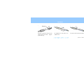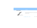
1
Air Motor
TRA-200
TRA-200-CP3
TRA-200-CP4
Operation Instructions
CONTENTS
Introduction ..........................................................................1
Parts Identification and Accessories ...............................10
Operation ............................................................................12
Connect Air Motor..........................................................12
Connect Attachment .......................................................15
Inspectiong and Sterilizing before Use ...........................17
Rotation Direction and Speed .........................................20
Disconnect Attachment...................................................22
Maintenance .......................................................................23
After Use.........................................................................23
Service ............................................................................... 32
Parts Replacement .......................................................... 32
Troubleshooting.............................................................. 40
Technical Information ........................................................ 43
Specifications ................................................................. 43
Terminology and Symbols ............................................. 47
Service and Other Contacts ............................................ 48
Disposal of Medical Devices.......................................... 48
Operation 2009-03-23
Introduction
1
Introduction
Thank you for purchasing a AIR TORX handpiece.
This instrument is designed for dental treatment such as grinding, drilling and polishing teeth.
For optimum safety and performance, read this manual thoroughly before using the unit and pay close attention to the
warnings and notes.
Keep this manual at hand for ready reference.
Caution: Federal law restricts this device to sale by or on the order of a dentist (for U.S.A.).
Safety Precautions
The instrument must be used in accordance with the instructions in this manual.
Read this manual thoroughly prior to operating or maintaining the instrument.
Operation 2009-03-23
2
Introduction
Note the meaning of these symbols:
WARNING : This warns the user of the possibility of extremely serious or irreversible injury or
a fatal accident.
NOTE
Usage Note
: This alerts the user to the risk of light to medium injury or equipment damage.
This alerts the user of important points concerning operation.
The user (i.e., clinic, hospital etc.) is responsible for the management, maintenance and use of medical devices.
This instrument must not be used by anyone except legally qualified dentists and oral surgeons / practitioners.
This instrument must not be used for any other than the intended purpose as specified in this manual.
Operation 2009-03-23
Introduction
3
Disclaimers
The J. Morita Mfg. Corp. will not be responsible for accidents, equipment damage, or bodily injury resulting from:
1. repairs made by personnel not authorized by the J. Morita Mfg. Corp.
2. any changes, modifications, or alterations of its products
3. the use of products or equipment made by other manufacturers, except for those procured by the J. Morita Mfg. Corp.
4. maintenance or repairs using parts or components other than those specified by the J. Morita Mfg. Corp. and other than in
their original condition
5. operating the equipment in ways other than the operating procedures described in this manual or resulting from the safety
precautions and warnings in this manual not being observed
6. workplace conditions and environment or installation conditions which do not conform to those stated in this manual such
as improper electrical power supply
7. fires, earthquakes, floods, lightning, natural disasters, or acts of God
Operation 2009-03-23
4
Introduction
The J. Morita Mfg. Corp. will supply replacement parts and be able to repair the product for a period of 10 years after the
manufacture of the product has been discontinued.
Warranty is honored only when a claim is accompanied by the warranty agreement with purchase date, product name and
model, serial number (inscribed on the body of the product) and name of the distributor.
* The user (i.e., clinic, hospital etc.) must perform the inspection procedures specified in the Regular Inspection Check List
every three months.
* Parts must be replaced periodically as necessary. The Regular Inspection Check List includes a replacement parts list.
* Attachments such as the straight handpiece, shank, and contra head have separate user manuals. Do not fail to read these
manuals before using the instruments.
Operation 2009-03-23
5
Introduction
PROHIBITION
Electromagnetic wave interference caused by cellular phones, transceivers, remote controls and similar
transmission devices could cause the equipment to operate in a random and possibly dangerous manner.
All devices which transmit electromagnetic waves near the treatment area should be turned off.
Operation 2009-03-23
Introduction
6
Medical Device Safety and Accident Prevention
Before using this equipment, carefully read the following:
1. Only fully trained and qualified personnel may operate equipment.
2. Items to be duly noted when installing equipment.
1) Locate the unit in a place where it will not get wet.
2) Install the unit in a location where it will not be damaged by air pressure, temperature, humidity, direct sunlight, dust,
salts, or sulfur compounds.
3) The unit should not be subjected to tilting, excessive vibrations, or shocks (including during shipping and handling).
4) Do not install the unit where chemicals are stored or where gas may be released.
3. Items to be duly noted before use.
1) Inspect all switch connections, polarity, dial settings, meters etc. to confirm that the equipment will operate properly.
Operation 2009-03-23
Introduction
7
2) Confirm that all cords are connected properly.
3) Take into consideration that simultaneous use of more than one instrument or device can create a dangerous situation or
lead to a mistake in diagnosis.
4) Reconfirm the safety of external circuits or systems which are connected directly to the patient.
4. Items to be duly noted during use.
1) Never use the equipment for treatment or diagnosis more than necessary or for longer than necessary.
2) Maintain a constant vigilance for abnormal conditions in both the equipment and the patient.
3) Appropriate steps, such as shutting the equipment down, should be devised to protect the safety of the patient in case
any abnormalities in the equipment or the patient are observed.
4) Make sure the patient does not handle or manipulate the equipment.
5. Items to be duly noted after use.
1) Turn the power off after returning dials, switches etc. back to their original positions in the prescribed order.
Operation 2009-03-23
Introduction
8
2) Do not use excessive force or pull the cord itself to disconnect cords.
3) The following items should be considered when storing the equipment:
(1) The storage area should protect the equipment from getting wet.
(2) The storage area should protect the equipment from any possible damage due to atmospheric pressure, temperature,
humidity, wind, direct sunlight, dust or air containing salts or sulfur.
(3) The equipment should be protected from tilting, vibrations, percussive shocks, etc. (including when it is being
moved).
(4) The storage are should be free of chemicals and gases.
4) All accessories, cords, etc. should be cleaned, properly arranged.
5) Before storage, the equipment should be cleaned so that it is ready for use again.
6. In case of a malfunction, the operator should attach a written notice indicating that the equipment is out of order without
attempting to repair the equipment himself; repairs should be referred to a qualified serviceman.
Operation 2009-03-23
Introduction
9
7. Equipment should not be modified in any way.
8. Maintenance and Inspection
1) All equipment and components should be inspected regularly.
2) Equipment which has not been used recently should always be inspected to confirm that it functions properly and safely
before being put back into use.
Operation 2009-03-23
10
Introduction
Parts Identification and Accessories
Parts Identification
O-rings
Frame
Speed Adjustment Ring
Connection Cylinder
Connection Buttons
Tube Connector
Operation 2009-03-23
11
Introduction
Accessories
Spray Nozzle
(Ethanol disinfectable)
AR Spray
(Ethanol disinfectable)
For TRA-200
For TRA-200-CP3
For TRA-200-CP4
*Standard Accessory
*AR Spray Can Accessory
*Standard Accessory
*Reuse the nozzle when you replace the AR spray can.
Operation 2009-03-23
12
Operation
Operation
Connect Air Motor
WARNING
• After connecting the motor, give it a light tug to make sure it is securely connected; otherwise, air pressure
might force it off the tube and result in an injury.
• Before connecting CP-3 and CP-4 models, check the lamp cover and o-ring on the tube. Make sure that the
lamp cover is securely tightend up and that the o-ring is not pushed back out of place; otherwise, air pressure
might force the instrument off its tube and result in an injury.
Operation 2009-03-23
Operation
13
Usage Note
• Handle the motor carefully. Do not drop it or bang it. This could impair its performance.
• Make sure the motor’s connection end and the o-rings on the main tube are clean and free of dust and debris.
Otherwise, the handpiece could malfunction.
Operation 2009-03-23
14
Operation
[TRA-200]
[TRA-200-CP3]
[TRA-200-CP4]
Tube Ring
Ring
Line up the pipes on the motor with
the holes in the tube connector, and
put the motor on the tube. Tighten
up the tube ring.
Hold the ring on the tube and push
the handpiece in until there is an
audible click.
Hold the tube and slide the handpiece
over until it clicks securely into place.
Operation 2009-03-23
15
Operation
Connect Attachment
WARNING
• Before use, check the motor and attachment carefully; give the attachment a light tug to make sure it is
securely connected. Otherwise, it might come off and injure the patient.
• Never put an attachment on or take one off while the air motor is actually running.
• For CP-3 and CP-4 models, the attachment could stick out of its holder somewhat depending on the
treatment unit. This creates a risk of accidental injury.
NOTE
• Do not change the rotation direction while the motor is actually running.
Operation 2009-03-23
Operation
16
Simple put the straight handpiece or shank attachment on the motor until
it clicks into place. The attachment is free turning.
Usage Note
• Attachments with lights cannot be used.
• If attachments are hard to put on and take off, apply a little AR Spray
to the o-rings on the connection cylinder.
Operation 2009-03-23
Operation
17
Inspectiong and Sterilizing before Use
The air motor is not autoclaved before shipping.
Do not fail to autoclave the motor before using it.
Initial Inspection
1. Make sure that no parts are loose and that the motor is not scratched or damaged.
2. Make sure the motor is securely connected to its tube.
3. Make sure that the cutting tool for the attachment is securely installed.
Operation 2009-03-23
Operation
18
4. Run the motor only at maximum speed without a load and check the following points.
* Do this with the spray turned off.
■ Runs smoothly and without any unusual noise.
■ Cooling air is coming out of the connection cylinder.
5. Run the motor only at maximum speed at maximum speed.
Connect an attachment and repeat the above test.
* Do this with the spray turned off.
See if it feels hot.
NOTE
Operation without cooling air can cause the attachment to heat up and result in a burn.
Operation 2009-03-23
19
Operation
6. Connect an attachment, run the motor at maximum speed without a load and check the following points.
■ Make sure the attachment is securely connected
■ Runs smoothly and without any unusual noise. A fine, misty spray is emitted.
■ There is not air or water leakage from the connection joints.
Operation 2009-03-23
Operation
20
Rotation Direction and Speed
WARNING
• Before actual use, always operate the handpiece outside the oral cavity to make sure it runs smoothly in the right
direction and at the right speed and that the burr does not wobble. Otherwise, the patient could be injured.
• Never touch the connection buttons while the Air Torx is actually running; this could cause it to come off and
injure the patient.
• Wait for the instrument to stop rotating before taking it out of the patient’s oral cavity; otherwise it could injure
the patient.
• For CP-3 and CP-4 models, take the attachment off when the air motor is not being used. Leaving it on
creates a risk of accidental injury.
Operation 2009-03-23
21
Operation
NOTE
Follow burr maker’s recommendation rotation speed and
direction.
Max.
Turn the Speed Adjustment ring to set the speed and rotation direction.
Speed Adjustment Ring
Forward
Usage Note
0
• Do not rotate the straight handpiece with its chuck open.
Reverse
Max.
Operation 2009-03-23
Operation
22
Disconnect Attachment
Press both connections buttons down all the way and then pull the
attachment off the motor.
Connection Buttons
Operation 2009-03-23
23
Maintenance
Maintenance
After Use
<Disconnect>
[TRA-200]
Take the motor off its tube.
[TRA-200-CP3]
[TRA-200-CP4]
Ring
Coupling
Hold the ring on the tube and pull
the handpiece straight off.
Pull the coupling slightly towards the
tube and then pull the handpiece off.
Operation 2009-03-23
24
Maintenance
<Cleaning>
Use the brush and running water to clean the air motor.
<Disinfection>
Use a piece of clean gauze and brush to disinfect the whole surface of air motor with Ethanol for Disinfection (Ethanol 80 vol%).
Usage Note
• Do not use anything other than ethanol.
• Do not use too much ethanol: it could seep inside and damage the motor.
• Do not wipe the o-rings on the connection cylinder with ethanol. This will remove their lubricant and result in
damaging them. Eventually this will lead to air and water leakage.
• Do not let debris get in the lines. This will cause poor rotation and spray delivery.
Operation 2009-03-23
25
Maintenance
<Lubrication>
[TRA-200]
Clean and lubricate the motor with AR Spray once a day or before
autoclaving. Take the motor off its tube. Set the speed adjustment
ring on the forward (F) side. Insert the AR Spray nozzle into the drive
air line, cover the exhaust line with a piece of gauze, and spray for 2 or 3
seconds.
Spray Nozzle
Air Exhaust (Spray exhaust)
Spray Nozzle
For TRA-200
Drive Air (Spray in here)
Operation 2009-03-23
26
Maintenance
[TRA-200-CP3, TRA-200-CP4]
Clean and lubricate the motor with AR Spray once a day or before
autoclaving. Take the motor off its tube. Set the speed adjustment ring
on the forward (F) side. Attach the spray nozzle to the spray can. Insert
the nozzle into the handpiece connection end and spray for 2 or 3 seconds.
Spray Nozzle
For TRA-200-CP3
For TRA-200-CP4
Operation 2009-03-23
Maintenance
27
WARNING
• Do not point the spray nozzle at anyone and do not use the spray near an open flame.
• For the TRA-200, spray will come out of the exhaust line; cover it with gauze before spraying. If spray
accidentally gets into your eyes, wash them out with plenty of water and see a doctor. Use soap and water to
wash off any spray on your skin.
Usage Note
•
•
•
•
•
The motor will malfunction without regular AR Spray maintenance.
Always use the AR Spray can in an upright position.
Shake the AR Spray can 2 or 3 times before using it.
The motor cannot be lubricated if the speed adjustment ring is set on zero.
Do not use any spray nozzle other than the one designed for the Air Torx motor.
Operation 2009-03-23
28
Maintenance
<Connect>
Connect motor to tube.
<Operate>
Run the motor for about 15 seconds to eliminate excess spray.
Operation 2009-03-23
Maintenance
29
<Disconnect>
Take the motor off its tube.
<Packaging>
Wipe the motor with a piece of gauze dampened with Ethanol for
Disinfection (Ethanol 80 vol%) and put it in a sterilization pouch.
Operation 2009-03-23
30
Maintenance
<Sterilization>
Recommended temperature and time: minimum of 5 minutes at 132° C in a sterilization pouch.
Minimum drying time after sterilization: 10 minutes.
WARNING
To prevent the spread of serious, life-threatening infections such as HIV and hepatitis B, the motor must be
autoclaved after the treatment of each patient.
NOTE
Instruments are extremely hot after autoclaving; do not touch them until they cool off.
Operation 2009-03-23
Maintenance
31
NOTE
•
•
•
•
Do not sterilize in any way except autoclave.
The handpiece could be damaged if it is not properly cleaned and lubricated before autoclaving.
Autoclave and drying temperatures must not exceed 135° C.
High autoclave temperatures can damage the o-rings etc. Put the motor in a sterilization pouch to keep it from
directly contacting heat sources or the inside of the autoclave.
• Do not leave the motor in the autoclave over night.
• Never wipe the motor with corrosive solutions such as electrolytic acid, strong alkaline solutions or other
commonly available cleaning solutions.
• Do not autoclave the motor with an attachment connected.
Operation 2009-03-23
32
Service
Service
Parts Replacement
■ Replace the parts listed in the Regular Inspection List (separate document) as necessary depending on degree of wear and
length of use.
■ Order replacement parts from your local dealer or the J. Morita Corp.
O-ring Set
One-way Valve (TRA-200 only)
Gasket (TRA-200 only)
Operation 2009-03-23
Service
33
<O-ring Replacement>
Connection Cylinder
The o-rings eventually wear out resulting in air or water leakage or both.
Replace all three o-rings at the same time.
WARNING
O-rings
Do not fail to take the old o-rings off. Leaving them on could
cause the motor to come off its tube and this could injure the
patient.
Operation 2009-03-23
Service
34
<One-way Valve Replacement (TRA-200 only)>
* If the one-way valve for the spray is defective, contamination could get in the water lines. Inspect this valve once a month.
Gasket
Spray Pipe
Usage Note
Pull
Returns: OK
Stops: No Good
Inspect the One-way Valve for the Spray
Use a disposable, plastic syringe with no needle. Slide the end of the
syringe over the spray pipe and press it flush up against the gasket. Pull
the plunger out slightly and see if it goes back towards the motor by
itself because of the partial vacuum created. If it doesn’t move back at
all, the one-way valve is defective and needs to be replaced.
• The motor will malfunction without regular AR Spray maintenance.
• Make sure the syringe fits tightly against the gasket without any gap whatsoever; otherwise, a vacuum will not be created inside
the syringe, and the plunger will not be pulled back even if the one-way valve is in good condition and working properly.
Operation 2009-03-23
Service
35
Replacement
Spray One-way Valve
* Use a needle or something to take the gasket off. Then take the
one-way valve out and replace it with a new one. Put the gasket back in
its original position.
Usage Note
Gasket
• The fat part of the spray pipe has a critical role in making a good seal; do
not scratch or damage it.
Operation 2009-03-23
Service
36
Storage
Ambient Storage conditions
Temperature -10 ~ 70 ºC
Humidity 10 ~ 85 % RH (without condensation)
Atmospheric pressure 700 ~ 1,060 hPa
* No frequent or continuous exposure to direct sunlight.
* If the motor will not be used for awhile, first autoclave it and then store it in a clean, dry place.
* The safe and effective working life of the motor is 7 years after manufacture provided it is properly inspected and maintained.
Operation 2009-03-23
Service
37
Inspection
Regular Inspection
* Use the Inspection Check List provided to inspect the instrument every 3 months.
* It is assumed that the user will perform regular maintenance and inspection procedures. However, if necessary or desired,
these may be performed by a trained professional qualified to repair medical devices. Contact your local dealer or the J.
Morita Office.
Operation 2009-03-23
38
Service
Regular Inspection Check List
Item
Attachment Connection
Procedure
Check that attachment can be securely connected to motor.
Operate the motor and make sure air pressure does not cause the attachment tocome off.
Repeat 3 times.
Air Motor Overheating
Run the motor without an attachment or load at maximum speed for 3 minutes.
Then see if it feels too hot.
Do the same thing with an attachment connected.
Motor Rotation Direction Control
Make sure the motor changes rotation direction properly.
Switch from forward to reverse rotation three times.
Operation 2009-03-23
39
Service
Item
Procedure
Run the motor at maximum speed by itself without a load and check the following.
1. Runs smoothly without unusual noise.
2. Cooling air is emitted from the connection cylinder.
Air Motor Rotation and Spray
Connect an attachment, run the motor at maximum speed and check the following.
1. Runs smoothly without unusual noise. Fine misty spray is emitted.
2. No air or water leakage at the motor’s joints.
3. Light works (if equipped with a light)
Operation 2009-03-23
40
Service
Repairs
* For repairs, contact your local dealer or the J. Morita Corp.
Troubleshooting
Use the check list below if the motor does not seem to be working properly.
* Contact your local dealer or the J. Morita Corp., if the apparatus does not work normally even after inspection,
adjustment or parts replacement, or if the dentist cannot perform maintenance procedures himself.
* Before inspection and adjustment, check to see if the main switch is on and if the main water and air valves are open.
Operation 2009-03-23
41
Service
Burr does not rotate
( Make sure the speed adjustment ring is not on “0.”)
Take the attachment off the motor.
Step on the pedal and see if the
motor runs
Doesn’t run
Lubricate with AR Spray.
Reconnect and make sure connection is securely tightened up.
Doesn’t run
Runs OK.
Runs OK.
Reconnect attachment and see if it works.
Doesn’t work
Have attachment inspected and repaired
See if air comes out of the main tube.
Yes
Have Air Torx inspected
and repaired
No
Have main tube and chair
inspected and repaired.
Operation 2009-03-23
42
Service
No spray from attachment
Take the attachment off the motor.
Step on the pedal and see if water comes out.
No
Disconnect motor.
Step on the pedal and see if water
comes out of the main tube.
No
Yes
Yes
Inspect connection cylinder o-rings.
Defective o-rings:
Replace all 3 o-rings.
(Coat o-rings with a little AR Spray.)
O-rings are OK:
Clean out the air and water nozzles
on the attachment.
(Refer to user’s manual for attachment.)
Still no water
Have main tube and chair
inspected and repaired.
Have Air Torx motor
inspected and repaired.
Have Attachment inspected
and repaired.
Operation 2009-03-23
Technical Information
43
Technical Information
Specifications
Model
Type
AIR TORX
TRA-200 / TRA-200-CP3 / TRA-200-CP4
Operation 2009-03-23
44
Technical Information
Air Pressure Range
Recommended Air Pressure Range
Water Pressure Range
Tip Air Pressure
Exhaust Pressures
Maximum Rotation Speed (At 0.25MPa)
Usage Speed Range (At 0.25MPa)
Stop Torque (At 0.25MPa)
Air Flow (At 0.25MPa)
0.2-0.3 MPa
0.25 MPa
0.05-0.2 MPa*with attachment
0.2-0.3 MPa *with attachment
Recommended: 0.07 MPa, max. *0.25 MPa (at output end)
20,000 ± 2,000 rpm
5,000-20,000 rpm
3.5 N・cm
46 NL/min
Operation 2009-03-23
45
Technical Information
Type
Dimension
Weight (Approx.)
Motor Length (Approx.)
Outer Diameter (Approx.)
Handpiece Coupling
Tube Connector
TRA-200
TRA-200-CP3
TRA-200-CP4
75 g
70 mm
φ20 mm
85 g
85 g
80 mm
85 mm
φ20 mm
φ20 mm
ISO3964: 1982 (only for attachments without lights)
ISO9168: 1991/
*SFSO-1, SFS-1, CP3-O
*CP4, CP4-O, CP4-WO, CP5-O
EN29168: 1994 Type C
* "SFSO-1,SFS-1" is Morita original connection tubing.
* "CP3-O" is Morita original coupling.
* "CP4, CP4-O, CP-WO, CP5-O" is Morita original coupling.
Operation 2009-03-23
46
Technical Information
* Ambient conditions for use
Temperature: 10~40° C.
Relative Humidity: 30~75 R% (without condensation).
Atmospheric pressure: 700~1,060 hPa.
NOTE
Excessive air pressure could impair the instrument’s performance. It could also result in an injury.
Usage Note
• Drive air should be clean and dry.
[Specifications may be changed without notice due to improvements.]
Operation 2009-03-23
47
Technical Information
Terminology and Symbols
CE (0197) marking
Model
Conforms to European medical device
Directive 93 / 42 / EEC.
Operation Instructions
Manufacturer
Type
Serial Number
Autoclavable up to 135° C
The first character of the serial number
specifies the year of manufacture as follows:
Authorized representative in
the European Community
X: 2009 Y: 2010 Z: 2011
Operation 2009-03-23
Technical Information
48
Service and Other Contacts
For repair or other types of service contact your local dealer or the J. Morita Office.
Disposal of Medical Devices
Any medical devices which could possibly be contaminated must be first decontaminated by the responsible doctor or
medical institution and then be disposed of by an agent licensed and qualified to handle medical and industrial waste.
Operation 2009-03-23
EU Authorized Representative under the European Directive 93/42/EEC
MEDICAL TECHNOLOGY PROMEDT CONSULTING GMBH
Altenhofstraße 80, 66386 St. Ingbert, Germany
TEL: +49-6894-581020 FAX: +49-6894-581021
The authority granted to the authorized representative, MEDICAL TECHNOLOGY PROMEDT Consulting GmbH,
by J. Morita Mfg. Corp. is solely limited to the work of the authorized representative with the requirements
of the European Directive 93/42/EEC for product registration and incident report.
J. MORITA MFG. CORP.
680 Higashihama Minami-cho, Fushimi-ku,
Kyoto, 612-8533 Japan
www.jmorita-mfg.com
Distributors
J. MORITA CORPORATION
Tokyo Office : 11-15, 2-Chome Ueno, Taito-ku,
Tokyo, 110-8513 Japan
Osaka Office : 33-18, 3-Chome Tarumi-cho, Suita,
Osaka, 564-8650 Japan
J. MORITA USA, Inc.
9 Mason, lrvine, CA 92618 U.S.A..
TEL:+1-949-581-9600, FAX: +1-949-465-1095
J. MORITA EUROPE GMBH
Justus-Von-Liebig-Strasse 27A, D-63128 Dietzenbach
Germany
TEL: +49-6074-836-0, FAX: +49-6074-836-299
SIAMDENT CO., LTD.
444 Olympia Thai Tower, 3rd Floor, Ratchadapisek Road,
Samsennok, Huay Kwang, Bangkok 10310, Thailand
TEL: +66-2-512-6049, FAX: +66-2-512-6099
J. MORITA CORPORATION Australia and New Zealand
Suite 2.05, Aero 247 Coward Street Mascot NSW 2020,
Australia
TEL: +61-2-9667-3555, FAX: +61-2-9667-3577
PUB. H5528-E Printed in Japan