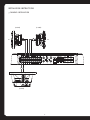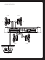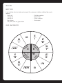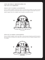
1
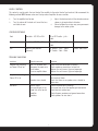
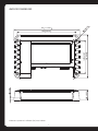
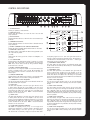
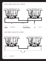
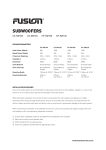
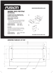
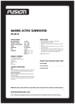
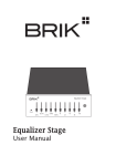
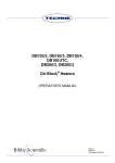
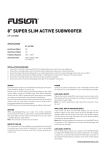
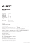
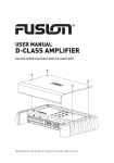
User / Installation Manual
D-Class Marine Amplifier
MS-DA51600
Specifications and design are subject to change without notice
AMPLIFIER SPECIFICATIONS
Peak Power (Watts)
1600
Frequency Response
10Hz -50kHz
Dimensions (mm)
300(l) x 210(w) x 50(h)
11-13/16 x 8-1/4 x 2”
80W RMS x 4 +
250W RMS x 1 @ 4Ω 1% THD+N
Power Ratings
130W RMS x 4 +
330W RMS x 1 @ 2Ω 1% THD+N
250W RMS x 2 @ 4Ω Bridged 1% THD+N +
250W RMS x 1 @ 4Ω 1% THD+N
INSTALLATION GUIDELINES
1.
2.
3.
4.
5.
Ensure the +12V lead is disconnected from the
battery before you connect any new equipment.
Ensure the mounting location will not interfere
with the gas tank or electrical wiring.
Ensure the Amplifier is securely fastened to the
vessel to prevent injury in the event of an accident.
Ensure all wiring is protected to avoid pinching
or crushing which could result in damage to the
audio system.
Ensure the mounting location has sufficient
6.
7.
air flow around the amplifier. If the amplifier is
mounted in an enclosed space a 3” fan with
ducting should be used to aid in air flow.
Do not mount any amplifier on a subwoofer
enclosure as extended exposure to vibration may
cause malfunction of the amplifier.
Ensure you use the recommended gauge wire/
cable for all amplifier connections.
+12V CONNECTION
WIRING
FUSION amplifiers should be connected directly to the
+12V battery terminal with an inline fuse or circuit
breaker as close the battery as possible.
Ensure the audio system is turned off before making any
connections to the amplifier, speakers or source unit,
failure to do so could result in permanent damage to the
audio system.
GROUND CONNECTION
When wiring the FUSION amplifier ensure that the cable
is protected from sharp objects and always use rubber
grommets when wiring through metal panels.
When grounding/earthing your amplifier ensure that the
location is a good source of ground. Make sure the metal
is clean of paint etc as a poor earth could damage your
audio system.
Ensure all terminals and connections are protected from
the vessel chassis and from each other as failure to do so
could result in permanent damage to the audio system.
REMOTE TURN-ON CONNECTION
This connection turns the amplifier on & should be
connected to the remote turn on wire from the Head
Unit. If one is not available a switched 12v source must
be used.
RCA INPUTS
Choose the correct length RCA cable & run them to the
RCA outputs of the source/head unit, avoiding running
beside other looms & or power cable.
2
LEVEL CONTROL
This control is used to match the input level of the amplifier to the output level of you head unit. We recommend the
following method. NOTE: Remove screws and the top cover of amplifier to access controls.
1.
Turn the amplifier level to zero
3.
2.
Turn the volume of the head unit to and the bass
and treble to zero
Adjust the level control until the desired maximum
volume is achieved without distortion.
4.
Failure to follow these steps may cause permanent
damage to the audio system.
CROSSOVER TABLE
Front
Selectable - LPF, HPF, or FULL
LPF or HPF Tunable - 32Hz 320Hz
Rear
Selectable - LPF, HPF, or FULL
LPF or HPF Tunable - 32Hz 320Hz
Sub
Fixed LPF and Fixed HPF
(Subsonic)
LPF Tunable - 32Hz - 320Hz
HPF Tunable - 10Hz - 80Hz
Tunable - 0dB-12dB
TROUBLE SHOOTING
Problem
Possible Reason
Solution
Amplifier not switching
on. Power LED not ‘on’.
No +12v to power wire
No power to remote wire
Fuse broken
Fuse on amplifier blown
Check fuses and connections to battery
Check remote on connections to head unit
Replace fuse with correct type and amperage
Replace fuse with correct type and amperage
Amplifier not working, but
Power LED is ‘on’
Amplifier too hot
Move amplifier to vented area
Turn head unit down
Check that there are no speaker wires shorted to
other wires
Speaker wires shorted
No Sound
No RCA Signal
Gain control not set up
Head Unit off or low vol
Amplifier
Speakers
Check RCA connection to head unit
Ensure you have set up the amplifier gain level control
Check head unit volume level
Check all power, remote on and ground connections
Check speakers for wire shorts
3
1/4
6.5
50 1-31/32"
12 15/32"
160 6-5/16"
210 8-9/32"
300 11-13/16"
268 10-9/16"
"
AMPLIFIER DIMENSIONS
All dimensions provided are in millimeters (mm) unless indicated
4
CONTROL DESCRIPTIONS
1
2
3
1. SPEAKER OUTPUT:
Connect your speakers to these terminals.
2. FRONT RCA INPUT:
Connect these RCA connectors to a head unit with a front low level
output connection.
3. REAR RCA INPUT:
Connect these RCA connectors to a head unit with a rear low level output
connection.
4. SUBWOOFER RCA INPUT:
Connect these RCA connectors to a head unit with a subwoofer low level
output connection.
5. REMOTE SUBWOOFER LEVEL CONTROL CONNECTION:
Connect the optional (supplied) Remote Level Controller to this socket.
6. POWER AND STATUS LED’S:
This displays “green” if the amplifier has been correctly powered up and
‘red’ if any faults are present.
7. FUSES:
Please ensure the correct type of fuse is fitted. For MS-DA51600 2 x
40A fuses.
8. +12V CONNECTION:
Connect directly to the vessel battery positive (+) terminal via a 4 gauge
power cable, with an inline fuse or circuit breaker at the battery end.
NOTE: This is the last wire to connect up during installation. Damage
could result if this is not done.
9. REMOTE TURN-ON CONNECTION:
This terminal is for turning the amplifier on & off. The remote input
requires a switched positive (+12V) to power ‘ON’ the amplifier. This
can usually be found on the rear of the head unit in the form of a
remote output.
10. GROUND CONNECTION:
Connect directly to the vessel’s earth system via a 4 guage power cable.
NOTE: This is the first wire to connect up during the installation.
11. SUBWOOFER LP FILTER FREQUENCY:
This sets the crossover frequency point for the subwoofer channels’ low
pass filter between 32Hz and 320Hz.
12. REAR LEVEL:
This allows level adjustment of the rear input signal. Use this control
to directly match the head unit to the amplifier. To set this control
correctly, turn the amplifier level to MIN and the head unit to 3/4 volume,
with the bass and treble on zero, then slowly turn up the level control
towards the MAX end of the control. NOTE: If the sound becomes
distorted, turn this control down.
13. FRONT LEVEL:
This allows level adjustment of the front input signal. Use this control
to directly match the head unit to the amplifier. To set this control
correctly, turn the amplifier level to MIN and the head unit to 3/4 volume,
with the bass and treble on zero, then slowly turn up the level control
towards the MAX end of the control. NOTE: If the sound becomes
distorted, turn this control down.
14. FUSION LOW FREQUENCY CONTROL:
The FUSION Low Frequency Control (F.L.F.C.) is a dual stage control
interface. The combination of a Subsonic filter & a Bass Boost control
allows precise shaping of the audio signal for your subwoofer(s).
The Subsonic filter is essentially a high-pass crossover which blocks
4
5
6
7
8
9
10
14
11
15
16
12
17
18
13
19
20
the frequency signal from 10Hz - 80Hz. This signal often contains no
music & its removal will improve subwoofer control. The Bass Boost is
a variable control to increase the level at 45Hz from 0 - +12dB of gain.
Adjust these controls with extreme care.
15. SUBWOOFER AUDIO SOURCE:
This switch selects the audio source for the subwoofer channel. Audio
can be sourced from the SUB input RCA connectors or from the FRONT &
REAR input RCA connectors.
16. SUBWOOFER LEVEL:
This allows level adjustment of the subwoofer input signal. Use this
control to directly match the head unit to the amplifier. To set this
control correctly, turn the amplifier level to MIN & the head unit to 3/4
volume, with the bass and treble on zero, then slowly turn up the level
control towards the MAX end of the control. NOTE: If the sound becomes
distorted, turn this control down.
17. REAR FILTER FREQUENCY:
This sets the crossover frequency point for the rear filter between
32Hz and 320Hz. NOTE: Failure to correctly set could result in speaker
damage.
18. REAR FILTER SELECTION:
This switch selects the type of filter used for the rear audio signal.
Either Low Pass, High Pass or Full Range can be selected. The Low Pass
filter is designed to filter out all mid to high frequencies that only full
range speakers should produce. The High Pass filter is designed to filter
out all low frequencies that only subwoofers should produce. Full Range
allows all frquencies.
19. FRONT FILTER SELECTION:
This switch selects the type of filter used for the front audio signal.
Either Low Pass, High Pass or Full Range can be selected. The Low Pass
filter is designed to filter out all mid to high frequencies that only full
range speakers should produce. The High Pass filter is designed to filter
out all low frequencies that only subwoofers should produce. Full Range
allows all frquencies.
20. FRONT FILTER FREQUENCY:
This sets the crossover frequency point for the front filter between
32Hz and 320Hz. NOTE: Failure to correctly set could result in speaker
damage.
5
INSTALLATION INSTRUCTIONS
3 CHANNEL INSTALLATION
(2-8 Ohm)
(2-8 Ohm)
RL
RR
(2-8 Ohm)
6
5 CHANNEL INSTALLATION
(2-8 Ohm)
(2-8 Ohm)
RL
RR
FR
FL
(2-8 Ohm)
(2-8 Ohm)
(2-8 Ohm)
7
TECH TIPS
BASIC TOOLS
In any installation these basic tools may be required. For custom type installations, additional tools may be
neccesary.
•
•
•
•
•
Electric drill
Crimping tool
Allen key set
Wire strippers
Utility knife, sabre saw, jigsaw, nibbler
•
•
•
•
Flat blade screwdriver
Electrical tape
Phillips screwdriver
Silicon sealant
OHMS LAW SIMPLIFIED
E
I
IR
E
ce
an
st
si
re
vo
lta
WR
I
W
E2
R
R
W
E
w
at
ts
ge
ra t
pe ren
am cur
E
R
E2
W
W
I2
ge
W
I
I 2R
W/R
EI
8
SERIES AND PARALLEL SUBWOOFER WIRING FOR
DUAL VOICE COIL SUBWOOFERS
PARALLEL VOICE COIL WIRING (2 OHM OPERATION)
To wire a 4 Ohm DVC subwoofer in parallel to get 2 Ohm, use two short pieces of speaker wire and link the positive
from one coil to the positive of the second coil, and do the same for the negative as shown below. Then wire the
amplifier to opposite sides of the subwoofer in order to equalise any connection resistance.
-
+
2 Ohm operation
SERIES VOICE COIL WIRING (4 OHM OPERATION)
To wire a 4 Ohm DVC subwoofer in series to get 8 Ohms, use one short piece of speaker wire and link the positive
from one voice coil to the negative of the second coil as shown below. Then wire the amplifier to opposite sides of
the subwoofer.
-
+
8 Ohm operation
9
PARALLEL WIRING FORMULA FOR 2 SPEAKERS
4 Ohm
8 Ohm
2.67 Ohms
R1 x R2
=
R1 + R2
LOAD IMPEDANCE
4 Ohms x 8 Ohms
4 Ohms + 8 Ohms
=
32
12
SERIES WIRING FORMULA FOR 2 SPEAKERS
4 Ohm
4 Ohm
8 Ohms
R1 + R2
=
LOAD IMPEDANCE
10
=
2.67 Ohms
RECORD YOUR PURCHASE DETAILS HERE:
SERIAL NUMBER
DATE OF PURCHASE
AFFIX RECEIPT HERE
www.fusionelectronics.com
FUSION Electronics New Zealand
FUSION Electronics Australia
FUSION Electronics Europe
FUSION Electronics USA
Ph: +64 9 369 2900
Ph: +61 1300 736 012
Ph: +44 845 299 7586
Ph: +1 623 580 9000
For further product and installation information, please visit www.fusionelectronics.com
Pour plus d’informations sur les produits et l’installation, rendez-vous sur www.fusionelectronics.com
Para obtener más información acerca de los productos y de su instalación, visite el sitio web www.fusionelectronics.com
Bezoek www.fusionelectronics.com voor meer product- en installatie-informatie.
Weitere Produkt- und Installationsinformationen finden Sie unter www.fusionelectronics.com
Per ulteriori informazioni sui prodotti e la loro installazione, potete visitare www.fusionelectronics.com
Для получения дополнительной информации о продуктах и установке зайдите, пожалуйста, на: www.fusionelectronics.com
WARNING: Audio Systems can produce sound levels over 135dB. Continuous exposure to sound pressure levels over 100dB may cause permanent hearing loss! Please watch for emergency
vessels as warning signals may not be heard. USE COMMON SENSE!
PUBLISHED BY FUSION ELECTRONICS LIMITED: © Copyright 2010 by FUSION Electronics Limited. All rights reserved. Specifications and design are subject to change without notice.
YOU CAN HELP PROTECT THE ENVIRONMENT! Please remember to respect the local regulations: Hand in the non-working electrical equipment to an appropriate waste disposal center.
11