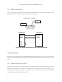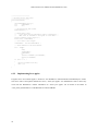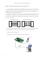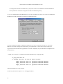
1
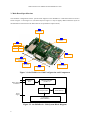
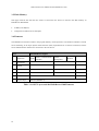
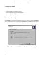
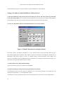
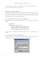
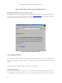
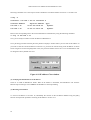
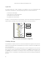
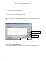
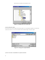
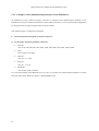
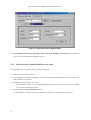
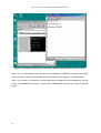
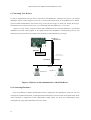
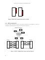
Starter Kit and User Manual for the
HelloDevice 1300
Version 1.1
Starter Kit and User Manual for the HelloDevice 1300
Version 1.0
Last revised on July 16, 2000-07-16
Printed in Korea
Copyright
Copyright 2000, Sena Technologies, Inc. All rights reserved.
Sena Technologies reserves the right to make changes and improvements to its product without providing notice.
Trademark
HelloDevice™ is a trademark of Sena Technologies, Inc.
Windows® is a registered trademark of Microsoft Corporation.
Ethernet® is a registered trademark of XEROX Corporation.
Notice to Users
When a system failure may cause serious consequences, protecting life and property against such consequences
with a backup system or safety device is essential. The user agrees that protection against consequences resulting
from system failure is the user's responsibility.
This device is not approved for life-support or medical systems.
Changes or modifications to this device not explicitly approved by Sena Technologies will void the user's
authority to operate this device.
Company Address
Sena Technologies, Inc.
210 Yangjae-dong, Seocho-gu
Seoul, Korea 137-130
Telephone: +82-2-573-7772
Fax: +82-2-573-7710
Email: [email protected]
Website: http://www.sena.com
Table of Contents
1. Before You Start
2. Overview
3. Main Board Specifications
3.1. Power Supply
3.2. Microprocessor
3.3. Ethernet Interface
3.4. Serial Communication Interface
3.5. Flash Memory
3.6. Firmware
4. Setting Up the Hardware
4.1. Installing Utility Software
4.2. Connecting Hardware
4.3. Configuring Network
5. Quick Tour
5.1. Building a Homepage
5.2. Serial Communication Demo Using Terminal Applet
6. Connecting User Devices
6.1. Connecting Hardware
6.2. Sample programs
Appendix A. IP address configuration by using cross-over Ethernet cable
Starter Kit and User Manual for the HelloDevice 1300
1. Before You Start.
§
Items supplied in the HelloDevice 1300 Starter Kit
Items
Piece(s)
Hardware
Software
HelloDevice 1300 Main Board
1
5V Switching Mode Power Supply (SMPS) or Power Adaptor
1
DSUB Cable for RS232 Communication
1
HelloDevice Utility Software and Sample Demo Program
1
(Download the latest version at http://www.sena.com/download)
User’s Manual
§
§
Operating Environment
−
Voltage Supply = 5V DC ±10%
−
Current Supply = 200mA or lower
−
Operating Humidity = 0 ~ 95%
−
Operating Temperature = 0 ~ 50 Degrees Centigrade
Technical Support
Sena Technologies, Inc.
210 Yangjae-dong, Seocho-gu, Seoul, Korea 137-130
Phone: (+82-2) 573-7772
Fax: (+82-2) 573-7710
Email: [email protected]
http://www.sena.com
4
1
Starter Kit and User Manual for the HelloDevice 1300
2. Overview
The HelloDevice is a connectivity solution that allows any device in any industry to communicate over any
network, using any interface. The HelloDevice 1x00 product family is a board-level Ethernet controller that lets
manufacturers and system integrators connect devices such as home appliances and industrial control systems
directly to the Internet via Ethernet, and remotely communicate with and control them with standard web
browsers such as Microsoft Explore and Netscape Navigator. The HelloDevice 1x00 product family is
categorized into three types depending on how the HelloDevice connects to a user device:
§
Digital I/O communication module (HelloDevice 1100)
§
Dual-port RAM communication module (HelloDevice 1200)
§
Serial communication module (HelloDevice 1300)
Table 2.1 shows the basic specifications of the HelloDevice 1x00 Series.
Model
Basic Spec.
HelloDevice 1100
HelloDevice 1200
HelloDevice 1300
Scenix Sx52BD
(8 bits microprocessor, 50 MIPS)
512 Kb flash memory
(Saves user Web files)
CPU
Memory
Network
Connection
10 Base-T Ethernet Interface (IEEE802.3)
Connection to the
User device
Internet Protocol
Support
Utility Software
16 contact points digital
1 channel
input
2 KB dual port RAM
RS-232/485
16 contact points digital
Max. 38,400 bps
output
HTTP1 / SMTP / BOOTP
TCP / UDP
IP / ICMP / ARP
Ethernet (IEEE802.3)
HelloDevice utility software (for Windows 95/98/NT/2000 platform)
: IP addressing and Web page uploading
Table 2.1 Basic specifications of the HelloDevice 1x00
1
5
Currently, HTTP 1.1 specifications are supported.
Starter Kit and User Manual for the HelloDevice 1300
3. Main Board Specifications
The hardware configuration and the system block diagram of the HelloDevice 1300 Main Board are shown
below in Figure 3.1 and Figure 3.2. (The board layout in Figure 3.1 may be slightly different from the layout of
the HelloDevice main board in the Starter Kit for the performance improvement.)
5
512 KB
Flash Memory
3-1
10BaseT Ethernet
controller
3-3
Status LED's
Power
Collision
Rx
Tx
2
microprocessor
3-2
53 mm
RJ-45
Ethernet Connector
86 mm
To Ethernet
4-2
Serial Port
(RS-232/485)
4-1
1
Power Supply
( 5V DC )
RS-232/485
Conversion switch
Figure 3.1. the HelloDevice 1300 Configuration and Components
RJ45 connector
to Ethernet
10 Base-T
filter
Ethernet controller
(10 Base-T)
Sx52BD
microprocessor
512 KB
Flash Memory
Power
supply
1 serial port
(RS232/RS485)
Figure 3.2. the HelloDevice 1300 System Block Diagram
6
Starter Kit and User Manual for the HelloDevice 1300
3.1 Power Supply
§
§
Voltage supply = 5V DC ±10%
Current supply = 200mA or lower
3.2 Microprocessor Specifications
§
Scenix SX52BD 8 Bit Microprocessor
§
4 KByte Program Memory
§
52-pin PQFP (See Figure 3.1, Part [2])
3.3 Ethernet Interface
The HelloDevice is connected to an Ethernet hub or switch by the RJ45 connector on the Main Board. Distances
of up to 100m are supported.
3.3.1 Ethernet Controller
The Ethernet Controller provides the functions of framing and addressing data, and detecting and avoiding errors
and collisions (See Figure 3.1, Part [3-1]).
3.3.2 Specifications
§
RealTek Full-duplex Ethernet Controller: RTL8019AS
§
Supports 10 base-5, 10 base-2 and 10 base-T compliant with IEEE802.3
§
16 KByte SRAM
§
NE2000 Compatible
3.3.3 RJ45 Connector
§
7
Shielded Connector compliant with AT&T258 specifications (See Figure 3.1, Part [3-2])
Starter Kit and User Manual for the HelloDevice 1300
1=Tx+
8=NC
2=Tx-
7=NC
3=Rx+
4=NC
6=Rx -
Pin No.
Description
Red Line
1
Tx+
White with orange
2
Tx-
Orange
3
Rx+
White with green
4
Not used
Blue
5
Not used
White with blue
6
Rx-
Green
7
Not used
White with brown
8
Not used
Brown
5=NC
Figure 3.3. RJ45 connector
3.3.4 Status Indicator LED's
There are four status indicator LED’s which indicate the following: (See Figure 3.1, Part [3-3]).
§
Power LED
Indicates the Power-On status of the HelloDevice.
§
Rx LED
Indicates that the Ethernet controller is receiving Ethernet packets from the network. If it is correctly
connected to the network, this LED will blink when packets are received
§
Tx LED
Indicates that the Ethernet controller is sending packets.
Before setting the HelloDevice network
configuration, this LED will blink every second. After network configuration, if connected correctly, this
LED blinks only in response to requests from the user's PC, for example ping or server activity.
§
Collision LED
Indicates that one or more Ethernet packets transmitted from the Ethernet controller to the network may
have collided with another packets. In this case, the Ethernet controller will automatically resend the packets.
8
Starter Kit and User Manual for the HelloDevice 1300
3.4 Serial Communication Interface
§
RS232/485 communication mode switching by sliding switch
§
DB9 connector for RS232/RS485 communication
§
150 ~ 38400 baud rate
Pin assignment of 9-pin DSUB connector is shown in Figure 3.4. All the signal lines for RS232 and RS485
communication are included in the HelloDevice serial port. Communication mode is switched by using
RS232/485 conversion switch, which is represented as SW2 in the main board.
3=TxD
2=RxD
1=RS485+
6=DSR
7=RTS
Pin No.
1
2
3
4
5
6
7
Symbol
RS485+
RxD
TxD
RS485GND
NC
RTS
Description
RX485+
Receive Data
Send Data
RX485Signal Ground
Not connected
Ready To Send
8
9
CTS
NC
Clear To Send
Not connected
4=RS485-
5=GND
9=NC
8=CTS
Function
485 data line
Data Input
Data Output
485 data line
Handshake Output
(+12V=Ready to Rx, -12V=Not Ready to Rx)
Data sent
Data sent only at +3V ~ 12V
Figure 3.4. Pin Assignment of the HelloDevice DSUB Connector
9
Starter Kit and User Manual for the HelloDevice 1300
3.5 Flash Memory
Web page resources files that the user creates to control the user device are stored in the flash memory of
HelloDevice Main Board.
§
4 MBits (512 KBytes)
§
Composed of 2,048 sectors of 256 Bytes.
3.6 Firmware
The HelloDevice Firmware resides in the program memory of microprocessor. The firmware includes a TCP/IP
stack conforming to the Open System Interconnection (OSI) requirements for an Internet connection, and the
serial communications interface for connection to the user device.
Layer
The HelloDevice Support
HTTP
Serial Communication. System
Interface
Management
7
Application
6
Presentation
5
Session
4
Transport
3
Network
TCP
2
Data link
IP / ICMP
1
Physical layer
Ethernet (IEEE802.3)
BOOTP
UDP
Table 3.1. OSI 7 Layers and the HelloDevice 1300 Firmware
10
ARP
Starter Kit and User Manual for the HelloDevice 1300
4. Setting Up the Hardware
The HelloDevice 1300 is as follows:
§
Install the HelloDevice Utility Software on user's PC
§
Connect the HelloDevice to the power supply and Ethernet
§
Set the IP address of HelloDevice
§
Check the HelloDevice network connection.
4.1 Installing Utility Software
Run setup1x00.exe in the HelloDevice CD-ROM from the PC that is connect to the network. Setup1x00.exe
runs on Microsoft Windows 95/98, NT and 2000. Select [Complete] and press [Next] button in the setup type
display screen.
Figure 4.1. Initial screen of the HelloDevice utility software installation program
11
Starter Kit and User Manual for the HelloDevice 1300
The setup program will automatically be installed onto c:\Program Files\HelloDevice utility folder.
Figure 4.2. Screen that shows the HelloDevice utility software is being installed
Once setup is completed, a shortcut icon of the HelloDevice Utility Software is created on the desktop and on the
program menu. If the following HelloDevice utility main window appears when the shortcut is clicked, the setup
has been successfully completed.
Figure 4.3. Initial screen for the HelloDevice utility software
12
Starter Kit and User Manual for the HelloDevice 1300
4.2 Connecting Hardware
(1) Connect the 5V power supply adaptor to the HelloDevice.
110/220 V
5V Power
HelloDevice
Figure 4.4. 5V power connection to the HelloDevice
(2) Connect the HelloDevice to the Ethernet hub through the RJ45 connector.
(Refer to the Chapter 3 Main Board Specifications for more details on the RJ45 connector.)
Ethernet backbone
110/220 V
5V Power
HelloDevice
Ethernet Cable
Hub or Switch
Figure 4.5. Connection of the HelloDevice and Ethernet cable
(3) Check to see if the Tx LED of the HelloDevice Status Display LED blinks periodically in one-second
interval. (See the [Status LED] in the Figure 3.1)
13
Starter Kit and User Manual for the HelloDevice 1300
4.3 Configuring Network
In order for a HelloDevice to function as a server on the network, a static IP address must be set for the
HelloDevice. This section describes how to configure and change IP address for a HelloDevice.
4.3.1 Setting IP Address
The HelloDevice Utility Software is used to set up an IP address for a HelloDevice by utilizing BOOTP
(BOOTstrap Protocol), which is defined in the Internet protocol standard, RFC-951 and RFC-1542. The Utility
Software provides BOOTP a server function, and will respond to the BOOTP request of the HelloDevice.
Since the factory default setting of the HelloDevice IP address is 0.0.0.0, the HelloDevice sends BOOTP request
for IP assignment, when it is powered up for the first time. Thus, users can see Tx LED keeps blinking
periodically as a reminder (See Figure 3.1, Status LED).
Since IP address of the HelloDevice is managed by an IP address database, a properly allocated MAC2-IP
address record should be entered into the database. For a valid IP address, users should ask their network
administrator.
BOOTP database record
management function
BOOTP database list
BOOTP server function
IP address tracing/modifying function
Figure 4.6 IP address setting screen of the HelloDevice utility software
2
MAC(Media Access Control) address is total 6 bytes and it is composed of 3 bytes-organization code and 3
bytes-product code. MAC address of HelloDevice is composed of 00-01-95 which is a company code and xx-xxxx which is a product code. E.g. 00-01-95-01-aa-08
14
Starter Kit and User Manual for the HelloDevice 1300
Take the following steps to set up the IP address, using the HelloDevice Utility Software.
Setting an IP address with the HelloDevice Utility Software:
(1) Run the HelloDevice Utility shortcut icon on the desktop of your PC and select [IP Set-up] menu click
on the [IP Set-up] window. This window provides the BOOTP server function for IP address setup (([BootP
Start], [BootP Stop]), trace function ([IP Find]) and IP address initialize functions ([IP Clear]).
(2) Press the [Add] button and enter the BOOTP database record as shown below.
Figure 4.7 BOOTP Database Record Input Window
Enter MAC address, IP address of HelloDevice. 1 and 6 should be always entered for H/W address type and
H/W address length items for Ethernet. MAC address is printed on the sticker on the Ethernet controller chip of
HelloDevice main board. Figure 4.7 shows an example setting of 00:01:95:04:02:03 MAC address and
192.168.1.15 IP address. Since the BOOTP function of HelloDevice is working by using broadcast message, you
don’t have to enter gateway address and sub net mask.
(3) Click [Add] button to finish database editing.
The records entered in step (2) are added to the IP database.
(4) Launch the functions of BOOTP by pressing the [BootP start] button.
The HelloDevice Utility will then operate as a BOOTP server. Note that the message on the [Status] bar will
change from “Monitoring” to “Listening BOOTP request”.
If HelloDevice Utility gets BOOTP request from a certain HelloDevice which does not exist in BOOTP DB
15
Starter Kit and User Manual for the HelloDevice 1300
List, it will run "DB Setting for BOOTP" window automatically. User should enter IP address and Gateway
address of the HelloDevice, and add them to BOOTP DB list.
(5) Check the status of Tx LED on HelloDevice.
The HelloDevice Utility Software will send a reply for IP assignment to the BOOTP request of the HelloDevice.
The Tx LED will be blinking periodically to indicate a BOOTP request. At this point, [Status] bar displays the
“BootP reply sent... [ 192.168. 1. 15 ]” message. Wait until Tx LED does not blink any longer, and then stop
the functions of BOOTP server by clicking [BOOTP Stop] button.
(6) Use the ping command to check your IP address setting of HelloDevice.
Run the ping program at the command prompt. If your IP address is correctly set, the response to the ping will be
as follows:
>> ping 192.168.1.15
>> Pinging 192.168.1.15 with 32 bytes of data:
Reply from 192.168.1.15: bytes=32 time=10ms TTL=251
Reply from 192.168.1.15: bytes=32 time<10ms TTL=251
Reply from 192.168.1.15: bytes=32 time=10ms TTL=251
If the response above is not displayed, the IP address was not entered correctly, so you should repeat steps (4),
(5) and (6).
(7) Use [IP Find] to identify IP address setting of HelloDevice.
Click [IP Find] button, and the window in figure 4.8 will be shown. Enter the MAC address of HelloDevice and
click [Find] button. The IP address currently set in the “Found IP” item will be displayed.
16
Starter Kit and User Manual for the HelloDevice 1300
Figure 4.8 IP address check using the [IP Find] function
(8) Check if the HelloDevice web server operates correctly.
The HelloDevice has a built-in 404.html file in flash memory (factory default). To check the functions of your
web server, run any web browser and connect to the address http://192.168.1.15. The web page in Figure 4.9
verifies that the HelloDevice works successfully as a web server.
Figure 4.9 HelloDevice default Web page
4.3.2 Changing IP address
To change the IP address, initialize the IP address to the factory default value of 0.0.0.0, and repeat the
procedures of setting an IP address in section 4.3.1. At this point, ask your network administrator for a new IP
address.
For example, let's try to change IP address of 192.168.1.15 to 192.168.1.18.
(1) Initializing IP address
Before you initialize IP address of HelloDevice, you have to remove IP/MAC address data stored in your PC.
This information is stored in ARP cache, and you can make sure what is stored in the cache by using the
17
Starter Kit and User Manual for the HelloDevice 1300
following command. This is the response of the command in case that IP address of user PC is 192.168.1.100.
>>arp -a
Interface: 192.168.1.100 on Interface 2
Internet Address
Physical Address
Type
192.168.1.15
00-01-95-04-02-03
dynamic
192.168.1.23
01-a0-11-34-11-0d
dynamic
Remove the corresponding item to the current HelloDevice information by using the following command.
>> arp –d 192.168.1.15
Now, you are ready to initialize current IP address of HelloDevice.
Go to [IP Setup] window and click [IP Clear] button to display a window where you can clear the IP address. If
you want to clear the current IP address of 192.168.1.15, just enter the current setting of the IP address as shown
below in figure 4.10 and click [OK] button. Then, the present IP address of 192.168.1.15 set on HelloDevice will
be changed to factory default of 0.0.0.0.
Figure 4.10 IP address Clear window
(2) Verifying the initialization of an IP address
Check if Tx LED of HelloDevice blinks. When an IP address is initialized, the HelloDevice will send the
BOOTP request message. The Tx LED of the HelloDevice will keep blinking.
(3) Resetting an IP address
To reset an IP address to 192.168.1.18, edit/modify the contents of the IP address database using the [Edit]
function and repeat the procedures of setting an IP address in section 4.3.1.
18
Starter Kit and User Manual for the HelloDevice 1300
Figure 4.11 IP address change using the [Edit] function in the IP address database
19
Starter Kit and User Manual for the HelloDevice 1300
5. Quick Tour
This chapter describes how to build a homepage on the HelloDevice web server and demonstrates serial
communication of the HelloDevice. The following sample program files are included in the Starter Kit.
1) First Web server demo sample
2) Demo sample of I/O control through the Web
3) Java applet source code for I/O demo
4) C program source code for I/O demo
In chapter 5.1, we will start the Web server using the sample 1), and test serial communications through the Web
using the sample 2). The sample 3) and 4) will be covered in Chapter 6, Connecting User Devices.
Sample (1)
Sample (2)
Sample (4)
Sample (3)
Figure 5.1 Location of the HelloDevice Sample Files
5.1 Building a Homepage
For the HelloDevice to function as a web server, web resources like HTML files, image files, and Java class files
should be stored on the flash memory of the HelloDevice up to 256 files or a total data size of 500 KByte can be
stored on the flash memory.
Since the HelloDevice does not use a general operating ststems, web files are managed in the form of “file index
table”. Web files are stored in the flash memory of the HelloDevice by building an integrated image file and
then uploading it onto the HelloDevice. This image file contains a file index table that is recognized only by
HelloDevice web server. The HelloDevice Utility Software provides the functions of building and uploading this
type of file.
20
Starter Kit and User Manual for the HelloDevice 1300
To make HelloDevice function as a web server, perform the following steps:
(1) Create the web pages with a web-publishing tool.
(2) Use the HelloDevice Utility Software to transform the created web pages into an uploadable form.
(3) Upload the transformed files to the HelloDevice.
(4) Use a web browser to connect to the uploaded web page.
In this example, use the web files in the “FirstDemo” folder to construct a web server home page. These
examples are composed of: an index.html, HelloDevice block diagram and cube animation demo with a Java
applet.
(1) Select [Web files] tab to go to the window containing web file manager tools.
Find and Build Web File
List box clear
Select Build File
Upload Built File
Figure 5.2. Web File Tool screen of the HelloDevice Utility Software
(2) Click [Find] button to find web files to build.
Go to the folder containing the example files, select the top-level “FirstDemo” folder, and click [OK] button.
21
Starter Kit and User Manual for the HelloDevice 1300
Figure 5.3. Finding Web server demo files
(3) Select a file name to build.
Enter the file name of the built image and click [Save] button to save. By default the HelloDevice web files built,
will have the extension “hd”. The current window closes and “Build complete” dialog box appears.
Figure 5.4. Saving Web sample Build file
(4) Enter an IP address of the HelloDevice to upload the built files.
22
Starter Kit and User Manual for the HelloDevice 1300
Figure 5.5. Entering the IP address to upload the built files
(5) Click the [Target file] button to select the built image files to upload.
Figure 5.6. Screen of selecting the Build files to upload
(6) Click [Upload] button to upload the built image files to HelloDevice.
This procedure is displayed on the Progress bar, and when it has finished, a “Flash download completed!!”
dialog box will appear.
23
Starter Kit and User Manual for the HelloDevice 1300
(7) Enter URL http://192.168.1.15/index.html in the web browser, and try connecting.
The web page in Figure 5.7 will appear. If not, you might not have entered the value of the IP address correctly
and as a result the web server will not operate successfully. If the web page fails to appear, check the IP
address setting of web server and reload the file.
Figure 5.7. HelloDevice, “FirstDemo” Web page screen
A user's homepage can be customized in the same way as described above.
24
Starter Kit and User Manual for the HelloDevice 1300
5.2 Serial Communication Demo Using Terminal Applet
Sample programs are provided in the HelloDevice 1300 Starter's Kit, for serial communication demo. Let’s
check the function by using one of the sample programs. You will need a PC equipped with Ethernet card and
serial port for Ethernet-to-RS232 data conversion demo.
The scenario is as follows: If you connect to the homepage of the HelloDevice by using any browser, a terminal
applet page will be shown to you. If you enter any character by pressing any key on keyboard, the characters will
be transferred to the HelloDevice over network. Then, the characters will be transferred to user PC by way of the
HelloDevice RS-232 port, if the HelloDevice is hooked up with serial port of user PC. You can see the data
stream on your PC by using any RS232 terminal emulator. You may send characters to the network interface of
your PC by entering any characters on your RS232 emulator. Take following steps for this demo.
§
Configure serial communication parameter of the HelloDevice
§
Hook up your PC and the HelloDevice for demo
§
Building a Homepage for demo
§
Test RS232 communication demo
Conceptual drawing for this demo system is shown in Figure 5.8.
Ethernet backbone
TCP/IP communication
Terminal Applet (Socket Interface)
HelloDevice
192.168.1.15
192.168.1.14
TCP port 6001
RS232 terminal
(COM1 or COM2)
RS232 communication
Figure 5.8 Conceptual drawing for the serial communication demo
25
Starter Kit and User Manual for the HelloDevice 1300
5.2.1. Configure serial communication parameter of the HelloDevice
the HelloDevice Utility software provides a function to configure serial communication parameter of the
HelloDevice serial port to make the parameter as same as that of user device. You can perform this configuration
by using the function of [Sys Set-up] window of Utility software.
Take following steps to configure the parameters.
1) Select [Serial] item from [Device] selection combo box.
2) Set the proper item from parameter combo box.
§
baud rate
One of 150, 300, 600, 900, 1200, 2000, 2400, 3600, 4800, 7200, 9600, 19200, 38400
§
parity
One of None, Even, Odd
§
Data bits
One of 5, 6, 7, 8 bits
§
Stop bits
One of 1, 1 ½, 2 bit
§
handshake
One of None, H/W, X On/Off
Let’s say that IP address of the HelloDevice is 192.168.1.15, and the serial communication parameters are 9600
baud rate, Parity None, Data bit 8, Stop bit 1 and Handshake None.
26
Starter Kit and User Manual for the HelloDevice 1300
Figure 5.9 Serial parameter input window
3) Press [Send] button and these parameters will be sent to the HelloDevice via network. the HelloDevice
will set its serial communication parameter as such.
5.2.2 Hook up your PC and the HelloDevice for demo
Take following steps to properly hook up the demo components.
1) Prepare a PC connected to network.
2) Hook up RS232 cable between the RS232 port of your PC and that of the HelloDevice. You can refer to the
cable specification at chapter 3.
3) Run RS232 terminal emulator on your PC.
We will show this demo by using HyperTerminal program of your PC. Let’s say you are using COM1
port for serial communication demo.
4) Set the parameters of HyperTerminal program.
Set the parameters as same as those of the HelloDevice serial port, as you finished in chapter 5.2.1.
27
Starter Kit and User Manual for the HelloDevice 1300
Figure 5.10 RS232 parameter of HyperTerminal
5) Run HyperTerminal by press [OK] button.
5.2.3 Building a Homepage for Demo
Use sample web files of the HelloDevice Utility Software in “Demo\SerialDemo” folder to test RS232
communication of the HelloDevice (See Figure 5.1 for the location of the sample files). index.html, terminal.jar
and 404.html files in the folder are used.
(1) Modify index.html file in “SerialDemo” folder.
Enter IP address of the HelloDevice currently in the IP address parameter associated with Java applet within
index.html file. Save the file without modifying other parameters.
28
Starter Kit and User Manual for the HelloDevice 1300
<HTML>
<HEAD>
<TITLE>telnet</TITLE>
</HEAD>
<BODY>
<H1>telnet</H1>
<APPLET CODE=telnet.class ARCHIVE=serial.jar WIDTH=590 HEIGHT=190>
<param name=address value="192.168.1.15">
<param name=port value=6001>
<param name=emulation value=vt320>
<param name=VTcolumns value=40>
<param name=VTrows value=12>
<param name=VTfont value=Courier>
<param name=VTfontsize value=24>
<param name=VTbuffer value=8>
<param name=VTscrollbar value=true>
<param name=VTcharset value=ibm>
</APPLET>
</BODY>
</HTML>
Figure 5.11 index.html file for RS232 communication demo
(2) Build and upload web files in “SerialDemo” folder.
Follow the procedure described in section 5.1 with web files in “SerialDemo” folder instead of “FirstDemo”
folder to upload these web pages to the HelloDevice.
(3) After uploading has been completed, run the web browser to go to http://192.168.1.15/index.html page.
If the web page in figure 5.12 is not displayed, retry the (2) procedure.
(4) Test serial communication functionality of the HelloDevice.
You can try to test communication between your PC and HelloDevice in bi-directional manner. If you enter
characters on terminal applet of the HelloDevice web site, they are eventually echoed to the window of
HyperTerminal, or vice versa. In this demo, your PC functions both as a user device and as a user PC for remote
control of user device.
29
Starter Kit and User Manual for the HelloDevice 1300
Figure 5.12 Ethernet/Serial conversion demo between the HelloDevice and user PC
While "A" is communicating with user device thru HelloDevice, HelloDevice disregards connection
request from "B". This is becuase RS-232C Serial communication only supports 1:1 communication.
After a few seconds (8 seconds) have passed without data transmission between HelloDevice and the
remote user, HelloDevice disconnects current socket communication and waits for another connection
request.
30
Starter Kit and User Manual for the HelloDevice 1300
6. Connecting User Devices
In order to communicate with your device connected to the HelloDevice 1300 from the your PC, you should
implement Internet socket program of your PC. It should send ASCII string to the HelloDevice by TCP/IP
protocol. When the HelloDevice receives the string, it will pass the string to its serial port. Finally, the string is
transmitted to the serial port of user device, if it is hooked up with the HelloDevice, or vice versa.
Figure 6.1 shows a basic concept of remote data communication by using the HelloDevice. You should
implement an Internet socket program or Java applet based on the HelloDevice communication protocol. You
should also hook up user device according to the specification of the HelloDevice serial port.
192.168.1.15
: TCP 6001 port
RS232/485
User Device
HelloDevice
Communication
ASCII String
ASCII String
Ethernet
192.168.1.23
User PC
192.168.1.21
User PC
Figure 6.1 Remote serial communication of the HelloDevice
6.1 Connecting Hardware
Only one of RS232 or RS485 communication mode is supported in the HelloDevice serial port. You can
configure the communication mode, by sliding the RS232/485 mode conversion switch on the main board. Serial
cable connection is changed due to the communication mode. Figure 6.2 shows the communication mode
configuration by using SW2, RS232/485 conversion switch.
31
Starter Kit and User Manual for the HelloDevice 1300
SW2
SW2
RS232 mode
RS485 mode
Figure 6.2 RS232/485 communication mode switching
6.1.1 RS232 communication
Only 4 pins of RxD, TxD, RTS, and CTS are used in RS232 communication of the HelloDevice. You have to
make RS232 communication cable by using the connection shown in Figure 6.3.
HelloDevice serial port
3=TxD
2=RxD
5=GND
7=RTS
8=CTS
HelloDevice
User device
RxD
RxD
RxD
RxD
TxD
TxD
TxD
TxD
GND
GND
GND
GND
RTS
RTS
CTS
CTS
(a) Flow control = H/W
HelloDevice
User device
(b) Flow control = None
Figure 6.3 RS232 communication cable connection diagram
32
Starter Kit and User Manual for the HelloDevice 1300
6.1.2 RS485 communication
Only 2 pins of RS485+ and RS485- are used in RS485 communication of the HelloDevice. You have to make
RS485 communication cable by using the connection shown in Figure 6.4.
HelloDevice serial port
4=RS485
1=RS485+
HelloDevice
User device
RS485+
RS485+
RS485-
RS485-
RTS
CTS
Figure 6.4 RS485 communication cable connection diagram
6.2 Sample programs
The Internet socket interface should be implemented either by socket application or by Java applet. The stream’s
target TCP port of the HelloDevice is 6001. Then, the HelloDevice will just pass the data to user device by serial
protocol.
6.2.1 Implementing Socket program
The following C program source code shows how to implement Internet socket interface program for the
HelloDevice communication. This sample code is implemented to send ASCII string data to the HelloDevice, by
using Berkeley socket C API functions. This source is a part of the entire source code “the HelloDevice
installation folder\Src\SerialDemo\C\serialdemo.c”.
33
Starter Kit and User Manual for the HelloDevice 1300
//--------------------// Process Serial data send
//--------------------void SerialSend()
{
char commandBuf[512]="" ;
int
commandLen ;
int
err ;
// Re-Initialize TCP socket
TCPSocketInit() ;
// Read serial data
// : just ASCII string excluding control characters...
// : Max size is limited to 512 bytes in this demo....
printf("\nEnter serial data:") ;
scanf("%s", commandBuf) ;
// Calc serial data length
commandLen = strlen(commandBuf) ;
// Send command to the HelloDevice
err = sendto
(
sock,
&commandBuf,
commandLen,
0,
(struct sockaddr*)&clientAddr,
sizeof(clientAddr)
) ;
if (err == -1 )
{
perror("\nsend error\n");
exit (1);
}
}
6.2.2 Implementing Java applet
Program source for terminal applet is located in “the HelloDevice Install folder\Src\SerialDemo\java” folder.
The source code is from public domain free source, “telnet java applet”. We modified the code so that it may
work with the HelloDevice. Further information on “telnet java applet” can be found in the folder of
“1300_telnet_documentation” of the HelloDevice install CDROM.
34
Starter Kit and User Manual for the HelloDevice 1300
Appendix A. IP address configuration by using cross-over Ethernet cable
You may configure the wrong IP address for the HelloDevice that cannot be run in your current network
environment. You might not initialize the IP address of the HelloDevice before you install it to different network
environment. In these cases, you cannot access the HelloDevice via network, since only network-based IP
configuration function is provided in the HelloDevice.
In these cases, you will have to use crossover Ethernet cable for communication with the HelloDevice. The
ordinary Ethernet cable is straight type, in which Rx line is connected into Rx line of other side and Tx line with
Tx line of other side. Meanwhile, crossover Ethernet cable is a cable with Rx connected to Tx of the other side,
and Tx to Rx of the other side.
Straight Ethernet cable
Cross-over Ethernet cable
Rx+
Rx+
Rx+
Tx-
Rx-
Rx-
Rx-
Tx+
Tx+
Tx+
Tx+
Rx-
Tx-
Tx-
Tx-
Rx+
You can emulate the 1:1 networking if you hook up crossover cable between your PC and the HelloDevice,
without being affected by network routing. Take following steps for IP address reconfiguration.
1) Remove Ethernet cable from your PC
2) Directly hook up crossover cable between your PC and the HelloDevice
HelloDevice
5V power suply
RJ45
User PC
Cross over
Ethernet
Cable
35
Starter Kit and User Manual for the HelloDevice 1300
3) Configure the network environment set-up of your PC so that it can communicate with the HelloDevice.
TCP/IP parameters of network configuration should be modified temporarily.
e.g. Let’s say that IP address of the HelloDevice is 192.168.1.23 and that of your PC is 172.168.1.22. Modify the
IP address of your PC and gateway as shown in the following picture.
You may modify the IP address to different IP address of 192.168.1.xx other than 192.168.1.23, since those
addresses can also be working in the subnet. Then, press [OK] button. You will have to keep in mind your
original network environment set-up parameters, since this is temporary set-up for IP address reconfiguration of
the HelloDevice.
4) Make sure if your PC can communicate with the HelloDevice by using ping utility
>> ping 192.168.1.23
>> Pinging 192.168.1.23 with 32 bytes of data:
Reply from 192.168.1.23: bytes=32 time=10ms TTL=251
Reply from 192.168.1.23: bytes=32 time<10ms TTL=251
Reply from 192.168.1.23: bytes=32 time=10ms TTL=251
5) Run the HelloDevice Utility program
6) Take steps described in chapter 4.3.2, “Changing IP address”
36