1
CTI 2572
ETHERNET TCP/IP ADAPTER
PROGRAMMING REFERENCE MANUAL
Version 2.1
CTI Part # 062-00166
*062-00166*
2572PRM 092205
$25
Copyright 2005 Control Technology Inc.
All Rights Reserved
This manual is published by Control Technology Inc., 5734 Middlebrook Pike,
Knoxville, TN 37921. This manual contains references to brand and product names
which are tradenames, trademarks, and/or registered trademarks of Control Technology
Inc. Siemens® and SIMATIC® are registered trademarks of Siemens AG. Other
references to brand and product names are tradenames, trademarks, and/or registered
trademarks of their respective holders.
DOCUMENT DISCLAIMER STATEMENT
Every effort has been made to ensure the accuracy of this document; however, errors do
occasionally occur. CTI provides this document on an "as is" basis and assumes no
responsibility for direct or consequential damages resulting from the use of this
document. This document is provided without express or implied warranty of any kind,
including but not limited to the warranties of merchantability or fitness for a particular
purpose. This document and the products it references are subject to change without
notice. If you have a comment or discover an error, please call us toll-free at
1-800-537-8398.
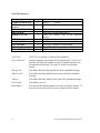
REVISION HISTORY
Version
1.0
Version
1.1
9/9/94
Original Release
12/9/9
4
Version
2.0
5/4/95
Revised, added and corrected Error Code documentation
Added ladder logic examples
Expanded description of the PLC Command Interface
Incorporated minor corrections and additions
Removed PLC logic section (now in 2572 IOG)
Added Packed task code description
Incorporated minor corrections and additions
Version
2.1
3/10/9
8
Added Memory Exchange command.
Documented additional address classes.
Deleted “Raw” NITP and “Embedded Task Code” descriptions.
Changed Chapter 3 title from “Troubleshooting” to “Application
Development” and included sections on performance and TCP/IP
coding.
CTI 2572 Programming Reference Manual V2.1
i
ii
CTI 2572 Programming Reference Manual V2.1
PREFACE
This Reference Manual is intended for individuals who wish to develop computer system
applications which interface to the CTI 2572 Ethernet TCP/IP Adapter.
Chapter 1 provides a summary of the module features and an overview of the software
development requirements. Chapter 2 describes the message formats used by the module
and provides coding examples.
For specific module hardware information, including module installation and checkout,
please refer to the CTI 2572 Ethernet TCP/IP Adapter Installation and Operation Guide
(2572 IOG), CTI Part Number 62-146. If you will be using task codes, you will need to
reference an applicable Siemens® publication, such as the SIMATIC® 575 Task Code
User Manual (Order # PPX:5575-8104-1).
We assume you are familiar with the installation and operation of SIMATIC® 505
programmable controllers. Please refer to the appropriate SIMATIC® user
documentation for specific information on SIMATIC® 505 programmable controllers
and I/O modules.
We also assume that you are familiar with TCP/IP concepts and programming
conventions.
Note:
On June 1, 1996, Siemens® Energy and Automation Inc. was granted exclusive rights to
market the CTI 2572 product as the Siemens® SIMATIC® 505-CP2572. The contents of
this manual fully apply to the 505-CP2572.
CTI 2572 Programming Reference Manual V2.1
iii
iv
CTI 2572 Programming Reference Manual V2.1
USAGE CONVENTIONS
NOTE:
Notes alert the user to special features or procedures
CAUTION:
Cautions alert the user to procedures which could damage equipment.
WARNINGS:
Warnings alert the user to procedures which could damage equipment and
endanger the user.
CTI 2572 Programming Reference Manual V2.1
v
vi
CTI 2572 Programming Reference Manual V2.1
TABLE OF CONTENTS
CHAPTER 1. 2572 OVERVIEW ........................................................................................... 1
1.1.
1.2.
1.3.
1.4.
Hardware Overview............................................................................................................................1
Functional Overview...........................................................................................................................2
TCP/IP Overview................................................................................................................................5
Programming Overview......................................................................................................................7
CHAPTER 2. 2572 MESSAGE PROTOCOL ....................................................................... 9
2.1.
2.2.
2.3.
2.4.
2.5.
2.6.
Overview.............................................................................................................................................9
CAMP Protocol Description ...............................................................................................................9
Memory Transfer Messages..............................................................................................................13
Packed Task Code Message..............................................................................................................27
CAMP Protocol Error Message ........................................................................................................33
CAMP Message Summary................................................................................................................34
CHAPTER 3. APPLICATION DEVELOPMENT ...............................................................35
3.1.
3.2.
3.3.
3.4.
3.5.
3.6.
Factors Affecting Performance .........................................................................................................35
Performance Enhancement Tips .......................................................................................................37
Coding Illustrations...........................................................................................................................41
Development and Debugging Tools .................................................................................................43
TCP/IP Problems ..............................................................................................................................43
CAMP Message Processing Problems..............................................................................................44
APPENDIX A. 2572 ERROR CODES..................................................................................45
CAMP Error Codes...................................................................................................................................45
NITP Task Code 00 Error Codes ..............................................................................................................49
APPENDIX B. ADDRESS CLASS INFORMATION .........................................................51
General Information..................................................................................................................................51
Common Data Types ................................................................................................................................51
Loop Data Types.......................................................................................................................................53
Alarm Data Types .....................................................................................................................................54
APPENDIX C. TASK CODE OVERVIEW .........................................................................57
APPENDIX D. REFERENCE MATERIAL .........................................................................61
TABLE 1. Hex to ASCII Conversion ......................................................................................................61
WX / WY Quick Reference ......................................................................................................................62
CTI 2572 Programming Reference Manual V2.1
vii
viii
CTI 2572 Programming Reference Manual V2.1
TABLE OF FIGURES
Figure 1. CTI 2572...............................................................................................................1
Figure 2. PLC Server Function ............................................................................................2
Figure 3. PLC Client Function.............................................................................................4
Figure 4. CAMP Message Format .......................................................................................9
Figure 5. CAMP Message Summary .................................................................................34
CTI 2572 Programming Reference Manual V2.1
ix
CHAPTER 1. 2572 OVERVIEW
1.1. Hardware Overview
The 2572 Ethernet TCP/IP Adapter is a single wide
I/O module for SIMATIC® 505 controllers. The
2572 provides connectivity to Ethernet local area
networks and allows the PLC to communicate with
other network nodes using the Transmission
Control Protocol/ Internet Protocol (TCP/IP) suite.
Using the 2572, other devices on the network can
acquire data from the PLC, send data and programs
to the PLC, and exercise supervisory control over
the PLC operation. In addition, the PLC can use
the facilities of the 2572 to send messages to
another node on the network.
The 2572 attaches to all Ethernet media specified
by IEEE 802.3 including 10Base5 ("thick" coaxial
cable), 10Base2 ("thin" coaxial cable), 10BaseT
(unshielded twisted pair cabling), FOIRL (fiber
optic cable) and 10BaseFL (fiber optic cable).
10BaseT cabling can be attached directly to the
2572 via an RJ-45 connector. Other IEEE 802.3
media may be connected to the AUI (Attachment
Unit Interface) port via a user supplied transceiver.
Figure 1. CTI 2572
The 2572 also provides two serial ports that can be
used as programming ports for the local PLC or
another PLC on the network. In addition, these ports can be used for module
configuration operations.
The 2572 module itself requires no customer programming. PLC logic can be used to
set module configuration and to control the operation of the module. Optionally, all
configuration options can be set by module switches and a serially attached personal
computer.
Please refer to the 2572 Installation and Operation Guide for additional details regarding
the hardware.
CTI 2572 Programming Reference Manual V2.1
1
1.2. Functional Overview
Modern network communication is based on the concept of a client-server relationship.
The client is a program on one network node that seeks a service, such as reading PLC
data, from another network node. The server is the responding program which can
provide the service.
The 2572 can operate as both a PLC server and a PLC client. As a PLC server, the 2572
responds to messages sent by another network node. As a PLC client, the 2572 initiates
messages on command from the PLC.
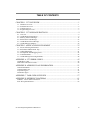
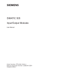
PLC Server Function
The 2572 functions as a server to clients who wish to access the PLC. The following
figure illustrates the typical message dialog between the client, the 2572, and the PLC.
1) Command Message
4) Response Message
Client Node
2
5
7
2
2) PLC Command
3) PLC Response
P
L
C
Server PLC / 2572
Figure 2. PLC Server Function
1)
The client node sends a command message to the 2572 via TCP/IP. For example,
the client may request that the 2572 read and return 25 words of V memory.
2)
Based on the contents of a command message, the 2572 sends commands and data
to the PLC processor via the backplane. For example, the 2572 would issue the
applicable command to the PLC to retrieve 25 words of V memory.
3)
The PLC processor responds to the command via the backplane. In the example,
the PLC would return 25 V memory words.
4)
After the PLC responds, the 2572 builds the appropriate message and returns it to
the client node. In this example, the 2572 would build a network message
containing the 25 words of data and send it to the client that requested it.
Messages between the 2572 and the client node are encapsulated in the TCP/IP protocol.
The client creates the 2572 command message and sends it to the server using UDP or
TCP. The response from the server is returned using the same delivery protocol. The
client node may be a suitably programmed computer or another 2572 on the network (see
next section).
2
CTI 2572 Programming Reference Manual V2.1
The 2572 will support multiple concurrent server sessions. To operate the CTI 2572 as a
PLC server, no PLC logic changes are required. However, you may choose to use PLC
logic to set the network parameters for the module.
CTI 2572 Programming Reference Manual V2.1
3
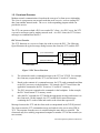
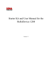
PLC Client Function
The 2572 can also function as a PLC Client. As a PLC Client, the 2572 acts as an agent
for the PLC; it sends messages to other nodes and processes the responses under control
of the PLC logic. Data in the PLC program specifies the recipient and data contents of
the message. PLC logic sets a “trigger” bit to cause the 2572 to send the message.
1) 2572 Command
P
L
C
4) 2572 Response
2
5
7
2
2) Command Message
3) Response Message
Client PLC / 2572
Server Node
.
Figure 3. PLC Client Function
1)
When the PLC detects a specified event, it sends a command to the local 2572.
For example, the command could be to read 5 words from another node on the
network.
2)
Based on the command, the 2572 sends the applicable command via TCP/IP to
the specified network (server) node.
3)
The server node processes the command and returns a response via TCP/IP. In
the example, the server node would return a message containing the specified
words.
4)
The 2572 processes the network message and notifies the PLC that the operation
is complete. In the example, the 2572 would place the words in a specified PLC
memory location and signal completion of the task.
The 2572 can support multiple concurrent client sessions. The server node shown in the
illustration could be another 2572 or a computer programmed to emulate a 2572 PLC
server.
The 2572 can support multiple server sessions and multiple client sessions concurrently.
Therefore, networked PLCs can use the facilities of the 2572 to participate in multisession peer-to-peer communications.
4
CTI 2572 Programming Reference Manual V2.1
1.3. TCP/IP Overview
The 2572 uses TCP/IP (Transmission Control Protocol/Internet Protocol) to transport
messages between the module and other nodes on the network. TCP/IP provides routing
and delivery services for messages between application programs running on different
processors (called hosts in TCP/IP terminology). You may select between connectionless
(packet based) or connection-oriented (stream based) delivery services.
Connectionless Delivery
Connectionless delivery services allow you to send a message to another node without
previously establishing a logical connection to the other node. TCP/IP provides a format
known as the User Datagram Protocol (UDP) for sending and receiving connectionless
messages. Connectionless delivery is simple to implement and consumes a small amount
of system resources. However, delivery of UDP messages is not confirmed by the
network protocol. It is up to cooperating application programs to acknowledge receipt.
The application message protocols used with the 2572 will acknowledge receipt of a
command message.
Connection-Oriented Delivery
With connection-oriented services, you must first establish a logical connection (known
as a virtual circuit) before network nodes can exchange messages. TCP/IP uses the
Transmission Control Protocol (TCP) format to implement connection-oriented services.
TCP provides guaranteed delivery and message flow control. TCP is stream oriented,
meaning the application program sees a properly sequenced stream of data rather than
individual packets. TCP is often used for file transfer applications such as program
downloads. You may also choose to use TCP when you want to ensure that the other
node is available before you send a message.
Socket Interface
TCP/IP uses a standard structure known as a socket, for the application program
interface. The de facto socket standard is the Berkeley Socket, named for the University
of California at Berkeley, who originally distributed TCP/IP. Originally, the Berkeley
Sockets were used with only the Unix operating system. Today, software which
implements the Berkeley Socket standard is available for MS-DOS, IBM OS/2, and
Microsoft Windows. Microsoft, in conjunction with several TCP/IP software providers,
has established the Winsock standard to promote interoperability among TCP/IP software
using Windows.
Summary
TCP/IP has the largest market share of any network protocol. Because it is based on
open standards and has proven to be practical and reliable, the use of TCP/IP is growing
dramatically. TCP/IP can be implemented with most PC, network, and minicomputer
operating systems. Originally used by defense contractors and government facilities,
TCP/IP is making major inroads into other segments of the industrial market. One
important application of TCP/IP is communication among factory controller systems and
CTI 2572 Programming Reference Manual V2.1
5
supervisory workstations. For more information on TCP/IP features and services please
refer to one of the TCP/IP publications commonly available at bookstores. An excellent
reference is Internetworking with TCP/IP by Douglas Comer (1991, Prentice Hall).
6
CTI 2572 Programming Reference Manual V2.1
1.4. Programming Overview
PLC Logic
If you are using the 2572 as a PLC server only, you are not required to provide any
external PLC logic other than those required to set the network address parameters. The
standard 2572 PLC Network Server function will reply to commands sent over TCP/IP
from a client node.
If you are using the PLC Client function of the 2572, you will need to develop PLC logic
to control the operation of the module. For example, if you want the 2572 to send a
message when a particular event occurs, you will need to add the PLC logic to trigger the
appropriate module command. The PLC logic for client Operations is described in the
2572 Installation and Operation Guide.
Computer TCP/IP Support
The 2572 uses the TCP/IP protocol to transport data across the network. If you are
programming on a UNIX machine, TCP/IP is a component of the operating system.
Microsoft Windows and IBM OS/2 also provide TCP/IP drivers. If you are writing a
DOS application, you will need to obtain this software from third party sources.
Microsoft has established a standard specification known as Winsock, which provides a
common API for all Windows applications. The Winsock specification may be obtained
from Microsoft via the Microsoft Internet FTP site, Microsoft Download Services, or the
applicable Microsoft Software Development kit. Microsoft TCP/IP protocol stacks are
available for Windows for Workgroups, Windows 95, and Windows NT. Windows 95
and Windows NT include TCP/IP support with the operating system. For Windows for
Workgroups, you must obtain stack from Microsoft. The TCP/IP-32 stack may be
downloaded from Microsoft Download Services or from their Internet FTP site.
Due to the increasing popularity of TCP/IP, there are a number of development tools
which make it easy to send and receive messages via TCP/IP. In particular, several
vendors offer “custom controls” for TCP/IP. Custom Controls are objects which may be
used with Microsoft Visual BASIC and Visual C++. By manipulating the properties of
the custom control, a developer can cause the object to perform TCP/IP operations
including connect, send, receive and disconnect. Since the custom control makes the
appropriate socket calls, the programmer is relieved of this task.
Application Logic
If you want to use a computer system as a client node (using the PC to access the PLC),
your software must create the 2572 command message and process the response returned
by the 2572. If you wish to process unsolicited messages from the 2572 (where the 2572
is a client), you will need to provide software which emulates the 2572 PLC server
function. The 2572 message protocol is described in Chapter 2 of this manual.
CTI 2572 Programming Reference Manual V2.1
7
CHAPTER 2. 2572 MESSAGE PROTOCOL
2.1. Overview
The 2572 uses TCP/IP as a means to transport messages over the network. Messages
which contain 2572 commands and responses are encapsulated in the TCP/IP protocol.
CTI uses a protocol known as CAMP (Common ASCII Message Protocol) to send the
commands and to process the responses.
CAMP is used with all CTI communications products, including the CTI 2572. CAMP
can be used over serial data links as well as over Ethernet networks. It has been designed
to provide a sufficiently robust protocol while keeping the programming requirements
simple. CAMP allows you to transfer large blocks of memory as well as to send vendor
specific commands such as Siemens® SIMATIC® 505 Task codes.
CAMP is a command/response protocol. When a CAMP command is sent to another
node, a response is expected. This dialog allows the application to determine whether a
command was successfully completed. By providing delivery confirmation, CAMP
provides reliability to connectionless (UDP) delivery.
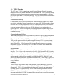
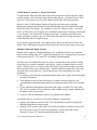
2.2. CAMP Protocol Description
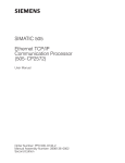
Message Format
CAMP messages use ASCII character format. The figure below illustrates the message
format:
• The message begins with an ASCII left bracket [ (0x5B),
• The type field identifies the type of data contained in the message data area,
• The error character is used to flag an error in the protocol or message data,
• The Message ID character is used to add an identifier to the message,
• The message data area contains command or response messages in a format indicated
by the type field,
• The block check character (BCC) field is a checksum on the message,
• The message ends with an ASCII right bracket ] (0x5D).
Message
Start Delimiter
Message
Type
Error
Character
Message
ID
Data
Block Check
Characters
Message
End Delimiter
Figure 4. CAMP Message Format
CTI 2572 Programming Reference Manual V2.1
9
Numeric Data Representation
All numeric data within the CAMP packet is encoded Hexadecimal ASCII (Hex-ASCII).
Hex-ASCII represents the hexadecimal equivalent of a byte as two ASCII characters.
For example, if the hexadecimal equivalent of a byte is 0A, the message would contain
the ASCII character 0 (0x30) followed by the ASCII character A (0x41). Valid HexASCII characters are:
• ASCII 0 - 9 (0x30 - 0x39)
• ASCII A - F (0x41 through 0x46).
Representing numeric data as Hex-ASCII provides several benefits. First, it simplifies
communications programming. Since the valid characters which define the data are
limited, other characters not used for data can be chosen for control characters. Therefore,
when you receive a character representing a message control, you can assume that it is not
data. In contrast, a binary protocol must rely on certain byte sequences to represent control
characters since the data byte can be any hex value. Second, Hex-ASCII provides a
standard data representation independent of the way binary data is actually stored in
memory. Therefore the programmer does not have to translate between PLC data format
and PC data format. Since the message length is generally short and PLC scan times are
relatively long, the lack of protocol density does not affect overall performance
significantly.
Hex-ASCII Character Order
In Hex-ASCII, the character representing the high nibble of the byte is transferred first
followed by the character representing the low nibble of the byte. CAMP uses 16 bit
words in which the characters representing the most significant byte are transferred first,
followed by the characters representing the least significant byte. Thus, values will
appear in “natural” order on a protocol analyzer.
Message Identification
The CAMP protocol provides a single character message ID field which can be used by an
application program to tag a message. By assigning a unique message ID to the message,
the application can associate a response with a particular command. The allowable ID
characters are ASCII 0-9 and A-F.
The 2572 Client function will cycle through the allowable characters when generating a
command message and will reject replies which do not have a matching message ID.
Programs which implement a server function are expected to behave like a 2572 server and
echo the message ID in the response message.
Block Check Characters
The four block check characters (BCC) are the Hex-ASCII equivalent of a 16 bit word.
The BCC immediately precedes the message terminating character. The calculations do
not include the message delimiters ([ or ]).
10
CTI 2572 Programming Reference Manual V2.1
CTI 2572 Programming Reference Manual V2.1
11
To derive the BCC:
1. Convert any binary data to Hex-ASCII characters,
2. Add the lower 7 bits of each ASCII character to a 16 bit unsigned accumulator, ignoring
carries,
3. Convert the 16 bit accumulator to 4 digit Hex-ASCII BCC field.
For example, assume you want to send a message containing the ASCII character F (0x46)
followed by the ASCII character 3 (0x33). The result of performing a binary add on the
characters is 0x79 (0x46 + 0x33). Thus, the BCC field contains the ASCII characters 0079
(0x30 30 37 39). See more examples later in this chapter.
To check the BCC:
1. Add the lower 7 bits of each character to an unsigned16 bit accumulator, ignoring
carries,
2. Convert the BCC to binary and compare to the above or convert the accumulator to
HEX ASCII and compare with the BCC.
Command / Response Design
CAMP is a command /response protocol. When you send a command message, the
recipient should reply. This provides positive confirmation that the message was
received. The TYPE field indicates whether the message is a command or a response.
Software performing a server function should always reply to a command message
indicating successful completion or that an error condition was encountered. Software
performing a client function should respond to a command message with an error reply,
since a client cannot act on a command. Software (server or client) should never reply to
a response message.
The command/response protocol should be observed by your application regardless of the
underlying TCP/IP protocol chosen. Even when using TCP, the network protocol
guarantees only that the application will be notified if TCP cannot deliver the message to
the 2572 after several retries. It does not guarantee the PLC is able to process the
encapsulated command which the 2572 delivers to the PLC. The CAMP response will
provide notification of the PLC command processing.
Message Types
The CAMP protocol supports both device-independent message formats and vendor
specific formats. The 2572 provides CAMP support for the memory transfer format
(device independent) and SIMATIC® 505 Task Code (vendor specific). The module
also supports the CAMP general error message type. These are described in the
following sections.
12
CTI 2572 Programming Reference Manual V2.1
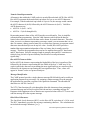
2.3. Memory Transfer Messages
Memory transfer messages are used to send word-oriented data between processors. The
2572 maps these words to PLC memory. A significant benefit of this type is that it allows a
large number of words to be sent in a single message packet.
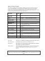
Read Data Command
Description
Length
1
START OF MESSAGE
2
TYPE
1
ERROR
CHARACTER
1
MESSAGE ID
4
ADDRESS CLASS
4
ADDRESS WORD
2
WORD COUNT
4
DATA WORD 1
4
BCC
1
END OF MESSAGE
Value
ASCII [
ASCII 04
ASCII 0
(0x5B)
(Read Data Command)
ASCII 0-9, A-F
ASCII 0000
Hex ASCII representing a 16 bit address
ASCII 01
Hex ASCII - Number of words to be read (1-256)
Hex ASCII representing 16 bits of checksum data
ASCII ]
(0x5D)
Type Field:
ASCII 04 is a command to Read Data from the remote device.
Error Character:
Commands always have the error character set to 0.
Message ID:
This character is set by the program which initiates the command.
The response will echo the message ID. The message ID must be a
valid hex-ASCII character (0-9, A-F).
Address Class:
This field specifies the particular type of memory to be accessed.
A value of 0000 indicates the default memory type of PLC V
memory. See Appendix B regarding the use of other Address
Class values with the 2572.
Address:
This is the beginning address of the memory to be read or written.
For Address Class 0000, this is the V memory number. For
example, a value of 100 represents V100.
Word Count:
This is a count of the number of data words contained in the
message.
Data Word 1:
This is the number of data words to be read from the remote
device. Maximum = 256 words.
CTI 2572 Programming Reference Manual V2.1
13
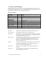
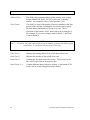
Read Data Response
Description
START OF MESSAGE
TYPE
ERROR CHARACTER
MESSAGE ID
ADDRESS CLASS
Length
1
2
1
1
4
ADDRESS
WORD COUNT
4
2
DATA WORD 1
DATA WORD 2
..
..
DATA WORD n
BCC
4
4
..
..
4
4
Value
ASCII [
(0x5B)
ASCII 05
(Read Data Response)
ASCII 0
Echoes the Command Message ID
Echoes the Address Class in the command
message
Echoes the Address in the command message
Hex ASCII indicating the number of data words
read
Hex ASCII representing a 16 bit data word
Hex ASCII representing a 16 bit data word
..
..
Hex ASCII representing a 16 data word
Hex ASCII representing a 16 bit checksum
END OF MESSAGE
1
ASCII ]
(0x5D)
Type Field:
ASCII 05 is a response to a Read Data command.
Error Character:
Valid responses will contain ASCII 0 in this field. If an error is
detected, this field will contain an ASCII F and the data area will
contain error information. See page 23 for the error message
format.
Message ID:
This field echoes the Message ID sent in the command message.
Address Class:
This field echoes the Address Class value sent in the command
message.
Address:
This field echoes the Address value sent in the command message.
Word Count:
This field is a count of the number of data words contained in the
message.
NOTE:
For 1 - 255 words, the word count will be set to the number of data words following the
word count. A word count 00 represents 256 words.
14
CTI 2572 Programming Reference Manual V2.1
Data Words 1-n
These data words are the Hex-ASCII equivalent of the numeric
data. Up to 256 words can be included in one CAMP message.
CTI 2572 Programming Reference Manual V2.1
15
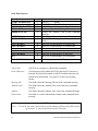
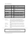
Write Data Command
Description
Length
1
START
OF
MESSAGE
2
TYPE
1
ERROR
CHARACTER
1
MESSAGE ID
4
ADDRESS CLASS
4
ADDRESS.
2
WORD COUNT
4
DATA WORD 1
4
DATA WORD 2
..
..
..
..
4
DATA WORD n
4
BCC
1
END OF MESSAGE
Value
ASCII [
ASCII 06
ASCII 0
(0x5B)
(Write Data Command)
ASCII 0-9 A-F
ASCII 0000
Hex ASCII representing a 16 bit memory address
Hex ASCII indicating the number of data words
Hex ASCII representing 16 bits
Hex ASCII representing a 16 bit data word
..
..
Hex ASCII representing a 16 bit data word
Hex ASCII representing a 16 bit checksum
ASCII ]
(0x5D)
Type Field:
ASCII 06 is a command to Read Data from the remote device.
Error Character:
Commands always have the error character set to 0.
Message ID:
This character is set by the program which initiates the command.
The response will echo the message ID.
Address Class:
This field specifies the particular type of memory to be accessed.
A value of 0000 indicates the default memory type of PLC V
memory. See Appendix B regarding the use of other Address
Class values with the 2572.
Address:
This field is the beginning address of the memory to be read or
written. For Address Class 0000, this is the V memory number.
For example, a value of 100 represents V100.
Word Count:
This field is a count of the number of data words contained in the
message.
NOTE:
For 1 - 255 words, the word count will be set to the number of data words following the
word count. A word count 00 represents 256 words.
16
CTI 2572 Programming Reference Manual V2.1
Data Words 1-n
These words are the Hex-ASCII equivalent of the numeric data.
Up to 256 words can be included in one CAMP message.
CTI 2572 Programming Reference Manual V2.1
17
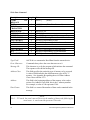
Write Data Response
Description
Length
1
START OF MESSAGE
2
TYPE Write
Data
Response
1
ERROR CHARACTER
1
MESSAGE ID
4
ADDRESS CLASS
ADDRESS
WORD COUNT
DATA WORD1
BCC
END OF MESSAGE
4
2
4
4
1
Value
ASCII [
ASCII 07
(0x5B)
ASCII 0
Echoes the Command Message ID
Echoes the Address Class in the command
message
Echoes the Address in the command message
ASCII 01
Hex ASCII - Number of words written
Hex ASCII representing a 16 bit checksum
ASCII ]
(0x5D)
Type Field:
ASCII 07 is a response to a Write Data command.
Error Character:
Normal responses will contain ASCII 0 in this field. If an error is
detected, this field will contain an ASCII F and the data area will
contain error information. See page 23 for the error message
format.
Message ID:
This field echoes the Message ID sent in the command message.
Address Class:
This field echoes the Address Class value sent in the command
message.
Address:
This field echoes the Address value sent in the command message.
Word Count:
This field is set to 01.
Data Word 1:
This word represents the number of words successfully written. If
the write was not successful an error response will be returned.
18
CTI 2572 Programming Reference Manual V2.1
Memory Exchange Command
The memory exchange format facilitates a high speed memory transfer between two
devices. Essentially this is a combination of a CAMP memory write and a CAMP
memory read. The command contains the data to be written to the remote device. The
response contains the data read from the remote device.
Description
START OF
MESSAGE
TYPE
ERROR
CHARACTER
MESSAGE ID
ADDRESS Class
ADDRESS
Lengt
h
1
Value
ASCII [
(hex 5B)
2
1
ASCII 08
ASCII 0
(Memory Exchange Command)
1
4
4
ASCII 0-9 A-F
ASCII 0000 = Default Class
Hex ASCII representing a 16 bit memory address
to which data will be written
Hex ASCII indicating the number of data words in the
message
HexASCII Address from which data will be read
Hex ASCII Number of words to be read
HexASCII representing 1st word of PLC data to be
written
WORD COUNT
2
DATA WORD 1
DATA WORD 2
DATA WORD 3
4
4
4
..
DATA WORD n
4
BCC
END OF MESSAGE
4
1
Hex ASCII representing last word of PLC data to be
written
Hex ASCII representing a 16 bit checksum
ASCII ]
(hex 5D)
Type Field:
ASCII 08 is a command to Exchange Data from the remote device.
Error Character:
Commands always have the error character set to 0.
Message ID:
This character is set by the program which initiates the command.
The response will echo the message ID.
Address Class:
This field specifies the particular type of memory to be accessed.
A value of 0000 indicates the default memory type of PLC V
memory.
NOTE:
When using the Exchange Data command, the Address Class should always be set to
0000.
CTI 2572 Programming Reference Manual V2.1
19
Address Write:
This field is the beginning address of the memory to be written.
For the SIMATIC® Series 505 PLCs, this is the V memory
number. For example a value of 100 represents V100.
Word Count:
This field is a count of the number of words contained in the data
portion of the message, including the two words used to specify
the read address and number of words to be read. This is
equivalent to the number of PLC data words to be written plus 2.
For example, if you were writing 6 words to the PLC, the Word
Count would be 8.
NOTE:
For 1 - 255 words, the word count will be set to the number of data words following the
word count. A word count 00 represents 256 words.
Data Word 1
Indicates the starting address from which data will be read.
Data Word 2
Indicates the number of data words to be read.
Data Word 3
Contains the first data word to be written. These words are the
Hex-ASCII equivalent of the numeric data.
Data Words 4 - n
Contain additional data words to be written. A maximum of 254
words can be written using this message format.
20
CTI 2572 Programming Reference Manual V2.1
Memory Exchange Response
Description
START OF MESSAGE
TYPE
ERROR CHARACTER
MESSAGE ID
ADDRESS CLASS
Length
1
2
1
1
4
ADDRESS
WORD COUNT
4
2
DATA WORD 1
DATA WORD 2
..
..
DATA WORD n
BCC
4
4
..
..
4
4
Value
ASCII [
(0x5B)
ASCII 09
(Memory Exchange Response)
ASCII 0
Echoes the Command Message ID
Echoes the Address Class in the command
message
Echoes the Address in the command message
Hex ASCII indicating the number of data words
read
Hex ASCII representing a 16 bit data word
Hex ASCII representing a 16 bit data word
..
..
Hex ASCII representing a 16 data word
Hex ASCII representing a 16 bit checksum
END OF MESSAGE
1
ASCII ]
(0x5D)
Type Field:
ASCII 09 is a response to a Memory Exchange command.
Error Character:
Valid responses will contain ASCII 0 in this field. If an error is
detected, this field will contain an ASCII F and the data area will
contain error information. See page 23 for the error message
format.
Message ID:
This field echoes the Message ID sent in the command message.
Address Class:
This field echoes the Address Class value sent in the command
message.
Address:
This field echoes the Address value sent in the command message.
Word Count:
This field is a count of the number of data words contained in the
message.
NOTE:
For 1 - 255 words, the word count will be set to the number of data words following the
word count. A word count 00 represents 256 words.
CTI 2572 Programming Reference Manual V2.1
21
Data Words 1-n
22
These data words are the Hex-ASCII equivalent of the numeric
data. Up to 256 words can be included in one CAMP message.
CTI 2572 Programming Reference Manual V2.1
Command Error Response
If an error occurs when processing the contents of the data field (which could be caused
by an invalid address, invalid number of words specified, or a PLC processing error),
then a Command Error response will be returned. The format is as follows:
Description
START OF MESSAGE
TYPE
Read Data Response
Write Data Response
Memory Exchange
Resp.
ERROR CHARACTER
MESSAGE ID
Length
1
2
Value
ASCII [
(0x5B)
ASCII 05
ASCII 07
ASCII 09
1
1
ADDRESS CLASS
4
ADDRESS
WORD COUNT
MODULE ID
PROTOCOL
MANAGER NO.
ERROR CODE
EXTENDED ERROR
INFORMATION
BCC
4
2
4
4
ASCII F
(Echoes the message ID sent in the command
message)
(Echoes the address class sent in the command
message)
(Echoes the address sent in the command message)
ASCII 04
Hex ASCII
Hex ASCII
4
4
Hex ASCII (See Appendix A)
ASCII
4
END OF MESSAGE
1
Hex ASCII Characters representing a 16 bit
checksum
ASCII ]
(0x5D)
Type Character:
ASCII 05 is a response to a Read Data command.
ASCII 07 is a response to a Write Data command.
ASCII 09 is a response to a Memory Exchange command.
Error Character:
Always set to ASCII F for a data error
Message ID:
The message ID field will contain the message ID sent in the
command message.
Address Class:
The address class field will contain the address class sent in the
command message.
Address:
The address field will contain the address sent in the command
message.
CTI 2572 Programming Reference Manual V2.1
23
Word Count:
The word count is set to ASCII 04 to indicate that there are 4 error
data words.
Module ID:
The Module ID is provided by CTI modules to help in problem
diagnosis. This field for user information only; the value in this
field is ignored by CTI 2572 error processing logic. Your software
can set this to any valid Hex-ASCII value when returning an error
message.
Protocol Manager ID:
The protocol manager ID is provided by CTI software to
help in problem diagnosis. This field for user information only;
the value in this field is ignored by CTI 2572 error processing
logic. Your software can set this to any valid Hex-ASCII value
when returning an error message.
Error Code:
The error code describes the specific error detected. Appendix A
describes the error codes in detail.
Extended Error Info: This word is used for extended error information by some error
responses.
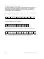
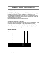
Read Data Command /Response Example
The command ADDRESS WORD contains the starting memory address in the remote
device and the first DATA word contains the number of words to be read. The response
echoes the ADDRESS WORD contained in the command, sets the WORD COUNT to
the actual number of words read, and places the requested words in the CAMP message
following the word count.
For example, assume you want to read 3 words beginning at V memory location 5 in the
remote PLC. Assuming the message ID is set to 0, the read data command message would
be:
Char
Hex
Msg
Start
[
5B
Type
04
30 34
Er
r
0
30
ID
Class
Address
Count
Data
BCC
0
30
0000
30 30
30 30
0005
30 30
30 35
01
30 31
0003
30 30
30 33
036D
30 33
36 44
Msg
End
]
5D
Where the BCC is calculated as:
BCC = (30+34)+30+30+(30+30+30+30)+(30+30+30+35)+(30+31)+(30+30+30+33) =
036D
Assuming that the memory locations contain the decimal values 6, 12, and 21
(0x0006,000C, and 0015), the normal response message would be :
Msg
Start
[
24
Type
05
Err
0
ID
0
Class
0000
Address
0005
Count
03
Word1
0006
Word2
000C
Word3
0015
BCC
050C
Msg
End
]
CTI 2572 Programming Reference Manual V2.1
If the 2572 were unable to read the V memory, it would return the following error response:
Msg
Start
[
Type
05
Err
F
ID
0
Class
0000
Addr
0005
Count
04
Mod
ID
2572
PM
No.
0023
Error
Code
00AC
Resv
0000
BCC
05FD
Msg
End
]
The error code AC indicates a memory read error (See Appendix A).
CTI 2572 Programming Reference Manual V2.1
25
Write Data Command / Response Example
The command ADDRESS WORD contains the starting address in the remote device and
the WORD COUNT contains the number of words to be written. The word data is
included in the data section of the message. The response echoes the MESSAGE ID,
THE ADDRESS CLASS, and the ADDRESS.
Assuming the message ID is set to 1, the following example message writes 3 words of
decimal value 12, 33, and 4 (0x0C,0x21, and 0x04) starting at V memory location V10.
Msg
Start
[
Type
06
Err
0
ID
1
Class
0000
Addr
000A
Count
03
Word1
000C
Word2
0021
Word3
0004
BCC
0515
Msg
End
]
The normal response from the 2572 should be:
Msg
Start
[
Type
07
Err
0
ID
1
Class
0000
Addr
000A
Count
01
Word1
0003
BCC
02B9
Msg
End
]
If the 2572 server were unable to write V memory, it would return an error message of:
Msg
Start
[
Type
07
Err
F
ID
1
Class
0000
Addr
000A
Count
04
Mod
ID
2572
PM
No.
0023
Error
Code
00AD
Rsvd
0000
BCC
060D
Msg
End
]
The error code 0xAD indicates an error writing V memory (see Appendix A).
26
CTI 2572 Programming Reference Manual V2.1
2.4. Packed Task Code Message
Siemens® SIMATIC® 505 PLCs support a command protocol known as Task Codes.
Using task codes, an application can access most of the variable types within the PLC.
For example, programming software such as TISOFT uses task codes to program the
PLC. Similarly, Operator Interface panels use Task Codes to read and write to the PLC.
See APPENDIX C. TASK CODE SUMMARY for additional information.
Typically, task codes are transmitted via serial communications using the Non Intelligent
Terminal Protocol (NITP) or the Transparent Binary Protocol (TBP). The 2572 allows
task codes in NITP message format to be transmitted via TCP/IP. In addition, the 2572
supports a much denser (and therefore higher performance) variation known as CAMP
Packed Task Code.
The CAMP Packed Task Code message format allows multiple task code messages to be
enclosed in a single CAMP message packet. The task code messages are formatted per
the SIMATIC® TI500/505 NITP (Non-Intelligent Terminal Protocol) specifications,
except that the beginning and ending delimiters are omitted. The responses to the packed
task code messages will be placed in the CAMP response message in the same order as
they were received. For example, the response to the second task code message in the
CAMP command message will be returned in the second task code message in the CAMP
response message.
NOTE:
Before placing the NITP message in a CAMP packet, you must strip off the NITP
message delimiters (colon and semicolon).
CTI 2572 Programming Reference Manual V2.1
27
Message Format
The message format is described below. You can cause the CAMP server to bypass
NITP error checking for a task code message by setting the NITP checksum to 4 ASCII
Question Marks (????). The CTI PLC Server function will always generate the NITP
checksums in the response; you may choose to ignore it. You can include up to 14 task
codes messages in one CAMP message.
Description
Start Of Message
Type
Device Specific Command
Device Specific Response
Error Character
Message ID
Device Class
Reserved (Unused)
Reserved (Unused)
Msg 1: NITP Character Count
Msg 1: Task Code
Msg 1: Task Code Data
Msg 1: NITP Err Check Char
Msg 2: NITP Character Count
Msg 2: Task Code
Msg 2: Task Code Data
Msg 2: NITP Err Check Char
Length
1
2
Value
ASCII [
(0x5B)
ASCII 02
ASCII 03
1
ASCII 0
1
ASCII 0-9 A-F
4
ASCII 0001
4
ASCII 0000
2
ASCII 00
2
Hex ASCII representing an 8 bit number
2
Hex ASCII
variable Hex ASCII
4
Hex ASCII representing 16 data bits
Set to ASCII ???? = 0x3F3F3F3F to
ignore
2
Hex ASCII representing an 8 bit number
2
Hex ASCII
variable Hex ASCII
4
Hex ASCII representing 16 data bits
Set to ASCII ???? = 0x3F3F3F3F to
ignore
Repeat up to 14 task code
messages.
Msg n: NITP Character Count
Msg n: Task Code
Msg n: Task Code Data
Msg n: NITP Err Check Char
BCC
28
2
2
variable
4
4
Hex ASCII representing an 8 bit number
Hex ASCII
Hex ASCII
Hex ASCII representing 16 data bits
Set to ASCII ???? = 0x3F3F3F3F to
ignore
Hex ASCII - representing a 16 bit
CTI 2572 Programming Reference Manual V2.1
1
End Of Message
Type :
checksum
ASCII ]
(0x5D)
ASCII 02 indicates a Device Specific command. ASCII 03
indicates an Device Specific response.
Error Character:
response.
Always set to ASCII 0 for a command and a valid
Message ID:
This character is set by the program which initiates the command.
The response will echo the message ID.
Device Class:
ASCII 0001 is used to indicate SIMATIC® 505 packed task code
format.
Reserved:
These fields are reserved for future use. They should be set to 0 in
the command.
Character Count:
The NITP character count is calculated exactly as specified in
SIMATIC® documentation. Although you do not place the NITP
starting and ending delimiters in the CAMP packet, they are still
added to the NITP character count. This approach allows you to
use the same character count and checksum as you would when
sending standard NITP messages. Thus, the NITP character count
includes the number of characters in the character count, the task
code, the task code data, and the NITP checksum plus 2. The
valid range for character count is 10-72 (0x0A - 0x48).
Task Code:
The task code is a hexadecimal number represented by two ASCII
characters. See the SIMATIC®/TI documentation for a complete
description of the task codes.
Task Code Data:
The task code data is dependent upon the task code, See the
SIMATIC®/TI documentation.
NITP Err Check:
This is a checksum on the NITP characters. See the
SIMATIC®/TI documentation for details. If you do not wish to
calculate the checksum, set the checksum characters to ASCII ????
(0x3F3F3F3F).
CTI 2572 Programming Reference Manual V2.1
29
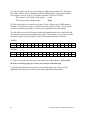
Message Processing Example
The following example reads one word from V memory location 3 and writes one word
to V memory location 4. Note that the message address fields are 0002 and 0003, since
NITP uses a 0 offset . The NITP Error Check Characters (ECC) were set to ???? (ASCII
question marks) to avoid eliminate calculations and the Message ID was set to 0. The
first NITP character count = 2 (count) +2 (task code)+4 (address ) +4 (ECC) +2 = 14
(0x0E). The second NITP character count = 2 (count) + 2 (task code) + 4 (address) + 4
(data) + 4 (ECC) + 2 = 18 (0x12).
Msg
Start
[
Type
02
Err
0
NITP
Count
12
Task
Code
02
Mem
Addr1
0003
Msg
ID
0
Data
1900
Device
Code
0001
NITP
ECC
????
Rsvd
0000
BCC
0885
Rsvd
00
NITP
Count
0E
Task
Code
01
Mem
Addr1
0002
NITP
ECC
????
Msg
End
]
NOTE:
The memory addresses in NITP are 0 relative. Memory address 0 will retrieve the first V
memory location.
Assuming V memory location 2 contains a value of 2000, the response would be:
Msg
Start
[
Type
03
Err
0
NITP
Count
0A
Task
Code
02
NITP
ECC
F5FE
30
Msg
ID
0
BCC
072C
Device
Code
0001
Rsvd
0000
Rsvd
00
NITP
Count
0E
Task
Code
01
Mem
Value
07D0
NITP
ECC
EA2F
Msg
End
]
CTI 2572 Programming Reference Manual V2.1
Command Error Response
Once the CAMP message has passed all CAMP protocol checks, is received without
error, then the module will sequentially evaluate each task code message for a valid
length and for the checksum data. If an error is detected during this evaluation, message
processing will be suspended and the module will return a CAMP Command Error
response. The format is as follows:
Description
Start Of Message
Type Device Specific
Response
Error Character
Message ID
Length
1
2
1
1
Device Class
4
Address (not used)
Word Count
Module ID
Protocol Manager No.
Error Code
Task Code Message No.
BCC
4
2
4
4
4
4
4
End Of Message
1
Value
ASCII [
ASCII 03
(0x5B)
ASCII F
(Echoes the message ID sent in the command
message)
(Echoes the device class sent in the command
message)
ASCII 0000
ASCII 04
ASCII Characters 0-9, A-F
Hex ASCII
Hex ASCII (See Appendix A)
Hex ASCII (0001 - 000E)
Hex ASCII Characters representing a 16 bit
checksum
ASCII ]
(0x5D)
Type Character:
ASCII 03 is a response to a Device Specific command.
Error Character:
Always set to ASCII F for a data error
Message ID:
The message ID field will contain the message ID sent in the
command message.
Address Class:
The device class field will echo the device class sent in the
command message.
Address:
The address field is not used in this response. It will be set to
0000.
Word Count:
The word count is set to ASCII 04 to indicate that there are 4 error
data words.
Module ID:
The Module ID is provided by CTI modules to help in problem
diagnosis.
CTI 2572 Programming Reference Manual V2.1
31
Protocol Manager ID:
The protocol manager ID is provided by CTI software to
help in problem diagnosis.
Error Code:
The error code describes the specific error detected. Appendix A
describes the error codes in detail.
Task Code Message #:
This word identifies which task code message contained
the error. For example, if the error was located in the third task
code message with the CAMP message, this word would contain
the value 0003.
Once all task code messages are verified for correct checksum and length, then they are
sent to the PLC in a group. Up to eight task codes can be processed in a single scan; the
actual number depends upon the PLC setting for number of task codes per scan.
Responses from the PLC will be placed in the CAMP response message in the same order
as the corresponding command.
If the PLC processor returns a task code error, the error response will be placed in the
CAMP response message in place of the normal response.
NOTE:
A type 00 task code response is not considered to be a CAMP error and will not cause
the CAMP error character to be set. A task code 00 is an error response from the PLC
processor, not from the 2572. If you use Packed Task Codes, you should check each task
code response for a task code 00 and process the result accordingly. See Appendix A
for a listing of the task code 00 error codes.
NOTE:
For best performance using this message format, you should set the number of task codes
per scan on the PLC to the maximum available (typically 8). If you are using TISOFT,
this can be set by using Aux Function 19.
32
CTI 2572 Programming Reference Manual V2.1
2.5. CAMP Protocol Error Message
A CAMP Protocol Error message (Type FF) is returned when a CAMP protocol error is
detected. CAMP protocol errors include missing delimiters, bad checksum, and invalid
type. The format of the type FF error message is identical to other CAMP error
messages. Since the content of the message packet is suspect when a CAMP protocol
error is detected, the message ID (and other fields which are usually echoed) are all set to
0.
Description
START OF MESSAGE
TYPE CHARACTER
ERROR CHARACTER
MESSAGE ID
UNUSED
UNUSED
WORD COUNT
MODULE ID
PROTOCOL
MANAGER NO.
ERROR CODE
RESERVED
BCC
END OF MESSAGE
Length
1
2
1
1
4
4
2
4
4
4
4
4
1
Value
ASCII [
ASCII FF
ASCII F
ASCII 0
ASCII 0000
ASCII 0000
ASCII 04
4 Hex-ASCII Characters
4 Hex-ASCII Characters
4 Hex-ASCII Characters (See Appendix A)
ASCII 0000
4 Hex-ASCII characters
ASCII ]
The following is a CAMP error message where an invalid type code was detected.
Msg
Start
[
Type
FF
Err
F
Msg
ID
0
Unused
0000
Unused
0000
CTI 2572 Programming Reference Manual V2.1
Count
04
Mod
ID
2572
PM
No.
0023
Error
Code
007B
Rsvd
0000
BCC
0614
Msg
End
]
33
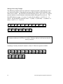
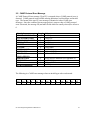
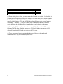
2.6. CAMP Message Summary
The following table summarizes the CAMP message formats described in the previous
sections. In the table, n represents any valid Hex-ASCII character (0-9, A-F) and cccc
represents 4 block check characters.
Msg
Start
[
Type
04
Err
0
Msg
ID
n
Class
Dev Cl
nnnn
Addr/
Message
Read Data Cmd
nnnn
Word
Count
01
Read Data Resp
Write Data Cmd
[
[
05
06
0
0
Echo
n
Echo
nnnn
Echo
nnnn
nn
nn
Write Data Resp
Mem Exch Cmd
[
[
07
08
0
0
Echo
n
Echo
0000
Echo
nnnn
00
nn
Mem Exch Resp
Cmd Error Resp
Packed T/C Cmd
Packed T/C Resp
Protocol Error
[
[
[
[
[
09
**
02
03
FF
0
F
0
0
F
Echo
Echo
n
n
0
Echo
Echo
0001
Echo
0000
Echo
Echo
0000
Echo
0000
nn
04
nn
nn
04
Data
Area
# words
to read
Data
Data to be
written
none
Data to be
written
Data
Err Info
NITP Cmd
NITP Resp
Err Info
BCC
cccc
Msg
End
]
cccc
cccc
]
]
cccc
cccc
]
]
cccc
cccc
cccc
cccc
cccc
]
]
]
]
]
Figure 5. CAMP Message Summary
** The TYPE field will contain the response code which corresponds to the command.
For example, the Error response to a Read Data command have a value in the TYPE field
of 05.
34
CTI 2572 Programming Reference Manual V2.1
CHAPTER 3. APPLICATION DEVELOPMENT
This chapter is intended to provide you general guidelines for designing, coding, and
debugging your application. You should refer to the CTI 2572 Installation and
Operation Guide for module information.
3.1. Factors Affecting Performance
With most Man Machine Interface (MMI) applications, providing rapid screen update is
an important consideration. Since communications with the PLC typically involves three
different processing systems (host computer, 2572 module, and a SIMATIC® 505 PLC),
precisely calculating performance is a complex, if not impossible, task. Even within the
host computer, factors such as processor speed, task swapping load, operating system
overhead, and efficiency of the polling software can influence performance. Similarly,
the speed and configuration of the target PLC can make a huge difference. Although
there is no easy formula to calculate performance, understanding the factors which
influence performance can help you properly design your application.
PLC Factors
When accessing large amounts of data, the way data is organized in the PLC and the way
in which you access the data can have a significant affect on the overall performance of
the application. For example, it is more efficient to access data in a large block rather
than multiple groups of small blocks. There are also some differences between PLC
models.
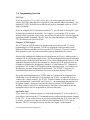
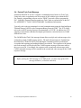
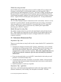
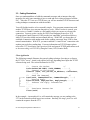
PLC Interface Timing
The 2572 and the PLC exchange requests and data via a shared RAM interface on the
module. Access to the shared RAM is determined by the PLC scan cycle. Requests from
the 2572 must be loaded prior to the beginning of a PLC scan. Replies are written to the
shared RAM by the PLC at the end of the PLC scan.
CTI 2572 Programming Reference Manual V2.1
35
50 ms
50 ms
SCAN 1
SCAN 2
2572 Request
PLC Reply
Since the timing of the access to the PLC is determined by the PLC scan rate; the longer
the scan time, the less often PLC data can be accessed. The minimum time required to
access the PLC memory is one scan. However, because a request could arrive just after
the PLC scan has started, it could take two scans before a response is returned (see
previous figure). On the average, you should estimate the access time as 1.5 times the
scan interval. Therefore, if the scan time is 50 ms, then the access time would average
75ms.
PLC Data Access Size
The amount of data that can be requested at one time depends upon the PLC
configuration and the method used to request data. The shared RAM interface provides 8
slots; each slot can hold one request to the PLC or reply from the PLC.
When the request is a task code, each task code occupies one slot. Thus, the shared RAM
can accommodate a maximum of 8 task code requests at one time. However, the PLC
may limit task codes per scan to less than 8. Some PLC’s (e.g. SIMATIC® TI525) have
a fixed task code per scan of 2. Most others, including the 545, 555, and TI575, default
to 2 task codes per scan but allow the value to be set to a value up to eight.
When CAMP Memory Transfer commands are used to access the PLC, the 2572 uses a
more efficient block transfer method known as Pseudo DMA (PDMA). Using PDMA,
each slot will access up to four times as much data as a typical task code. The number of
PDMA slots are unaffected by the task code per scan setting.
Block vs. Random Access
Generally, it is more efficient to access a contiguous block of data in the PLC than to
access data randomly. Reading or writing contiguous data significantly increases the
amount of data to be transferred in a single scan. For example, using a random read task
code to access V memory could access as few as seven words of data per task code.
Conversely, a CAMP Memory Read (which uses PDMA) could read as many as 60
words per SFIC slot.
36
CTI 2572 Programming Reference Manual V2.1
TCP/IP Processing Overhead
Each TCP/IP message requires the resources of the PC and the 2572 to compose and
decompose each message, to calculate and evaluate error checking fields, and to
generate network acknowledgments (TCP only). The actual overhead will depend upon
the speed of the PC, the protocol used (TCP typically requires an additional 10 ms for
acknowledgment) and the condition of the network (noisy networks can require multiple
retries). Typical TCP/IP overhead (query and response) is 30 - 40 ms per transaction.
Module Input Queue Depth
The 2572 allows multiple clients to communicate with it concurrently. However, access
to the PLC is gated by the PLC interface described in previous sections. In situations
where the requests arrive faster than the PLC can process them, the 2572 queues the
requests. The response time to a request will vary with the queue depth and the
processing rate of the PLC interface.
Module Message Processing Time
The module consumes about 1ms per task code unpacking the task code data from the
PLC. Other module processing tasks may also consume several milliseconds at times.
Some of the module processing time may be overlapped with the PLC and/or host
computer operations.
3.2. Performance Enhancement Tips
Performance Tips - PLC
There are several actions you may be able to take to ensure that the PLC is optimized for
performance.
•
Group data in contiguous locations in PLC memory, which allows you to use block
commands to access large groups of data. The PLC logic provides a means to copy
data and also allows discrete values to be packed into V memory words. These
commands add very little to the PLC scan time. This action, coupled with the use of
CAMP memory transfer commands, offers the largest potential for performance
enhancement.
•
If you are using task codes to access the PLC, ensure that the “task codes per scan”
parameter is set to the maximum value.
•
Avoid using fixed scan times, if possible. For most PLC models, a fixed scan time
could cause task code processing to be deferred until a later scan or could result in
unnecessary idle time.
Install the module in a local base, if possible.
•
Performance Tips - Application
Supervisory control and monitoring applications usually read a large number of data
elements continuously, while writing a few data points occasionally. With this
CTI 2572 Programming Reference Manual V2.1
37
transaction mix, several request messages may be required to obtain all of the data
required by the application at each point in time.
A primary means of optimizing total throughput is to minimize the number of messages
required to obtain the data by maximizing the amount of data requested in each message.
This strategy minimizes the TCP/IP processing overhead and allows 2572 to access more
data per scan, potentially reducing the number of scans required to obtain the data.
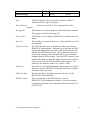
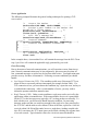
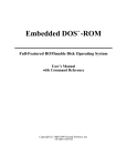
Data Blocking
One means to accomplish the above is to request large block of data rather than reading
random points. If the requested data is already in a single block in the PLC, then this task
is rather easy. However, if the data is spread out thorough PLC memory, your
application may need to combine the data requests into a large block read. When the data
is returned, your application would then pick out the actual data needed and ignore the
rest.
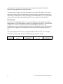
The example below indicates how an application the needed V10-V20, V51-V68, and
V74-V80 could obtain the data in one CAMP memory read of 81 words.
V10 - V20
(required)
38
V21 - V50
(unused)
V51-V68
(required)
V69 - V73
(unused)
V74 - V 80
(required)
CTI 2572 Programming Reference Manual V2.1
CAMP Memory Transfer vs. Packed Task Code
For applications where the data can be retrieved by large block reads, using the CAMP
memory transfer will result in the most efficient data transfer. Note that, in one CAMP
read, you could return up to 256 words which could include 4096 discrete points.
However, since CAMP memory transfer allows only one data type per message,
applications which read small blocks many different data types may benefit from using
the Packed Task Code format. For example, to read 10 V memory values, 10 control
relays, 30 WX values, and 2 loop process variables would require 4 messages (one for the
V, one for the C, one for the WX, and one for the loop). Using the packed task code
format (which lets you place up to 14 NITP task code requests in a single message), you
could obtain the data in a single message.
If you need to write more than a few random values should use the Packed Task Code
format. The CAMP memory transfer format allows only one memory range per message.
Multiple Command / Reply Sessions
Another way to improve overall performance is to establish more than one command
reply session with the same 2572. Implemented properly, the overlapped processing that
occurs between the PC, 2572, and PLC can enhance total throughput.
The best way to accomplish this task is to open a second socket to the module, treating
each socket as a separate command / reply stream. Start by sending a request to each
socket. When you receive a reply on one of the sockets, process the response and send
the next request in the queue to that socket. Continue until all messages have been sent
and replies have been processed. This technique has several advantages over other
approaches:
• It continues to use the same command/response protocol as a single socket (including
message ID sequence)
• Your application can use the socket source to match response messages to the
corresponding command message rather than requiring complex logic to accomplish
this.
• If your application throughput requirements did require a second 2572 in the same
PLC rack, it would be easy to transition to this configuration by simply changing the
IP address of the second socket.
• If you use UDP no additional resources are required at the module.
You should exercise care in how you use this technique. In particular:
• Opening more than two sockets to the 2572 will probably not result in significant
additional performance improvement.
• Opening a TCP socket to the module will cause the module to allocate resources for
the TCP socket. Each 2572 has a limited number of TCP sockets that can be
allocated. See the 2572 Installation and Operations Guide.
CTI 2572 Programming Reference Manual V2.1
39
•
40
If multiple PCs, each using this technique, are accessing the same 2572 concurrently,
overall system performance could actually decline, especially if the applications are
requesting data faster than actually required.
CTI 2572 Programming Reference Manual V2.1
3.3. Coding Illustrations
Once you understand how to build the command messages and to interpret the reply
messages, the only issue remaining is how to send and receive these messages from the
PLC. Since the 2572 acts as a TCP/IP host, you will use standard TCP/IP structures and
coding techniques communicate with the module.
You will find the interface to be reasonably simple. Your program communicates with
another TCP/IP host via a structure known as a socket. When a socket is created, your
code receives a “handle” (similar to a file handle) which you can use to reference the
connection. You may create a socket for UDP (User Datagram Protocol) or TCP
(Transmission Control Protocol). UDP provides an “unreliable” packet based delivery
while TCP provides reliable stream oriented delivery. With UDP, you do not have to
establish a connection with another node before sending a message; thus, UDP is often
termed connectionless. With TCP, you must establish a “virtual circuit” connection with
another process before sending data. For more information on TCP/IP features please
refer to the 2572 Installation and Operation Guide and general TCP/IP publications such
as Internetworking with TCP/IP by Douglas Comer (1991, Prentice Hall).
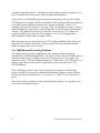
Client Application
The following example illustrates the general coding technique for acting as a client to
the 2572 PLC server. Actual code required will vary depending based upon the TCP/IP
software being used. The socket illustrated is for TCP.
L
o
o
p
/*
Create the Socket
*/
sock=Socket(AF-INET, SOCK_STREAM, ......)
/*
Connect to the Server
*/
Connect (sock, PLC_Server_IP_Address, ServerPort,
.....)
/*
Send the Command
*/
send(sock, CommandBuffer, CommandLength, ....)
//
Receive Reply
receive(sock, ReplyBuffer, ReplyLength,....)
//
Process the reply information
......
.....
/*
Terminate Connection
*/
Close(sock)
In the example, CommandBuffer will contain the message you are sending to the
2572 in the format described in previous sections. Similarly, the ReplyBuffer will
contain the response from the 2572.
CTI 2572 Programming Reference Manual V2.1
41
Server Application
The following example illustrates the general coding techniques for opening a TCP
server socket.
L
o
o
p
/*
Create the Socket
*/
sock=socket(AF-INET, SOCK-STREAM, .......)
/*
Assign a port number to the socket and
establish a listen queue
*/
bindr=bind(sock, SocketNumber....)
listen(sock, QueueSize....)
/*
Wait for a connection
*/
consock=accept(sock,ClientAddress...)
/*
Process Command
*/
receive(consock, CommandBuffer, CommandLen,....)
/*
Process the command information
*/
.....
......
......
send(consock, ReplyBuffer, ReplyLen,...)
/*
Terminate Connection
*/
close sock
In the example above, CommandBuffer will contain the message from the PLC Client.
ReplyBuffer will contain the applicable reply generated by your code.
Error Processing
Due to the nature of network communications, you will experience errors from time to
time. Network communications may be lost temporarily, processors may be taken off
line, command messages or replies may be lost from time to time. You application must
provide recovery for these circumstances. Following are some conditions you should
handle.
•
Lost Network Connection (TCP). This condition could occur if the target 2572 was
taken off-line or a network path was interrupted (for example, broken cable). If a
TCP connection is lost, you must detect the condition, log / report the error, and try to
re-establish the connection. After a certain number of retries, you may wish to
inform the operator and allow manual restart.
•
Reply Timeout (UDP). Under certain conditions a reply may not be received by the
application within a reasonable time. With connectionless services it is permissible
for the 2572 or the host processor (typically a PC) to drop packets occasionally. To
deal with this case, you will need to handle timeout conditions. In processing
timeouts, make sure that you wait long enough for the reply to be sent, processed by
the 2572/PLC and the answer to be returned. Most of the time, replies on a LAN are
received within 100-200 milliseconds; however, under heavy loading coupled with
slow PLC scan times, the 2572 input queue can be filled, resulting in a response time
of several seconds. Typical timeout values for a local area network should be
42
CTI 2572 Programming Reference Manual V2.1
approximately 4 seconds. This value should be increased if you are communicating
over a wide area network (WAN).
•
Message ID Matching. Your application should check that the message ID in the
reply matches the ID in the request. It is possible for replies to arrive out of sequence
or after you have declared a timeout. If you receive a reply with an ID that does not
match an outstanding request, you should ignore the reply and log an error in your
application.
•
2572 Queue Full Messages. When the maximum number of messages are contained
in a 2572 queue, the module will reject the request and return an error message to the
requester. You could use this as a signal to reduce your polling rate, assuming other
client applications communicating with the same module also cooperate.
•
Other CAMP Error Messages. See Appendix A for errors that can be returned.
Many of these errors result from errors in coding the application. You can use these
to debug your code. Others may result from operator entry errors, PLC configuration
errors, etc. Obviously you should report these errors to the operator.
•
Event Logging. It is very useful to log certain events that may occur during
processing. In particular you may wish to log errors. Many developers allow logging
thresholds to be set, so that the logger can be used to analyze and debug the
application as well as to track errors.
•
3.4. Development and Debugging Tools
To develop the application you will need:
• Siemens® SIMATIC® 505 PLC, rack, and power supply,
• CTI 2572 Ethernet TCP/IP Adapter,
• Siemens® SIMATIC® TISOFT PLC programming software or equivalent,
• Ethernet Network (typically a hub, PC adapter, and cabling),
• Appropriate application programming software (editor, compiler, etc.),
• TCP/IP software and reference documentation.
In addition, it is highly recommended that you acquire a network analysis software
package. One such package is Etherprobe by General Software (Redmond WA).
Etherprobe allows you to capture packets sent to and from your host(s) and the 2572
module(s). Once captured, you can analyze the packets for contents to verify the CAMP
commands that are actually being sent and received on the network. You can also use the
packet timestamps to evaluate PC processing and 2572/PLC response times. Many
developers have found this analysis software to be an invaluable debugging tool.
3.5. TCP/IP Problems
If you cannot communicate with a 2572 on the network, ensure that the PLC rack is
powered, that the network parameters (including the IP address) are set, that the module
CTI 2572 Programming Reference Manual V2.1
43
is properly logged into the PLC, and that the network cabling is properly connected. See
the 2572 Installation and Operation Guide for additional information .
After you have verified that the physical network is functioning, you can check out the
TCP/IP protocol by sending a PING to the module. PING sends an ICMP echo request to
a specified network address to determine if the address is reachable. If the 2572 is
reachable at the specified address, it will reply. If the 2572 module does reply, you know
that the IP address you specified is correct and that the TCP/IP firmware in the module is
working. If the module does not reply to the PING, check that the 2572 address is set
properly and that you are using the correct address. See your TCP/IP application
documentation for information on sending a PING.
Make sure that you have specified the correct TCP/UDP port number for the PLC server
on both the PLC and the client code. If you are using TCP, ensure that the maximum
number of connections is not exceeded.
3.6. CAMP Message Processing Problems
The CAMP protocol provides comprehensive error reporting which should help
considerably in troubleshooting problems. By design, a server using the CAMP protocol
will reply to any message it detects except Type F (error) message. See Chapter 3 for
details on CAMP. If you are sending messages to a CAMP server via TCP/IP and are not
getting a reply, then you may not have established a socket associated with it. See
TCP/IP Problems.
If the CAMP server replies with a Type F message, this means the CAMP message
packet is invalid. Be sure you have included both message delimiters, used a valid type,
and have properly computed the BCC. See Section 2.2. CAMP Protocol Description,
page 9.
Other errors indicate a problem in processing the message request. See Appendix A for
error codes and possible solutions.
44
CTI 2572 Programming Reference Manual V2.1
APPENDIX A. 2572 ERROR CODES
This Appendix provides a description of the error codes that may be returned by the 2572
in a response message and offers potential solutions to the error conditions.
CAMP Error Codes
This section describes the error codes that may be returned by the CAMP protocol. The
error code is located in word 3 of the error message. See Command Error Response on
page 23.
HEX
DESCRIPTION
SOLUTION
006E
NITP PROTOCOL ERROR
Although this error could result from a network
error, the most likely problem is an error in
building the message. Check your coding.
This error may occur when sending Packed Task
Code messages. An NITP protocol error is
defined as:
checksum did not match computed checksum
For the Packed Task Code Format, Error Word 4
will contain the message number of the Task Code
message where the error was detected. The
message number is in Hex ASCII format (e.g.
message number 14 is shown as 000E).
BAD OR MISSING DELIMITER
The remote device detected a missing delimiter
in the message
This error could result from a transient error in the
data link. Application logic should retry the
command.
odd number of characters received,
character other than 0-9 or A-F received,
0073
If the problem persists, you are most likely
creating the CAMP message incorrectly. Make
coding changes as required.
0074
BAD BLOCK CHECK CHARACTER
The remote device found the block check
character to be bad.
See error code 0073.
0075
INVALID TYPE
The remote device detected an invalid TYPE
character in the message.
See error code 0073.
0076
INVALID DATA CHARACTER
See error code 0073.
The remote device detected an invalid data
character in the message sent from the remote
device. Only characters 0-9 and A-F are
allowed.
CTI 2572 Programming Reference Manual V2.1
45
HEX
DESCRIPTION
SOLUTION
0077
ODD NUMBER OF CHARACTERS
The remote device detected an odd number of
characters in the message. All CAMP messages
have an even number of characters.
See error code 0073.
0078
INVALID DEVICE CODE
See error code 0073.
0080
The remote device detected an invalid device
code in the message
INVALID ERROR CHARACTER
The message contained an unknown error
character.
0081
NO WORDS TO WRITE
The message type indicated data was to be
written but the message did not contain any
words to write.
0082
INVALID WORD COUNT
The word count field does not match the actual
number of data words.
0083
MEMORY ADDRESS = 0
The memory address contained in the read or
write message was 0. This is not a valid
memory address.
0084
WRITE UNSUCCESSFUL
The remote device was unable to write the
number of words you requested
Review your error processing logic. Make sure
you are returning a valid error code.
You must include at least one word of data to be
written. Change your application as required.
Ensure that the word count matches the actual
number of words you are sending.
Your software is generating an invalid memory
address. CAMP memory addresses are 1 relative.
Review the code that creates the message and
make corrections.
The error may occur if the number of words
specified causes the memory boundary to be
exceeded while reading memory. If so, correct
either the number of words requested or the
starting memory address.
This may also indicate a remote device error.
Retry, if the problem persists, check the remote
device.
0085
INVALID COMMAND CODE
Correct the request and retry.
The message contained an command code not
supported by the remote device.
008F
INVALID NUMBER OF WORDS
Correct the request and retry.
You specified a value of 0 for the number of
words to write.
0090
46
UNSUPPORTED ADDRESS CLASS OR
DEVICE CLASS
Examine the value contained in the address/device
class field for errors. Correct as necessary.
You specified an address class or device that is
not supported by the remote device.
Check the version of the module firmware.
Versions earlier than 5.0 do not support an address
class value other than 0000.
CTI 2572 Programming Reference Manual V2.1
HEX
DESCRIPTION
SOLUTION
0091
REQUEST TOO LARGE
Correct the request and retry.
You tried to read more than 256 words.
0093
CAMP MAXIMUM RESPONSE SIZE
EXCEEDED
Correct the request and retry.
You have asked for more data via a Packed Task
Code request than can be returned in a CAMP
response message.
0094
MAXIMUM NUMBER OF TASK CODES
PER MESSAGE EXCEEDED
Correct the request and retry.
You included more than 14 Task Codes in the
Packed Task Code request message.
0095
INVALID TASK CODE CHARACTER
COUNT
Correct the request and retry.
The NITP character count is outside the range of
valid values or the count exceeds the number of
characters remaining in the message.
00AC
MEMORY READ ERROR
The remote device could not execute the
command to read data.
This error may occur because you are specifying a
starting memory address that is not valid for the
remote device. If so, correct the memory address.
The error may occur if the number of words
specified causes the memory boundary to be
exceeded while reading memory. If so, correct
either the number of words requested or the
starting memory address.
This error may be encountered if you specify an
odd number word count when using address
classes which access real numbers. Set the word
count to an even number, if in error.
Some address classes require data to be accessed in
multiple words. See Appendix B. This error may
be encountered if you do not specify the correct
multiple in the word count
This error may occur due to a problem with the
remote device. Retry the command message. If
the problem persists, check the remote device.
CTI 2572 Programming Reference Manual V2.1
47
HEX
DESCRIPTION
SOLUTION
00AD
MEMORY WRITE ERROR
This error may occur because you are specifying a
starting memory address that is not valid for the
remote device. If so, correct the memory address.
The remote device could not execute the
command to write memory.
The error may occur if the number of words
specified causes the memory boundary to be
exceeded while writing memory. If so, correct
either the number of words requested or the
starting memory address.
This error may occur due to a problem with the
remote device. Retry the command message. If
the problem persists, check the remote device.
00C7
MESSAGE QUEUE FULL
Re-Send the request.
The message was rejected by the module
because an input queue contained the maximum
number of entries.
If the problem persists, you must correct the
system problem that is causing the module
overload. Check the following:
The module is receiving requests faster than
they can be processed by the PLC.
PLC Configuration: Make sure the task codes per
scan are set to 8. Check the scan time setting; a
large fixed scan time will degrade communications
performance on most PLC models. For best
communications performance in most situations,
set the scan to variable.
The high byte of data word 4 in the error
message will identify the queue.
01 = Packed Task Code Queue
02 = PLC Processing Queue
The low byte of data word 4 will indicate the
maximum entries for the queue.
Application: You may be inadvertently sending
new requests before waiting an reasonable time for
a response. If sustained, over time this action can
fill up the queue. Correct as necessary.
Other: If multiple PCs are continuously polling a
single 2572, you may need to slow the poll rate.
Alternately, you may need to install an additional
2572 in the PLC rack and split transactions among
them.
48
CTI 2572 Programming Reference Manual V2.1
NITP Task Code 00 Error Codes
This group of error codes is returned by the remote PLC when an error is encountered
processing a task code. The error code is returned in a message which contains a task
code 00, followed by the specific error code. The error codes are summarized below for
your reference. Many of these errors apply to programming task codes or special
function routines. Common errors which you may encounter are shown in italics.
SIMATIC® 505 Task Code 00 Error Listing
HEX
01
02
03
04
05
06
07
08
09
0A
0B
0C
0D
0E
0F
10
11
12
13
14
15
16
17
18
19
1A
1B
1C
1D
1E
21
22
3F
DESCRIPTION
Reset Current Transaction
Address out of Range (Other than Ladder Logic)
Requested Data not Found
Illegal Task Code Request (e.g. Task Code not Supported)
Request Exceeds Program Memory Size (Ladder Logic)
Diagnostic Fail upon Power Up
Fatal Error Detected
Keylock Protect Error
Incorrect amount of Data sent with Request
Illegal Request in Current Operational Mode
Network was not Deleted
Attempted Write Operation Did Not Verify
Illegal Number of ASCII Characters Received
Illegal Write to Program Memory (Non Volatile)
Data not Inserted
Data not Written
Invalid Data sent with the Command
Invalid Operation with NIM (Obsolete)
The store and forward buffer is busy
No response from the Special Function Module
Illegal Instruction found in program memory on a Program to Run transition
Attempted Write to a Protected Variable (e.g. TCC, TCP)
No response from PLC (e.g. Single Scan not performed)
Requested memory size exceeds total available memory
Requested Memory size is not a multiple of block allocation size
Requested memory size is less than minimum defined value.
Requested memory size is larger than maximum defined value
PLC Busy - Cannot complete the requested operation
Comm error in HOLD mode - Transition to Run not allowed
Port Lockout is Active (ref task Code 48)
I/O Configuration Error - too many points
I/O Configuration Conflict
Bus Error Detected
CTI 2572 Programming Reference Manual V2.1
49
40
41
42
43
44
46
47
48
49
4A
4B
4C
4D
4E
4F
50
51
52
53
54
55
56
57
58
59
5A
5B
5C
5D
5E
5F
60
61
50
Operating System Error Detected
Invalid Control Block Type
Control Block Number out of range
Control Block does not exist
Control Block already exists
Offset out of range.
Arithmetic error detected while writing loop or analog alarm parameters
Invalid SF Program type
Instruction number or RAMP/SOAK Step number out of range
Attempt to access an integer only variable as a real.
Attempt to access a real -only value as an integer.
Task Code buffer overflow -- too much data requested
Control Block size error. (Maximum = 32767 bytes)
Attempt to write a read only variable.
Invalid variable type for this operation
Task code request buffer too large (PLC internal error)
Invalid SF Statement size specified
Invalid return value
Attempt to execute a Cyclic statement in a non-cyclic SF program
Control Block is disabled
Control Block is not disabled
Attempt to perform a FTSR-OUT Statement on an empty FIFO
Attempt to perform a FTSR-IN Statement on a full FIFO
Stack overflow while evaluating a MAATH, IF-THEN, or IMATH expression
Maximum SF Subroutine nesting level exceeded (Max depth = 4)
Arithmetic Overflow
Invalid Operator in an IF, MATH, or IMATH expression
S Memory Overflow
Attempt to divide by 0 (IMATH Statement)
FIFO is incompatible with FTSR-IN or FTSR-OUT statement
FIFO is invalid
Invalid Data Type code (Usually MATH, IMATH, or IF-THEN statement)
RAMP/SOAK step type mismatch. Error is logged by Task Code 6 (Write
RAMP/SOAK step) if the fields are being updated and the step type indicated but
the task code does not match the step type of the step being modified.
CTI 2572 Programming Reference Manual V2.1
APPENDIX B. ADDRESS CLASS INFORMATION
General Information
The CAMP Memory Transfer commands contain a field designated as ADDRESS CLASS.
Version 5.0 and later of the 2572 firmware allows you to use the ADDRESS CLASS field to
access data types other than V memory. The high byte of the ADDRESS CLASS
corresponds to the Siemens® SIMATIC® 505 data types as shown in the tables below.
The tables indicate the format of the returned information and whether the variable can
be read and written (r/w) or read only.
Carefully read the notes that apply to certain variable types.
Accessing Real Numbers and 32 Bit Variables
Real numbers and 32 bit fields require two words data words in a CAMP message. When
accessing real numbers or 32 bit fields, you must specify a WORD COUNT which
represents the actual number of data words which will be contained in the CAMP
message. For example, to retrieve a single Loop Process Variable (Type 25), the WORD
COUNT would be set to 2 because a single real number will return two data words.
Common Data Types
Type
00
01
02
06
07
08
09
0A
0E
0F
10
11
12
1A
1B
Variables
CAMP DEFAULT
V Memory
K Memory
Discrete Input Packed
Discrete Output Packed
Control Register Packed
Word Input
Word Output
Timer/Counter Preset
Timer/Counter Current
Drum Step Preset
Drum Step Current
Drum Count Preset
System Status Word
Drum Current Count
CTI 2572 Programming Reference Manual V2.1
Name
V
V
K
X
Y
C
WX
WY
TCP
TCC
DSP
DSC
DCP
STW
DCC
Fmt
Integer
Integer
Integer
16 bits
16 bits
16 bits
Integer
Integer
Integer
Integer
Integer
Integer
Integer
16bit
32bit
Access
r/w
r/w (1)
r/w (1)
r/w (2)
r/w (2)
r/w (2)
r/w
r/w
r/w
r/w
r/w
r/w
r/w (3)
read (4)
read
51
(1) Type 01 and 02 may be used to read memory addresses beyond 65535. The lower
byte of the Address Class is combined with the Address field to yield a 24 bit address.
For example, to access Type 01 (V Memory) location 73245 (0x 011E1D):
The ADDRESS CLASS field would contain - 0101
The ADDRESS field would contain 1E1D
(2) These data types are accessed as a group of 16 bits. When using CAMP Memory
Transfer to write discrete values, you must write them 16 bits at a time. If you wish to
write bits in smaller increments, you must use the applicable task code instead.
The first value accessed will be stored in the least significant bit of the word, with each
successive bit stored in the next higher bit position. For example, if you read two words
of type 08 (control relay) starting at 10, the result returned would be as follows:
WORD 1
Position
Element
1
C25
2
C24
3
C23
4
C22
5
C21
6
C20
7
C19
8
C18
9
C17
10
C16
11
C15
12
C14
13
C13
14
C12
15
C11
16
C10
2
C40
3
C39
4
C38
5
C37
6
C36
7
C35
8
C34
9
C33
10
C32
11
C31
12
C30
13
C29
14
C28
15
C27
16
C26
WORD 2
Position
Element
1
C41
(3) Type 12 can read and write only event drums, not standard drums. This variable
must be accessed in groups of 16 words, one word for each drum step.
(4) The System Status Word can only be read using this data type. However, the
applicable task code may be used to write data to applicable Status Words.
52
CTI 2572 Programming Reference Manual V2.1
Loop Data Types
TT
20
21
22
23
24
25
26
27
28
29
2A
2B
2C
2D
2E
2F
30
31
32
33
34
35
36
37
38
39
3A
3B
3C
3D
3E
3F
40
41
42
48
49
4A
4B
4C
4D
4E
4F
Loop Variables
Loop Gain
Loop Reset Time (min)
Loop Rate Time (min)
Loop High Alarm Limit
Loop Low Alarm Limit
Loop Process Variable
Loop PV High Limit
Loop PV Low Limit
Loop Orange Dev Alarm Limit
Loop Yellow Dev Alarm Limit
Loop Sample Rate (sec)
Loop Setpoint
Loop Output (%)
Loop Status (V) Flags
Loop Control (C) Flags
Loop Ramp/Soak Status Flags
Loop Error
Loop Bias
Loop High-High Alarm Limit
Loop Low-Low Alarm Limit
Loop Rate of Change Alarm Limit
Loop Setpoint High Limit
Loop Setpoint Low Limit
Loop Alarm Deadband
Loop Raw High Alarm Limit
Loop Raw Low Alarm Limit
Loop Raw Process Variable
Loop Raw Orange Dev Alarm Limit
Loop Raw Yellow Dev Alarm Limit
Loop Raw Output
Loop Raw Setpoint
Loop Raw Error
Loop Raw High-High Alarm Limit
Loop Raw Low-Low Alarm Limit
Loop Raw Alarm Deadband
Loop Raw Bias
Loop Raw Setpoint Low Limit
Loop Raw Setpoint High Limit
Loop C Flags - MSW
Loop C Flags - LSW
Loop Derivative Gain Limiting Coef.
Loop Ramp/Soak Step Number
Loop Alarm Ack Flags
CTI 2572 Programming Reference Manual V2.1
Name
LKC
LTI
LTD
LHA
LLA
LPV
LPVH
LPVL
LODA
LYDA
LTS
LSP
LMN
LVF
LCF
LRSF
LERR
LMX
LHHA
LLLA
LRCA
LSPH
LSPL
LADB
LHAR
LLAR
LPVR
LODAR
LYDAR
LMNR
LSPR
LERRR
LHHAR
LLLAR
LADBR
LMXR
LSPLR
LSPHR
LCFH
LCFL
LKD
LRSN
LACK
Fmt
Real
Real
Real
Real
Real
Real
Real
Real
Real
Real
Real
Real
Real
16 bits
32bit
16 bits
Real
Real
Real
Real
Real
Real
Real
Real
Integer
Integer
Integer
Integer
Integer
Integer
Integer
Integer
Integer
Integer
Integer
Integer
Integer
Integer
Integer
Integer
Real
Integer
Integer
Access
r/w
r/w
r/w
r/w (1)
r/w (1)
r/w
r/w (2)
r/w (2)
r/w (1)
r/w (1)
r/w
r/w
r/w
read (3)
r/w
read (3)
read
r/w
r/w (1)
r/w (1)
r/w
r/w (1)
r/w (1)
r/w
r/w (1)
r/w (1)
r/w (4)
r/w (1)
r/w (1)
r/w
r/w
read
r/w (1)
r/w (1)
r/w
r/w
r/w (1)
r/w (1)
r/w
r/w
r/w
r/w
read (3)
53
(1) When writing these values, you must ensure the limits do not overlap. No checking is
performed. For example, you can set the Loop Low Alarm limit (LLA) higher than the
Loop High Alarm limit (LHA). However, if you attempt to set the values beyond the
process variable limits (LPVL and LPVH), the value will clamp to the nearest endpoint
of the range. Similarly, if a process variable limit is changed so that this variable is
outside the limit, the variable will be clamped to the nearest endpoint of the range.
(2) Setting the LPVH value lower than the current LPVL will cause the LPVL to clamp
to the new LPVH value. Similarly setting the LPVL value higher than current LPVH
value will cause the LPVH to clamp to the new LPVL value.
(3) These flags cannot be written using this data type. However, the enable and
acknowledge bits may be written using task codes.
Alarm Data Types
TT
50
51
52
53
54
55
56
57
58
59
5A
5B
5C
5D
5E
5F
60
61
62
63
64
65
66
67
68
69
6A
6B
6F
54
Analog Alarm Variables
Alarm High Alarm Limit
Alarm Low Alarm Limit
Alarm Process Variable
Alarm PV High Limit
Alarm PV Low Limit
Alarm Orange Dev Alarm limit
Alarm Yellow Dev Alarm Limit
Alarm Sample Rate (sec)
Alarm Setpoint
Alarm V Flags
Alarm C Flags
Alarm Error
Alarm High-High Alarm Limit
Alarm Low-Low Alarm Limit
Alarm Rate of Change Alarm Limit
Alarm Setpoint High Limit
Alarm Setpoint Low Limit
Alarm Alarm Deadband
Alarm Raw High Alarm Limit
Alarm Raw Low Alarm Limit
Alarm Raw Process Variable
Alarm Raw Orange Deviation
Alarm Raw Yellow Alarm Limit
Alarm Raw Setpoint
Alarm Raw Alarm Deadband
Alarm Raw Error
Alarm
Alarm Raw Low-Low Alarm Limit
Alarm Raw Setpoint Low Limit
Name
AHA
ALA
APV
APVH
APVL
AODA
AYDA
ATS
ASP
AVF
ACF
AERR
AHHA
ALLA
ARCA
ASPH
ASPL
AADB
AHAR
ALAR
APVR
AODAR
AYDAR
ASPR
ADBR
AERRR
AHHAR
ALLAR
ASPLR
Fmt
Real
Real
Real
Real
Real
Real
Real
Real
Real
Integer
Real
Real
Real
Real
Real
Real
Real
Real
Integer
Integer
Integer
Integer
Integer
Integer
Integer
Integer
Integer
Integer
Integer
Access
r/w (1)
r/w (1)
r/w
r/w (2)
r/w (2)
r/w
r/w
r/w
r/w
read (3)
r/w
read
r/w (1)
r/w (1)
r/w
r/w (1)
r/w (1)
r/w
r/w (1)
r/w (1)
r/w
r/w
r/w
r/w
r/w
read
r/w
r/w (1)
r/w (1)
CTI 2572 Programming Reference Manual V2.1
70
Alarm Raw Setpoint High Limit
CTI 2572 Programming Reference Manual V2.1
ASPHR
Integer
r/w (1)
55
TT
71
72
73
Analog Alarm Variables (Continued)
Alarm MSW Alarm C Flag
Alarm LSW Alarm C Flags
Analog Alarm - Alarm Ack Flag
Name
ACFH
ACFL
AACK
Fmt
Integer
Integer
Integer
Access
r/w
r/w
read (3)
(1) When writing these values, you must ensure the limits do not overlap. No checking is
performed. For example, you can set the Analog Low Alarm limit (ALA) higher than the
Analog High Alarm limit (AHA). However, if you attempt to set the values beyond the
process variable limits (APVL and APVH), the value will clamp to the nearest endpoint
of the range. Similarly, if a process variable limit is changed so that this variable is
outside the limit, the variable will be clamped to the nearest endpoint of the range.
(2) Setting the APVH value lower than the current APVL will cause the APVL to bet set
to the new APVH value. Similarly setting the APVL value higher than current APVH
value will cause the APVH to be set to the new APVL value.
(3) These flags cannot be written using this data type. However, the enable and
acknowledge bits may be written using task codes.
56
CTI 2572 Programming Reference Manual V2.1
APPENDIX C. TASK CODE OVERVIEW
Devices which communicate with Siemens® SIMATIC® 505 PLCs use task codes to
read and write data in the PLC. This Appendix provides a brief summary of task codes
and the NITP protocol. The task codes typically used for supervisory control and
monitoring applications are described in detail in several Siemens® publications.
NOTE:
Before implementing an application using the task codes, you should obtain a publication
such as the SIMATIC® TI575 Task Code User Manual, Order # PPX:575-8104-1.
The 2572 uses a variation of the Siemens® SIMATIC® Non-Intelligent Terminal
Protocol (NITP) for task code access. NITP is an ASCII protocol with the following
format.
Start Delimiter
:
Character
Count
Message
Body
Error Check
Code
End Delimiter
;
Both command and response messages start with a colon (ASCII 3A) and end with a
semicolon (ASCII 3B). All data is represented as the ASCII equivalent of the
hexadecimal representation. For example, the decimal number 58 is expressed as the
characters 3A (hex 33 41). The character count is a simple count of all characters in the
message, including the beginning and end delimiters. The maximum message length of a
single message is 72 characters
NOTE: The CAMP implementation omits the beginning and ending delimiters, but keeps
the same character count.
The message body consists of the task code and related parameters and data. Commonly
used task codes include:
01
02
50
51
5A
Read Word Memory Random
Write Word Memory Random
Read User Word Area Block
Write User Word Area Block
Write Block
CTI 2572 Programming Reference Manual V2.1
57
7E
7F
Read Random
Read Block
Word Codes
The types of data that can be accessed using these task codes closely match the data
element types listed in Appendix B. However, rather than using the data element type
and address, the type and address of the data to be accessed are bit encoded into a
structure known as a word code. Word codes may consist of 1 or two words, depending
upon the data type and address being accessed.
Word codes are classified into three categories:
• Category 1 word codes access variables common to all PLC models (such as V, WX,
DCC).
• Category 2 word codes access loop and alarm variables plus a few special types.
• Category 3 word codes allow configuration of the 545, 555, and TI575 timelime.
If you are communicating with a newer PLC (545, 555, or TI575), you may use any word
code with the above task codes. For example task code 01 or 7E can be used to randomly
read V-memory or loop/alarm variables. Similarly, Task code 50 or 7F can be used to
block read V-memory or loop/alarm variables.
If you are communicating with a 565 PLC, you will find that you cannot use Task Code
01 to read the Category 2 variables (you must use 7E). Also, you cannot use Task Code
02 to write Category 2 variables. There is no equivalent loop random write, only a block
write (5A). If you want to access a TI525 or TI535 PLC, these do not support loops and
also use a different addressing scheme (absolute addressing).
As a practical matter, most installations using the 2572 will be a 545, 555, or TI575. You
may, however, find some TI565 PLCs still used in “hot backup” applications. If you
don’t care about supporting the TI565 PLCs, it is probably easiest to use task code 01 and
02 for all random access.
There are a few relevant task codes that use the data element types rather than word
codes. See appendix B for the data element types. They are:
59
6B
9D
9E
Write Discrete I/O Status by Data Element Type
Read Discrete I/O Status by Data Element Type
Read Random Block via Data Element Type and Offset
Write Random Block via Data Element Type and Offset
Task code 59 and 6B are supported by all 545, 555, TI565, and TI575 PLCs. This is a
very useful task code because it reads and writes discrete data in a packed format.
58
CTI 2572 Programming Reference Manual V2.1
Task Codes 9D and 9E are useful because they can read any data type but avoid the
complexity of calculating word codes. They also let you request several blocks of
different data types in the same task code. However, Task code 9D and 9E are supported
by only later models/ firmware revisions of the SIMATIC® PLCs including: 545-1102
Release 3.0, 555 Release 3.0, and TI 575 Release 3.0. The 545-1101, a commonly
installed PLC, does not support task code 9D or 9E. Thus, use task codes 9D and 9E
only if you don’t need to support the 545-1101 or older PLC models.
CTI 2572 Programming Reference Manual V2.1
59
APPENDIX D. REFERENCE MATERIAL
TABLE 1. Hex to ASCII Conversion
00
01
02
03
04
05
06
07
08
09
0A
0B
0C
0D
0E
0F
10
11
12
13
14
15
16
17
18
19
1A
1B
1C
1D
1E
1F
NUL
SOH
STX
ETX
EOT
ENQ
ACK
BEL
BS
HT
LF
VT
FF
CR
SO
SI
DLE
DC1
DC2
DC3
DC4
NAK
SYN
ETB
CAN
EM
SUB
ESC
FS
GS
RS
US
20
21
22
23
24
25
26
27
28
29
2A
2B
2C
2D
2E
2F
30
31
32
33
34
35
36
37
38
39
3A
3B
3C
3D
3E
3F
space
!
"
#
$
%
&
'
(
)
*
+
,
.
/
0
1
2
3
4
5
6
7
8
9
:
;
<
=
>
?
CTI 2572 Programming Reference Manual V2.1
40
41
42
43
44
45
46
47
48
49
4A
4B
4C
4D
4E
4F
50
51
52
53
54
55
56
57
58
59
5A
5B
5C
5D
5E
5F
@
A
B
C
D
E
F
G
H
I
J
K
L
M
N
O
P
Q
R
S
T
U
V
W
X
Y
Z
[
\
]
^
_
60
61
62
63
64
65
66
67
68
69
6A
6B
6C
6D
6E
6F
70
71
72
73
74
75
76
77
78
79
7A
7B
7C
7D
7E
7F
`
a
b
c
d
e
f
g
h
i
j
k
l
m
n
o
p
q
r
s
t
u
v
w
x
y
z
{
|
}
~
61
WX / WY Quick Reference
62
CTI 2572 Programming Reference Manual V2.1