1
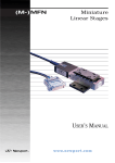
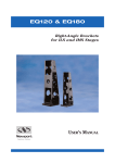
VP-25XL
SP
E
CI
ANTE
NS
AR
ED
GU
High Precision Compact Linear Stage
F I C AT
IO
RoHS
Compliant
USER’S MANUAL
For Motion, Think Newport
VP-25XL
High Precision Compact Linear Stage
Warranty
Newport Corporation warrants this product to be free from defects in
material and workmanship for a period of 1 year from the date of shipment.
If found to be defective during the warranty period, the product will either
be repaired or replaced at Newport’s discretion.
To exercise this warranty, write or call your local Newport representative,
or contact Newport headquarters in Irvine, California. You will be given
prompt assistance and return instructions. Send the instrument, transportation prepaid, to the indicated service facility. Repairs will be made
and the instrument returned, transportation prepaid. Repaired products
are warranted for the balance of the original warranty period, or at least 90
days.
Limitation of Warranty
This warranty does not apply to defects resulting from modification or misuse of any product or part.
CAUTION
Warranty does not apply to damages resulting from:
CAUTION
Please return equipment in
the original (or equivalent)
packing.
You will be responsible for
damage incurred from
inadequate packaging if the
original packaging is not
used.
• Incorrect usage:
– Load on the stage greater than maximum specified load.
– Carriage speed higher than specified speed.
– Improper grounding.
¬ Connectors must be properly secured.
¬ When the load on the stage represents an electrical risk, it must
be connected to ground.
– Excessive or improper cantilever loads.
• Modification of the stage or any part thereof.
This warranty is in lieu of all other warranties, expressed or implied,
including any implied warranty of merchantability or fitness for a particular
use. Newport Corporation shall not be liable for any indirect, special, or
consequential damages.
No part of this manual may be reproduced or copied without the prior written approval of Newport Corporation.
This manual has been provided for information only and product specifications are subject to change without notice. Any changes will be reflected in
future printings.
EDH0204En1020 — 07/11
ii
VP-25XL
High Precision Compact Linear Stage
Table of Contents
Warranty .................................................................................................................ii
EC Declaration of Conformity ...............................................................................v
Definitions and Symbols.......................................................................................vi
Warnings and Cautions ....................................................................................vi
Warnings ...............................................................................................................vii
Cautions ...............................................................................................................viii
1.0
— Introduction .................................................................................1
2.0
— Description ...................................................................................2
2.1 Design Details ............................................................................................2
3.0
3.1
3.2
3.3
3.4
3.5
— Characteristics ............................................................................3
Definitions ..................................................................................................3
Mechanical Specifications........................................................................4
Load Specification Definitions.................................................................4
Load Characteristics and Stiffness .........................................................4
Stage Weights ............................................................................................5
4.0
— Drive ................................................................................................5
5.0
— Motor ...............................................................................................6
5.1
5.2
5.3
5.4
5.5
6.0
DC Motor Characteristics.........................................................................6
Command Signals for UE25CC DC Motor ...............................................6
Sensor Position..........................................................................................6
Feedback Signal Position..........................................................................7
Pinouts........................................................................................................8
— Connection to Newport Controllers ................................9
6.1 Warnings on Controllers ..........................................................................9
6.2 Connection ...............................................................................................10
6.3 Cables .......................................................................................................10
7.0
— Dimensions .................................................................................11
7.1 (M-)VP-25XL Precision Compact Linear Stage.....................................11
7.2 (M-)VP-25XL Stage without Top Plate Interface ..................................11
8.0
— Assemblies ..................................................................................12
8.1 XY Mounting ............................................................................................12
8.2 XYZ Configuration...................................................................................13
iii
EDH0204En1020 — 07/11
VP-25XL
High Precision Compact Linear Stage
9.0
— Maintenance ..............................................................................14
9.1 Maintenance.............................................................................................14
9.2 Repairing ..................................................................................................14
9.3 Calibration................................................................................................14
Service Form ...................................................................................................15
EDH0204En1020 — 07/11
iv
VP-25XL
High Precision Compact Linear Stage
EC Declaration of Conformity
VP-25XL
EC Declaration of Conformity
following Annex II-1A
of Directive 2006/42/EC on machinery
The manufacturer:
MICRO-CONTROLE Spectra-Physics,
1 rue Jules Guesde ZI. Bois de l'Epine - BP189
F-91006 Evry FRANCE
Hereby declares that the machinery:
Description: "VP-25XL"
Function: High Precision Compact Linear Stage
Models: (M-)VP-25XL
– the technical file of which was compiled by:
Mr Dominique DEVIDAL, Quality Director,
MICRO-CONTROLE Spectra-Physics, Zone Industrielle - B.P.29
F-45340 Beaune La Rolande France
– complies with all the relevant provisions of the Directive 2006/42/EC on machinery.
– complies with all the relevant provisions of the Directive 2004/108/EC relating to electromagnetic compatibility.
– was designed and built in accordance with the following harmonised standards:
NF EN 61326-1:2006 « Electrical equipment for measurement, control and
laboratory use – EMC requirements – Part 1: General requirements »
NF EN 55011:2007 Class A
– was designed and built in accordance with the following other standards:
NF EN 61000-4-2
NF EN 61000-4-3
NF EN 61000-4-4
NF EN 61000-4-5
NF EN 61000-4-6
ORIGINAL DECLARATION
Done in Beaune La Rolande on 09 June 2011
Dominique DEVIDAL
Quality Director
v
DC
DC1-EN
1- EN rev:A
r e v:A
EDH0204En1020 — 07/11
VP-25XL
High Precision Compact Linear Stage
Definitions and Symbols
The following terms and symbols are used in this documentation and also
appear on the product where safety-related issues occur.
General Warning or Caution
The exclamation symbol may appear in warning and caution tables in this
document. This symbol designates an area where personal injury or damage
to the equipment is possible.
European Union CE Mark
The presence of the CE Mark on Newport Corporation equipment means
that it has been designed, tested and certified as complying with all
applicable European Union (CE) regulations and recommendations.
ATTENTION
This stage is a Class A device. In a residential environment,
this device can cause radioelectric interferences. In this case,
suitable measurements must be taken by the user of this
device.
0.1
Warnings and Cautions
The following are definitions of the Warnings, Cautions and Notes that may
be used in this manual to call attention to important information regarding
personal safety, safety and preservation of the equipment, or important
tips.
WARNING
Situation has the potential to cause bodily harm or death.
CAUTION
Situation has the potential to cause damage to property or
equipment.
NOTE
Additional information the user or operator should consider.
EDH0204En1020 — 07/11
vi
VP-25XL
High Precision Compact Linear Stage
Warnings
WARNING
The motion of objects of all types carries potential risks for operators.
Ensure the protection of operators by prohibiting access to the dangerous
area and by informing the personnel of the potential risks involved.
WARNING
Do not use this stage when its motor is emitting smoke or is unusually
hot to the touch or is emitting any unusual odor or noise or is in any
other abnormal state.
Stop using the stage immediately, switch off the motor power and then
disconnect the electronics power supply.
After checking that smoke is no longer being emitted contact your
Newport service facility and request repairs. Never attempt to repair the
stage yourself as this can be dangerous.
WARNING
Make sure that this stage is not exposed to moisture and that liquid does
not get into the stage.
Nevertheless, if any liquid has entered the stage, switch off the motor
power and then disconnect the electronics from power supply.
Contact your Newport service facility and request repairs.
WARNING
Do not insert or drop objects into this stage, this may cause an electric
shock, or lock the drive.
Do not use this stage if any foreign objects have entered the stage.
Switch off the motor power and then disconnect the electronics power
supply.
Contact your Newport service facility for repairs.
WARNING
Do not place this stage in unstable locations such as on a wobbly table
or sloping surface, where it may fall or tip over and cause injury.
If this stage has been dropped or the case has been damaged, switch off
the motor power and then disconnect the electronics power supply.
Contact your Newport service facility and request repairs.
WARNING
Do not attempt to modify this stage; this may cause an electric shock or
downgrade its performance.
WARNING
Do not exceed the usable depth indicated on the mounting holes (see
section “Dimensions”). Longer screws can damage the mechanics or
cause a short-circuit.
vii
EDH0204En1020 — 07/11
VP-25XL
High Precision Compact Linear Stage
Cautions
CAUTION
Do not place this stage in a hostile environment such as X-Rays, hard
UV,… or in any vacuum environment.
CAUTION
Do not place this stage in a location affected by dust, oil fumes, steam or
high humidity. This may cause an electric shock.
CAUTION
Do not leave this stage in places subject to extremely high temperatures
or low temperatures. This may cause an electric shock.
• Operating temperature: +10 to +35 °C.
• Storage temperature: -10 to +40 °C (in its original packaging).
CAUTION
Do not move this stage if its motor power is on.
Make sure that the cable to the electronics is disconnected before moving
the stage. Failure to do so may damage the cable and cause an electrical
shock.
CAUTION
Be careful that the stage is not bumped when it is being carried. This may
cause it to malfunction.
CAUTION
When handling this stage, always unplug the equipment from the power
source for safety.
CAUTION
When the carriage is in its end-of-run position, it is strongly
recommended not to go beyond this point by using the manual knob as
this may damage the stage mechanism.
CAUTION
Contact your Newport service facility to request cleaning and
specification control every year.
EDH0204En1020 — 07/11
viii
VP-25XL
High Precision Compact Linear Stage
High Precision Compact Linear Stage
VP-25XL
1.0
Introduction
This manual provides operating instructions for the (M-)VP-25XL precision
compact linear stage.
(M-)VP-25XL translation stage.
RECOMMENDATION
We recommend you read carefully the chapter “Connection to electronics” before using the (M-)VP-25XL stage.
3 stages (M-)VP-25XL in XYZ configuration.
1
EDH0204En1020 — 07/11
VP-25XL
2.0
High Precision Compact Linear Stage
Description
The (M-)VP-25XL stages address multi-axis, high precision positioning
requirements in fiber optics, biomedical, semiconductor, and high precision test and measurement applications. Features including its ultra-compact size and high reliability make them appropriate for device testing,
micro-assembly, micro-machining, and manipulation of small, lightweight
parts such as fiber optical devices, micro-optics, MEMS, cell probes, or
semiconductor devices.
Based on a high precision drive technology including low-friction ball
screw and recirculating ball bearings, the (M-)VP-25XL stages deliver highly
reliable positioning performance at a maximum speed of 25 mm/s.
Compared to alternative direct-drive technologies, the ball screw drive of
the (M-)VP-25XL stages provides greater thrust for higher servo stiffness
and load capacity, higher efficiency resulting in less heat induced position
drift, as well as minimum tuning efforts. Furthermore, the self-locking at
power-off considerably simplifies operational safety.
The modular (M-)VP-25XL stages enable the construction of compact multiaxes positioning systems. For example, by combining three (M-)VP-25XL
stages with the VP-BK bracket, a versatile and compact 3 degrees of motion
system is produced, keeping the height of the horizontal mounting plate as
low as 105 mm (±12.7 mm). For applications requiring up to 6 degrees of
motion, our SR50 and PR50 rotation stages and GON series goniometers
can be easily added to the system. This complete modular approach provides the greatest advantage regarding flexibility, customization, performance, and ease-of-use.
The (M-)VP-25XL provides a 1 Vpp analog encoder interface. When using
with our XPS motion controller, these stages deliver a reliable 10 nm
motion sensitivity, and better than 140 nm bidirectional repeatability.
The stage is equipped with two cables of 3 m length with one 25-pin sub-D
and one 15-pin sub-D connector for connection to our XPS controller.
2.1
Design Details
Base Material
Bearings
Drive Mechanism
Drive Screw Pitch (mm)
Feedback
Aluminum
Recirculating ball bearings
Backlash-free ball screw
1
Linear steel scale, 20 µm signal period,
VP-25XL: 1 Vpp analog sine-cosine output
Optical
Optical, at center of travel
DC servo motor with Tachometer UE25CC
3
Limit Switches
Origin
Motor
Cable Length (m)
EDH0204En1020 — 07/11
2
VP-25XL
3.0
High Precision Compact Linear Stage
Characteristics
3.1
Definitions
(Absolute) Accuracy
Difference between ideal position and real position.
On-Axis Accuracy
Difference between ideal position and real position after the compensation
of linear error sources.
Linear errors include: cosine errors, inaccuracy of screw or linear scale
pitch, angular deviation at the measuring point (Abbe error) and thermal
expansion effects. All Newport motion electronics can compensate for linear errors.
The relation between absolute accuracy and on-axis accuracy is as follow:
Absolute Accuracy = On-Axis Accuracy + Correction Factor x Travel
Repeatability
Ability of a system to achieve a commanded position over many attempts.
Reversal Value (Hysteresis)
Difference between actual position values obtained for a given target position when approached from opposite directions.
Minimum Incremental Motion (Sensitivity)
The smallest increment of motion a device is capable of delivering consistently and reliably.
Resolution
The smallest increment that a motion device can be commanded to move
and/or detect.
Eccentricity
Displacement of the geometric center of a rotation stage from the rotation
axis in the plane defined by bearings.
Wobble
Tilt of rotation axis during rotation of a stage.
The testing of on-axis accuracy, repeatability, and reversal error are made systematically with our test equipment in an air-conditioned room (20 °C ±1 °C).
Each rotation stage is tested with a precision optical encoder.
A linear cycle with 21 measures on the travel and 4 cycles in each direction
gives a total of 164 points.
3
EDH0204En1020 — 07/11
VP-25XL
High Precision Compact Linear Stage
3.2
Mechanical Specifications
Travel Range (mm)
Resolution (µm)
25
0.0006 (1)
0.01 (1)
Sensitivity (µm)
Bidirectional Repeatability (µm)
On-Axis Accuracy (µm)
Maximum Speed (mm/s)
Pitch, Yaw (µrad)
MTBF (h)
1)
2)
0.14 guaranteed (1)
1.0 typical, 2.0 guaranteed
25
50 typical, 100 guaranteed
20,000 (2)
When used with XPS motion controller.
See chapter: “Maintenance”.
The MTBF value indicated above is given to use the stage with the following parameters:
Centered load
(N)
50
Displacements
(mm)
2
Speed
(mm/s)
10
Operating rate on the cycle
50%
Cycle
21 hours/day
330 days/year
3.3
Load Specification Definitions
Normal Load Capacity (Cz)
Maximum load a stage can move while maintaining specifications.
This value is given with speed and acceleration specified for each stage,
and with a load perpendicular to bearings.
Specified Speed
(mm/s)
25
Specified Acceleration (mm/s2)
100
Axial Load Capacity (±Cx)
Maximum load along the direction of the drive train.
Off-Centered Load (Q)
Maximum cantilever-load a stage can move: Q ≤ Cz / (1 + D/30)
D:
Cantilever distance.
3.4
Load Characteristics and Stiffness
Cz
60 N
-Cx; +Cx
Z
D
kαy
x
kα
kαz
X
+Cx
–Cx
EDH0204En1020 — 07/11
20 µrad/N.m
kαy
20 µrad/N.m
kαz
30 µrad/N.m
Normal Load Characteristics
QH
Cz
40 N
kαx
Y
QH
Off-center load, QH≤Cz/(1 + D/30)
D
Cantilever distance in mm
Cz
Normal center load capacity on bearings
+Cx
Direct load capacity on X axis
-Cx
Inverse load capacity on X axis
kαx
Angular stiffness (Roll)
kαy
Angular stiffness (Pitch)
kαz
Angular stiffness (Yaw)
4
VP-25XL
22.3
High Precision Compact Linear Stage
Axial Load Characteristics
D
10.3
Cx
Qv
3.5
QV
Off-center load, QV≤Cz/(1 + D/30)
D
22.3
10.3
Cantilever distance in mm between the center of mass of the load and the bearings center.
Distance between top surface and the bearings center in mm.
Distance between under the top plate and the bearings center in mm.
Stage Weights
Weight indicated is the value for the stage with the top plate and cables.
(M-)VP-25XL
4.0
[lb (kg)]
3.3 (1.5)
Drive
The (M-)VP-25XL stage is equipped with DC-motor and a metal optical
scale.
Specifications
Resolution
Maximum Speed
(nm)
(mm/s)
Motor
0.6 (1)
(M-)VP-25XL
1)
25
UE25CC
XPS internal resolution used for position calculation, approx. 5 nm noise
on position.
5
EDH0204En1020 — 07/11
VP-25XL
5.0
High Precision Compact Linear Stage
Motor
5.1
DC Motor Characteristics
Motor
UE25CC
5.2
Nominal
Voltage
(V)
48
Max.
Current
(A)
0.9
Resistance
(Ω)
8
Inductance
(mH)
0.83
Command Signals for UE25CC DC Motor
+ Motor
+ Tachometer
+V
– Motor
– Tachometer
–V
+ Motor
+ Tachometer
Displacement
– Motor
– Tachometer
+ Direction
+V
–V
– Direction
Displacement
Direction +
In the above drawings, + Motor signal is referred to – Motor signal, + Tacho
Generator signal is referred to – Tacho Generator signal.
5.3
1
When the stage moves in + Direction, the + Motor voltage is higher than
– Motor voltage, and + Tacho Generator voltage is higher than – Tacho
Generator voltage.
2
When the stage moves in – Direction, the + Motor voltage is lower than
– Motor voltage, and + Tacho Generator voltage is lower than – Tacho
Generator voltage.
Sensor Position
Index Pulse
– EOR Limit
+ EOR Limit
Mechanical
Zero
Stage Travel
Motion
Direction +
End-of-Run and Mechanical Zero are TTL type: 5 V ±5%, 2 mA max.
CAUTION
“End-of-Run” and “Mechanical Zero” are active signals and should not be
connected to any other source. Use appropriate TTL type receivers.
EDH0204En1020 — 07/11
6
VP-25XL
High Precision Compact Linear Stage
5.4
Feedback Signal Position
1
Encoder
Phase A
Encoder
Phase A
Encoder
Phase B
Encoder
Phase B
2
3
4
1
0
1
0
1
Direction +
0
1
0
Direction –
Motion
Direction +
The incremental shaft encoder consists of a optical scale and an encoder
head. When the sensor shaft turns, the encoder head generates sine-cosine
signals in quadrature, sent to pins #1, #3, #9 and #11 of the 15-pin Sub-D
connector.
(M-)VP-25XL
Stage
XPS
Controller
Encoder Phase A
Pin #3
Encoder Phase A
Pin #11
Encoder Phase B
Pin #1
Encoder Phase B
Pin #9
Pin #4
Pin #2
Output Signals
+5 V 5%
150 mA max.
0V
}
Power Supply
Encoders,
Mechanical Zero
& End-of-Run
Encoders are “differential pair” type output signals. Using these signals permits a high immunity to noise.
7
EDH0204En1020 — 07/11
VP-25XL
High Precision Compact Linear Stage
5.5
Pinouts
15-pin Sub-D and 25-pin Sub-D connections for (M-)VP-25XL stages are given
in the following table:
UE25CC
M-VP-25XL
1
9
15
1
8
Encoder Phase B
1
2
0 V Encoder
2
N.C.
3
Encoder Phase A
3
– Tachometer
4
Encoder Power: +5 V
4
N.C.
5
N.C.
5
+ Motor
6
N.C.
6
+ Motor
7
Index Pulse /I
7
– Motor
8
N.C.
8
– Motor
9
Encoder Phase /B
10
N.C.
11
12
9
N.C.
10
N.C.
Encoder Phase /A
11
N.C.
N.C.
12
N.C.
13
N.C.
13
Mechanical Zero
14
Index Pulse I
14
Shield Ground
15
N.C.
15
N.C.
16
0 V logic
17
+ End-of-Run
18
– End-of-Run
19
N.C.
20
N.C.
21
N.C.
22
N.C.
23
N.C.
24
N.C.
25
N.C.
14
25
EDH0204En1020 — 07/11
+ Tachometer
8
1
13
VP-25XL
6.0
High Precision Compact Linear Stage
Connection to Newport Controllers
6.1
Warnings on Controllers
Controllers are intended for use by qualified personnel who recognize
shock hazards and are familiar with safety precautions required to avoid
possible injury. Read the controller user’s manual carefully before operating the instrument and pay attention to all written warnings and cautions.
WARNING
Disconnect the power plug under the following circumstances:
• If the power cord or any attached cables are frayed or damaged in
any way.
• If the power plug is damaged in any way.
• If the unit is exposed to rain, excessive moisture, or liquids are spilled
on the unit.
• If the unit has been dropped or the case is damaged.
• If you suspect service or repair is required.
• Whenever you clean the electronics unit.
CAUTION
To protect the unit from damage, be sure to:
• Keep all air vents free of dirt and dust.
• Keep all liquids away from the unit.
• Do not expose the unit to excessive moisture (85% humidity).
• Read this manual before using the unit for the first time.
WARNING
All attachment plug receptacles in the vicinity of this unit are to be of the
grounding type and properly polarized.
Contact your electrician to check your receptacles.
WARNING
This product is equipped with a 3-wire grounding type plug.
Any interruption of the grounding connection can create an electric
shock hazard.
If you are unable to insert the plug into your wall plug receptacle, contact your electrician to perform the necessary alterations to ensure that
the green (green-yellow) wire is attached to earth ground.
WARNING
This product operates with voltages that can be lethal.
Pushing objects of any kind into cabinet slots or holes, or spilling any
liquid on the product, may touch hazardous voltage points or short out
parts.
9
EDH0204En1020 — 07/11
VP-25XL
High Precision Compact Linear Stage
6.2
Connection
On the stage is a label which indicates its name, its serial number and the
motor it is equipped with (eg.: UE25CC).
VP-25XL
S/N #
Encoder: 5V Motor: UE25CC
D.C Motor U=48VDC I=1A
WARNING
Always turn power OFF on electronics units before connecting them to
stage.
WARNING
The (M-)VP-25XL stage 25-pin Sub-D connector must be connected to an
XPS-DRVM5 driver board.
The 25-pin Sub-D cable
must be plugged to
one of these connectors
The 15-pin Sub-D cable must be plugged
to the corresponding number
encoder connector
The (M-)VP-25XL stage 15-pin Sub-D connector must be connected to the
XPS rear panel “Encoder” connector corresponding to number of the
axis on which the above mentioned XPS-DRVM5 is connected to.
6.3
Cables
Our (M-)VP-25XL stage is delivered equipped with two 3-meter cables, one with
a 15-pin Sub-D connector and the other one with a 25-pin Sub-D connector. It
can be directly connected to our XPS controller.
WARNING
These cables are shielded correctly. For a correct operation, make sure
to lock connectors (ground continuity provided by cables).
WARNING
Keep the cables at a safe distance from other electrical cables in your
environment to avoid potential cross talk.
EDH0204En1020 — 07/11
10
VP-25XL
7.0
High Precision Compact Linear Stage
Dimensions
7.1
(M-)VP-25XL Precision Compact Linear Stage
1.53
(39)
4.34
(110.3)
.61
(15.6)
.29
(7.4)
5 holes Ø C thd
2 holes ø.06 (Ø 1.6),
.375 (9.525) spacing
.5
(12.7)
.79
(20.1)
4.33
(110)
3.58
(91)
.45
(11.4)
.47
(12)
16 holes Ø A thd,
depth: .35 (9),
B spacing
.5
(12.7)
3.94
(100)
1.5
(38.1)
4 holes ø.18 (Ø 4.5) clr
1.5
(38.1)
2.95
(75)
25-pin Sub-D connector,
Cable length 9.8 ft (3 m)
3.88 (98.5)
(M-)VP-25XL only:
15-pin Sub-D connector,
Cable length 9.8 ft (3 m)
1.61
(41)
CAUTION
To reach the specifications stated for (M-)VP-25XL, stages must be fixed
on a plane surface with a flatness of 5 µm.
7.2
(M-)VP-25XL Stage without Top Plate Interface
Sometimes, it is necessary to remove the top plate interface of a (M-)VP-25XL
stage (to make an XY assembly, for example).
To do so, just unscrew the 4 CHc M4 x 12 / ⵦ 100 x 75 screws of the top
plate with the wrench supplied with the stage.
11
EDH0204En1020 — 07/11
VP-25XL
High Precision Compact Linear Stage
(M-)VP-25XL stage will then have the following interface:
1.06
(27)
4 holes M4 thd / ` 3.94 x 2.95 (100 x 75)
3.58
(91)
CAUTION
Once the top plate interface removed, one of carriages is floating on its
axis.
Floating Carriage
8.0
Assemblies
8.1
XY Mounting
CAUTION
• To make an XY stage assembly, it is necessary to tighten screws
firstly on the driving carriage of the lower stage, then the ones on
the floating carriage.
66
EDH0204En1020 — 07/11
• The lower stage must be fixed on a plane surface with a flatness of
5 µm.
12
VP-25XL
High Precision Compact Linear Stage
8.2
XYZ Configuration
(M-)VP-25XL stages can easily be assembled into XYZ configuration with
optional (M-)VP-BK bracket.
G
L
9 holes é A thd,
depth: 9, B spacing
56
H
N
P
M
38.1
G
12.7
138.45
max.
59
H
38.1
2 x 2 holes é 1.6,
9.525 spacing
7 holes é C thd,
depth: 6
2 x 4 holes é D thd,
depth: 6
161.3 max.
110
F
129
G
8 holes é A thd,
depth: 9, B spacing
H
G
42.5
40.5
147
I
K
J
H
105 12.7
2 x 4 holes
é D thd,
depth: 6
CAUTION
• To fix stages together or with the bracket for an XYZ
assembly, it is necessary to tighten screws firstly on the
driving carriage, then the ones on the floating carriage.
• The lower stage must be fixed on a plane surface with a
flatness of 5 µm.
13
EDH0204En1020 — 07/11
VP-25XL
9.0
High Precision Compact Linear Stage
Maintenance
RECOMMENDATION
It is recommended to contact our After Sales Service which will know to
define the appropriate maintenance for your application.
9.1
Maintenance
The (M-)VP-25XL stage requires no particular maintenance. Nevertheless,
this is a precision mechanical device that must be kept and manipulated
with precaution.
PRECAUTIONS
The (M-)VP-25XL stage must operate, and be stocked in a clean environment, without dust, humidity, solvents or other substances.
RECOMMENDATION
It is recommended to return your stage to our After Sales Service after
every 2000 hours of use for lubrication.
If your (M-)VP-25XL stage is mounted on a workstation and cannot be easily dismantled, please contact our After Sales Service for further instructions.
9.2
Repairing
CAUTION
Never attempt to disassemble an element of the stage that has not been
specified in this manual.
To disassemble a non specified element can cause a malfunction of the
stage.
If you observe a malfunction in your stage, please immediately contact us
to make arrangements for a repair.
CAUTION
All disassembly attempts or repair of stage without authorization will
void your warranty.
9.3
Calibration
CAUTION
It is recommended to return your stage to Newport once a year for a
recalibration to its original specifications.
EDH0204En1020 — 07/11
14
Service Form
Your Local Representative
Tel.:
Fax:
Name:
Return authorization #:
(Please obtain prior to return of item)
Company:
Address:
Date:
Country:
Phone Number:
P.O. Number:
Fax Number:
Item(s) Being Returned:
Model #:
Serial #:
Description:
Reasons of return of goods (please list any specific problems):
15
EDH0204En1020 — 07/11
Visit Newport Online at:
w w w. n e w p o r t . c o m
North America & Asia
Europe
Newport Corporation
MICRO-CONTROLE Spectra-Physics S.A.S
1791 Deere Ave.
Irvine, CA 92606, USA
1, rue Jules Guesde – Bât. B
ZI Bois de l’Épine – BP189
91006 Evry Cedex
France
Sales
Sales & Technical Support
Tel.: (800) 222-6440
Tel.: +33 (0)1.60.91.68.68
e-mail: [email protected]
e-mail: [email protected]
Technical Support
Service & Returns
Tel.: (800) 222-6440
Tel.: +33 (0)2.38.40.51.55
e-mail: [email protected]
Service, RMAs & Returns
Tel.: (800) 222-6440
e-mail: [email protected]