1
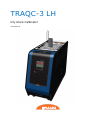
TRAQC-3 LH Dry block Calibrator User Manual User Manual TRAQC-3 LH Content 1. 1.1 1.2 1.3 1.4 1.5 1.6 1.7 1.8 2. 2.1 2.2 2.3 2.4 3. 3.1 3.2 3.3 4. 4.1 4.2 4.3 5. 5.1 5.2 5.3 5.4 5.5 5.6 6. 6.1 6.2 6.3 General .............................................................................................. 3 Warranty ........................................................................................ 3 TRAQC-3 LH Description ................................................................... 4 Standard Equipment ........................................................................ 4 CE EMC Directive 89/336/EEC ........................................................... 4 CE Electrical Safety Directive 73/23/CE .............................................. 5 Symbols Used ................................................................................. 5 Scope of this manual ........................................................................ 5 Instrument Label ............................................................................. 5 Important Knowledge ........................................................................... 6 Accuracy of the display compared to a standard .................................. 6 Stability .......................................................................................... 6 The axial homogeneity ..................................................................... 6 The boring to boring homogeneity ..................................................... 6 Functions and connections .................................................................... 7 Front .............................................................................................. 7 Top ................................................................................................ 8 Back .............................................................................................. 9 Operating instructions .........................................................................10 TRAQC-3 LH ...................................................................................10 Temperature switch ........................................................................12 End of use .....................................................................................12 Maintenance.......................................................................................13 Cleaning TRAQC-3 LH heat block and inserts: .....................................13 Cleaning the fan grille: ....................................................................13 External cleaning: ...........................................................................13 Fuse: ............................................................................................14 Storage and/or shipping ..................................................................14 Recalibration ..................................................................................14 Product Specifications .........................................................................15 General .........................................................................................15 Generation and control ....................................................................15 Option and Accessories ....................................................................15 TRAQC-3 LH 07/2014 EN Rev.1 page : 2 User Manual TRAQC-3 LH 1. General 1.1 Warranty During the design and manufacturing of this instrument the at most attention has been given to quality and durability. This manual contains information needed for the safe and effective use of the capabilities of the instrument. Please read the manual carefully before operating the instrument. By doing so possible damage to the instrument or damage caused by the incorrect use of the instrument can be avoided. TRADINCO INSTRUMENTS warrantees the instrument in accordance with the Standard Terms and Conditions of the Instrument Trade as issued by the Association bearing the name "Federation Het Instrument" (The Instrument Federation, (filed with the Clerk of Utrecht District Court on 13 January 1993 under number 16/93 and with the Chamber of Commerce and Industry in Amersfoort on 18 January 1993. A copy is available on request. TRADINCO INSTRUMENTS warrantees that this product will be free from defects in materials and workmanship for a period of 5 years from the date of shipment. If any such product proves defective during this warranty period, TRADINCO INSTRUMENTS, at its option, will either repair the defective product without charge for parts or labour, or will provide a replacement in exchange for the defective product. In order to obtain service under this warranty, Customer must notify TRADINCO INSTRUMENTS of the defect before the expiration of the warranty period and make suitable arrangements for the performance of the service. Customer shall be responsible for packaging and shipping of the defective product to the service centre designated by TRADINCO INSTRUMENTS, with shipping charges prepaid. If no defect can be found Customer may be charged for costs of the investigation. This warranty does not apply to any defect, failure or damage caused by: a. b. c. d. Improper use of the instrument. Normal wear of the product. Modification or repair carried out by or on behalf of the owner or by a third party. Implementation of modifications to the product that are not supplied or implemented by TRADINCO INSTRUMENTS. TRADINCO INSTRUMENTS and its vendors will not be liable for any indirect, special, incidental or consequential damages irrespective of whether TRADINCO INSTRUMENTS or the vendor has advance notice of the possibility of such damages. The type number of the product, as listed on the instrument tag plate, should always be mentioned in any correspondence concerning the product. TRADINCO INSTRUMENTS Industrieweg 74 Postbus 37 2650 AA Berkel en Rodenrijs The Netherlands +31 (0)10 5112911 www.tradinco.com [email protected] TRAQC-3 LH 07/2014 EN Rev.1 page : 3 User Manual TRAQC-3 LH 1.2 TRAQC-3 LH Description The use of model TRAQC-3 LH offers a number of great advantages above alternative methods of temperature calibration, but requires that any user reads the instruction manual very carefully and is aware of the fact that high temperature has to be handled with care and only in areas without hazardous fumes or fire risks and get acquainted with all the facilities offered by this temperature calibrator. Accurate temperature measurements can be assured only when it is possible physically to produce a legitimate basis for establishing traceability to temperature standards. The TRAQC-3 LH dry block calibrator is a high precision temperature calibrator ranging from 50°C to 650 °C. By setting the TRAQC-3 LH a series of different temperatures, the inserted sensor/ display/recorder can be calibrated accordingly. The maximum probe diameter is 26mm and block depth is 180mm. The TRAQC-3 LH consists of 5 main parts: The heating block is made from specially produced metal to achieve optimum heat conductivity and prevent corrosion. The heating block is heated with resistance heating elements. The instrument is electronically controlled and regulated with 2 push-buttons on the front panel and indicates the temperature in the display in the front panel. The temperature is controlled by a precision platinum resistance thermometer (RTD sensor) and an intelligent closed loop circuit. The heating block warming and cooling time is optimised with a large cooling fan and an automated shut opening and closing louver to further optimise the heating performance. RS232 communication interface. RS232 cable The aluminum housing is equipped with a carrying handle. Up to two inserts, insert puller and insulating tube can be stored inside the TRAQC-3 LH calibrator Dimensions are (LxWxH) 399.3x149.3x298mm (399.3x143.3x333mm including insulation tube) and the weight is approximately 11.5 kg. 1.3 Standard Equipment The TRAQC-3 LH will be standard equipped with the following: TRAQC-LH dry block calibrator Instruction manual (on cd) Traceable calibration report Insert Ø6,2mm bore Mains power cord RS232 cable More equipment is optional (see other accessories, chapter 6.3) 1.4 CE EMC Directive 89/336/EEC The electrical part of the TRAQC-3 LH meets the regulations according to the standards listed below: EN-IEC 61000-4-2 : 2009 EN-IEC 61000-4-3 : 2009 EN-IEC 61000-4-4 : 2009 EN-IEC 61000-4-5 : 2009 EN-IEC 61000-3-2 : 2009 EN-IEC 61000-3-3 : 2009 The unit is CE marked accordingly. TRAQC-3 LH 07/2014 EN Rev.1 page : 4 User Manual TRAQC-3 LH 1.5 CE Electrical Safety Directive 73/23/CE The electrical part of the TRAQC-3 LH meets the regulations according to the standard listed below: EN 61010-1 : 1995 The unit is CE marked accordingly. 1.6 Symbols Used Warning for conditions or practices that could result in personal injury, loss of life and/or in damage to the product or other property. Attention signal or remark Danger of electrical shock 1.7 Scope of this manual This manual contains information for instruments built after January 2014. This manual is a user manual on how to operate the instrument; it is not a calibration instruction manual. As Tradinco Instruments continuously strives to improve its products, specifications of instruments may be altered without further notice. 1.8 Instrument Label Type No. : TRAQC 3LH Serial No. : xxxx-x Range : ambiant +5 °C to 650 °C Power : 230 Vac, 50 – 60Hz, 2000 W Fuse : 2x 10A / 250 VAC Date : XXX Berkel en Rodenrijs, The Netherlands E-Mail : [email protected] Made in The Netherlands TRAQC-3 LH 07/2014 EN Rev.1 page : 5 User Manual TRAQC-3 LH 2. Important Knowledge The factors which characterize a dry-block oven are: Accuracy of the display compared to a standard The stability over time The axial homogeneity of the block The boring to boring homogeneity The European Association of National Metrology Institutes, Euromet CG-13 Guideline describes this in detail. This paragraph will briefly discuss the parameters above. Please note that the importance and pit-falls with these parameters are often overlooked. More important is to specify these parameters correctly in order to know the measurement uncertainty. 2.1 Accuracy of the display compared to a standard Usually a dry-well block oven is used in combination with a standard temperature measuring instrument. A Unit under test (UUT) is in that instance calibrated against the said standard. Important then is to have a dry well which can hold its temperature very stable. 2.2 Stability Is defined as temperature variation as function of time. The Euromet CG-13 guideline uses a 30 minute interval. This makes clear that a good stability over a long period of time is actually a good stability. 2.3 The axial homogeneity Is probably the most important (and forgotten) parameter of a dry-well block calibrator. If one uses a probe with 5 mm length and measure at intervals the temperature while pulling out this probe, one can determine the axial gradient. Due to its geometry, isolation characteristics, the heat loss of the probe etc. the heating bloc is not homogenise in temperature. Differences in the order of magnitude of degrees of Celsius are often found. This parameter is very important because usually it is not known how long a PT 100 in a probe is, or at what position in the probe (or UUT) the PT100 or Thermocouple is placed. The Euromet CG-13 Guideline mentions a 4 cm homogenise zone as a kind of a norm. 2.4 The boring to boring homogeneity Most dry-well block calibrators have an insert with more than one boring. If there is one boring this boring is usually in the centre. An ideal symmetric situation with internal heaters elements is then automatically provided. With two borings a symmetrical position of both borings can be reached if the position is of each boring is at equal distance to the heating element. A mark of the insert should then be provided. This mark should be placed in line with the mark on the block. Again this is often overlooked but an important factor in determining the uncertainty of a calibration. Once one is aware of this issue one can easily take appropriate counter measures. TRAQC-3 LH 07/2014 EN Rev.1 page : 6 User Manual TRAQC-3 LH 3. Functions and connections 3.1 Front 1 4 2 3 1) 2) 3) 4) 5) 5 Display Pushbutton used for factory settings Switching indicator Led Up and down pushbuttons Temperature switch 4mm sockets TRAQC-3 LH 07/2014 EN Rev.1 page : 7 User Manual TRAQC-3 LH 3.2 Top 2 3 3 4 1 5 6 7 1) 2) 3) 4) 5) 6) 7) Insert grabber Insulation tube storage hole Insert storage holes Carrying handle Opening and closing louver Heat block well Upper grill TRAQC-3 LH 07/2014 EN Rev.1 page : 8 User Manual TRAQC-3 LH 3.3 Back 5 1 2 3 4 1) 2) 3) 4) 5) 9 Pin RS232 port ON/OFF Switch Fuse drawer Mains power cord connector Carrying handle TRAQC-3 LH 07/2014 EN Rev.1 page : 9 User Manual TRAQC-3 LH 4. Operating instructions 4.1 TRAQC-3 LH Note: Please observe proper grounding of the instrument. Use the supplied power cord if possible. Be careful, the top parts around the heat block of the TRAQC-3 LH, especially the “upper grill” becomes very hot. Also the air above the instrument heats up. When operating, be careful not to burn yourself and that the heated air can freely flow into the room without damaging/interfering anything. Place instrument in a way that the ventilation openings on the underside and side panels of the instrument are not obstructed for proper measurement results. Connect the power cord to the unit and turn it on. When the TRAQC-3 LH starts up, a sequence of different numbers will be shown in the “display”. - 8888: check all segments of the “display”. Prog, then a number: this shows the software revision number, XXXX : a code number for manufacturers use only, XX: a code number for manufacturers use only, Hr XX: The amount of hours the TRAQC-3 LH has been powered, the six digits after the “Hr” represent the hours up to 99999.9 hrs XXXX: see above. Place the correct insert for the unit under test into the “heat block well”. To ensure a good calibration, the probe diameter has to be 0.2mm smaller than the diameter of the bore in the insert. TRAQC-3 LH 07/2014 EN Rev.1 page : 10 User Manual TRAQC-3 LH Never handle very hot inserts. The insert should cool down to less than 200°C before being placed in one of the “insert storage holes”. Always use the insert grabber. Place the insulation tube onto the insert. Never handle the insulation tube when it’s hot. The insulation tube should cool down to less than 200°C before being placed in “insulation storage hole”. Always use the insert grabber. Always place the insulation tube. The passing air can seriously affect the calibration due to the passing air of the cooling fan onto the, to be calibrated probe. Place unit under test (RTD, thermo couple, temp. switch, etc) in the insert bore. It is recommended to use the centre hole for all measurements. At special request from customers, the pattern of insert holes may differ, a temperature reference hole may be ordered as a extra option. See also section 2.4 for proper use of the borings in the insert. With the “up and down pushbuttons” the desired temperature can be set between 50°C and 650°C. Make sure the “upper grill” is not blocked. Set the first calibration/test point. After 1 second the “display” indicates the actual temperature. After the unit has reached its set-point the specified accuracy is reached after 5 till 10 minutes. Observe at least 35 minutes stabilisation time when the set temperature is reached, in order to achieve the specified stabilization accuracy. TRAQC-3 LH 07/2014 EN Rev.1 page : 11 User Manual TRAQC-3 LH While heating a led (O1 or A1) in the left upper corner of the “display” will flash. Flashing will be intermittent and regular as the unit reaches the set temperature. Follow steps 5 thru 8 for every calibration point. For decreasing the temperature the same procedure as described above must be followed. To provide provide an optimum use of the TRAQC-3 LH, all control functions are available through a RS232 interface. With the Tradinco AutoCal Software, the TRAQC-3 series dry block calibrators communicate with a PC. This MS Windows based software is completely 'MENU' controlled and allows the user to program pre-fixed calibration routines and run calibration routines fully automatically. The environment (temperature and draught), length and the mass of the probe may influence the measurement considerably. If the manufacturer has enabled “pushbutton used for factory settings”, one has access to a part of a menu structure. Use of this feature is not required; any change may seriously change the behaviour of the instrument. 4.2 Temperature switch Connect the temp-switch to the “temperature switch 4mm sockets” and insert the switch in the boring of the insert. With the “up and down pushbuttons” the desired temperature can be set between ambient +5°C and 650°C. Make sure the “upper grill” is not blocked. Observe at least 35 minutes stabilisation time when the set temperature is reached, in order to achieve the specified stabilization accuracy. Adjust or check the temp-switch so that the “switching indicator led” switches at the desired temperature. 4.3 End of use Do not switch the instrument off or disconnect the mains lead until the instrument has reached a temperature below 70°C. In order to cool down the TRAQC-3 LH quickly, set the set temperature to 50°C,. When a temperature below 70°C is reached, turn off the TRAQC-3 LH TRAQC-3 LH 07/2014 EN Rev.1 page : 12 User Manual TRAQC-3 LH 5. Maintenance Before any maintenance is undertaken the TRAQC-3 LH must be cooled to room temperature. The sequence to cool down the TRAQC-3 LH is described in chapter 4.3. When the TRAQC-3 LH is unplugged wait until it is cooled down to room temperature and unplug the mains power cord. 5.1 Cleaning TRAQC-3 LH heat block and inserts: A small amount of dust or pollution can cause jams when between the inserts and the “heat block well”. To prevent this: Remove the insert from the “heat block well” at regular intervals Clean “heat block well” with a dry cloth. If the “heat block well” is very polluted it can be cleaned with a brass tube wire brush. After cleaning flush the “heat block well” with compressed air. Clean the bore and outside of the insert with a dry cloth. If the bore of the heat insert is very polluted it can be cleaned with a brass tube wire brush. The outside with a brass wire brush. After cleaning flush the bore of the insert with compressed air and clean the outside with a dry cloth. If the TRAQC-3 LH is not operated for longer periods or moved, remove the insert from the heat block and store the insert in one of the two “insert storing holes”. 5.2 Cleaning the fan grille: On the bottom, the TRAQC-3 LH is fitted with an air grille via which cooling air enters the TRAQC-3 LH. Clean the grille at regular intervals (vacuuming or brushing) depending on the level of air pollution. 5.3 External cleaning: Clean the outside of the TRAQC-3 LH with a damp cloth and some water or with a solvent free and mild cleaning agent. TRAQC-3 LH 07/2014 EN Rev.1 page : 13 User Manual TRAQC-3 LH 5.4 Fuse: With a flat screwdriver (max. 2.5mm) press down both snap fittings of the “fuse drawer”. Take out the “fuse drawer” and replace both fuses. Two Fuses: 2x 10A antisurge, 250VAC must be used. 5.5 Storage and/or shipping Before storage and/or shipping the TRAQC-3 LH must be cooled to a temperature below 50°C. The sequence to cool down the TRAQC-3 LH is described in chapter 4.3. After the TRAQC-3 LH is cooled down, turn the TRAQC-3 LH off and unplug the mains power cord. When the TRAQC-3 LH is shipped / stored: Place the insulation tube in the “Insulation tube storage hole”. Remove the insert from the heat block and store the insert in one of the two “insert storing holes” or in the insert storing hole in the shipping case. Store it indoors, in a temperature between 0 and 50° Celsius. Place the case a horizontal position. 5.6 Recalibration The TRAQC-3 LH is adjusted and tested with measuring equipment in accordance with recognized national standards prior to delivery. The TRAQC-3 should, depending on the application situation, be inspected at appropriate intervals. We recommend you to return the calibrator to Tradinco Instruments at intervals of max. 12 months for recalibration and service. TRAQC-3 LH 07/2014 EN Rev.1 page : 14 User Manual TRAQC-3 LH 6. Product Specifications 6.1 General Display Resolution Switch test Interface Supply voltage Power consumption Fault protection Fuse Thermal Protection switch Safety Conformity EMC Well depth Well diameter Weight Dimensions (LxWxH) : Dual digit led displays (Upper 10mm, Lower 8mm) : 4 digits, 0.1 °C/°F : Powerless switch, LED indicator, 5 VDC, 16mA max. : RS232 for use with AutoCal Software : 230VAC, 50/60 Hz : 1800 Watt : Internal sensor break detection : 2x 10A antisurge, 250 VAC : 140°C : NEN-EN-IEC 61010-1. : NEN-EN-IEC 61000-4-3, -3-2, -3-3, -4-2, -4-4, -4-5 : Max. 175mm, recommended 95mm : Max. Ø26mm : 11.5 KG, without power cord, incl. insert : 399.3x149.3x298mm (399.3x143.3x346mm including insulation tube) 6.2 Generation and control Temperature range Accuracy Stability Worst case boring to boring difference Stabilization Axial temperature Homogeneity, 40 mm at 95 mm well depth Heating time ambient to 650°C Cooling time 650°C to 100 °C All specifications : 50°C to 650°C : ±0.5°C up to 500°C ±1°C up to 650°C : ±0.04°C. : 0.3°C (3 borings in insert) : 35 minutes : 0.45°C at 500°C and 0.8°C at 650°C and in accordance with Euramet CG-13 : 30 minutes : 65 minutes : ambient temperature 20°C ±2°C 6.3 Option and Accessories RvA accredited calibration certificate for temperature, traceable to international standards AutoCal® calibration management software Cleaning set (brass wire brush and brass tube wire brush) Insert; 1, 2, 3 or 4 bore(s) or undrilled. Sizes upon request. Carrying case Carrying case Rugged A rugged carrying case which offers maximum protection during transport. This case is watertight and is secured by two safety latches. It stores the TRAQC-3 LH, up to 3 inserts, insert grabber, mains power cord, cleaning set, manual and calibration certificate. TRAQC-3 LH 07/2014 EN Rev.1 page : 15 User Manual TRAQC-3 LH TRADINCO INSTRUMENTS Industrieweg 74 Postbus 37 2650 AA Berkel en Rodenrijs The Netherlands +31 (0)10 5112911 www.tradinco.com [email protected] TRAQC-3 LH 07/2014 EN Rev.1 page : 16 User Manual TRAQC-3 LH TRAQC-3 LH 07/2014 EN Rev.1 page : 17