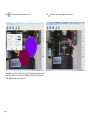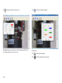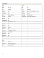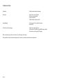
1
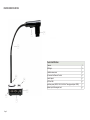
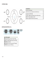
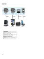
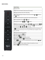
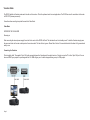
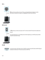
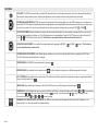
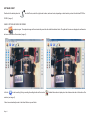
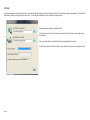
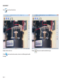
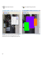
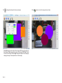
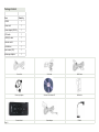
DC400i Visualiser
Document Camera
Please read this manual carefully before operating the document camera and keep it for reference
Page 1
USER MANUAL
Safety Measures
Notice: PLEASE READ CAREFULLY BEFORE USE
Use the document camera (Visualiser) under the rated electric conditions.
Do not place the document camera (Visualiser) on an unstable surface. It may fall causing injury or damage.
Do not place this device directly under sunlight or near heaters.
Do not place this device near water.
Keep the camera away from acid or alkali gas.
Do not place this document camera (Visualiser) in humid, dusty, windy or vibrant locations.
The recommended operating environment is:
Temperature:
0ºC—45ºC (32ºF-113ºF)
Humidity:
less than 75%
Always unplug BEFORE cleaning the device. Use a damp soft-cloth for cleaning. Do not use volatile solvent.
When this equipment functions abnormally, such as smoke, smell, noise, immediately unplug and call for professional assistance.
Unplug the document camera (Visualiser) when not in use.
Page 2
Page
INTRODUCTION / WARRANTY 4
PARTS IDENTIFICATION
5
CONTROL PANEL
6
INPUTS AND OUTPUTS
6
CONNECTIONS
7
REMOTE CONTROL
8
VISUALISER OR VIDEO MODE
9
OPERATING THE VISUALISER
9/10
FEATURES
12
LIGHT
ZOOM IN AND ZOOM OUT
FOCUS ADJUSTMENT
BRIGHTNESS ADJUSTMENT
WHITE BALANCE ADJUSTMENT
FREEZE IMAGE
MIRROR IMAGE
SPLIT SCREEN
IMAGE SAVE
IMAGE RECALL
USB IMAGE CAPTURE AND VIDEO RECORDING
COMPUTER REQUIREMENTS
13
SOFTWARE
14/20
SPECIFICATION
21
TROUBLE-SHOOTING
22
PACKING LIST
23
Page 3
INTRODUCTION
Thank you for purchasing this product, with sensible use it will give years of good service.
Like many of us, referring to the user manual is often a last resort so we recommend you make an electronic copy and a hard copy for future
reference.
We have designed the product so that it’s easy to understand and operate. Most of the core functions can be operated from the Visualiser front
panel, leaving some of the special functions such as freeze, mirror, image store and rotate on the remote. It’s therefore important that you take
care of the remote
We hope you enjoy using the product.
5 Year Warranty
Warranties give you peace of mind, even so, you need to take care of your DC400i and understand what’s covered and what’s not.
What’s covered?
In general the unit is covered by a 5 year warranty which takes into consideration failures which are outside of your control.
What’s not covered?
•
•
•
Physical damage / abuse
Fluid ingress
Broken cables due to twisting / excessive force
For full warranty details please visit www.optomaeurope.com
Compliant
The DC400i is RoHS compliant, which means it meets the rigorous European Union’s requirements for restriction of the use of certain hazardous
substances in electrical and electronic equipment.
Page 4
PARTS IDENTIFICATION
1
2
3
Parts Identification
4
5
6
8
7
Page 5
Camera
1
LED light
2
Flexible camera arm
3
IR receiver for Remote Control
4
Control panel
5
SD Card Slot
6
Interface panel (HDMI, VGA Out & Past Through ports plus USB2)
7
Mains Input & Kensington lock
8
CONTROL PANEL
Control Panel
5
3
6
4
4
1
2
5
INPUTS AND OUTPUTS (I/O’s)
Input / Output panel
VGA IN [VGA (RGB) signal input (15 pin D-SUB)]
VGA OUT [VGA (RGB) signal output (15 pin D-SUB)]
HDMI [HDMI signal output]
USB2 [USB2 slave, used to connect with PC/Laptop]
SD CARD [SD card slot. (32 GB Max)]
Page 6
6
Power [Turn on/off power]
1
Auto [Auto focus, color adjustment and white balance]
2
Lamp [Turn on/off LED light]
3
FOCUS+/- [Adjust focus manually, focus far and focus near]
4
BRIGHT+/- [Image brightness control]
5
ZOOM+/- [Image zoom-in and zoom-out control]
6
CONNECTIONS
VGA CABLE
PC or Laptop
VGA CABLE
Panel or Projector
CONNECTIONS
VGA IN [VGA-in from PC/Laptop]
VGA OUT [VGA-Out to Panel or Projector]
HDMI [HDMI-Out to Projector or Panel]
USB2 [USB2 slave, used to connect with PC/Laptop]
Page 7
HDMI CABLE
Projector or Panel
USB CABLE
Laptop or PC
REMOTE CONTROL
Remote Functions
Power [Power ON/OFF]
FPS [Switch the frame rate between 20 (Visualizer mode) and 30 (video mode)]
RES [Toggles output resolutions: SXGA, UXGA, 720P and 1080p]
USB [Switch USB functions between “Disk mode” and “Video mode”, use the buttons
press to confirm]
and
to select, then
DEL [Press to delete the selected pictures, keep pressed for 2 seconds to delete all saved pictures]
Bright +/- [Image brightness control use
and
to adjust]
Focus+/- [Adjust focus manually with and then press to confirm]
RECALL [Press to view your saved images, use the buttons
and
to change pages and use buttons and
to select your picture choice then press to confirm. In recall mode press or to zoom the image in or out.
You can also use buttons
and
plus and to move the image]
The
button allows you to take a snap shoot of your image and save this to either SD Card or Internal memory. (200
images can be saved to internal memory) but a lot more if using a SD CARD, the amount is dependent on the cards
size i.e. up to (32 GB).
AUTO Adjusts white balance and focus automatically.
Zoom +/- Zoom in/out control using
or
buttons.
MIR Use this button to flip the camera image.
Split Use the Split button
to have two images on your screen.
Freeze Use the Freeze/Unfreeze button
to freeze/unfreeze an image.
TITLE Title
freeze mode. In this mode you can adjust the position of the frozen title with buttons
also adjust the size with or
PIP Picture in picture
Rotation Rotate
Page 8
click to select a saved picture to display on the lower right corner of a screen.
the image in 90°/180° and 270° degrees.
or
and
Visualiser Mode
The DC400i defaults to Visualiser mode each time the unit is turned on. This is the preferred mode for most applications. The DC400i can view & record video in this mode
at 20/30 FPS (frames per second)..
If smoother video recording is required then switch to Video Mode.
Video Mode
OPERATING THE VISUALISER
Powering on
After connecting the external power supply the red led in the center of the DC400i will flash. This indicates the unit is in standby mode. To start the Visualiser simply press
the power-on button via the main control panel or the remote control. The led will turn to green. Please Note: It takes 3~4 seconds before the Visualiser is fully powered and
ready to use.
Connecting the Visualiser
This is simplicity itself. The supplied 15 pin VGA cable connects between the Visualiser and the output devise i.e. Projector or monitor/TV via the 15pin VGA port. You can
also use HDMI if your projector or panel supports this I/O. HDMI will give you a far better image and also goes up to 1080p output.
VGA CABLE
Page 9
HDMI CABLE
VGA In
VGA CABLE
VGA In is used to show your desktop on the camera. When you run the supplied software and show/project onto a white
board it allows you to annotate over your image so you can highlight points of interest or draw over the image.
USB Connection
The USB port allows you to view the camera output via the PC. You will need to install the PC software which is described later in
this manual.
USB CABLE
Once connected this will allow you to record endless pictures and video files (depending on your Hard Disk capacity) the software
also provides simple annotation of images.
SD CARD
You can also save images to an SD Card to review on a PC/LAPTOP or any device that reads SD Cards like the ML500 LED projector
from Optoma, the max card size is 32 GB. (You cannot record video to the SD Card)
Page 10
Positioning the Camera – Rotation & Mirror
Normally the camera is positioned over documents and objects alongside the Visualiser. Using the remote control you can rotate
the image through 90, 180 or
270 degree increments so that the captured image appears straight to the viewer. You can also use the mirror
function in a similar way. Using the combination of
rotation and mirror functions means you have flexibility when positioning the camera.
Page 11
FEATURES
LED LIGHT The DC400i uses eco-friendly, low power LED lamps which are cool to the touch and mercury free. Due to the excellent sensitivity of
the camera the lamp is seldom required. Adjusting the light balance from the remote control can often provide clear vivid images.
ZOOMING IN AND ZOOMING OUT With 14x optical zoom combined with 16x seamless digital zoom the DC400i enables you to view items in immense detail. DC400i’s advanced optical system features high speed auto focus capability that ensures instant auto focus when you quickly zoom
in and out of any object. You can also manually adjust focus to satisfy any special viewing needs by pressing ZOOM+ or ZOOMFOCUS ADJUSTMENT When the Visualiser is turned on the focus automatically adjusts, it is not necessary to re-adjust the focus if you are only
working with flat materials (text, photos, etc.). Only 3D objects require a focus adjustment. Press the “AUTO” button to auto focus. Press the FOCUS+
or FOCUS- buttons to focus manually. This function is accessible from the remote control and the base unit.
BRIGHTNESS ADJUSTMENT You can adjust the camera brightness by pressing the BRIGHT +
only accessible from the remote control.
or BRIGHT -
buttons. This function is
WHITE BALANCE ADJUSTMENT Under different lighting conditions you may need to adjust the white balance by pressing the AUTO button.
The AUTO button also assists with fine focus changes.
FREEZE IMAGE Use FREEZE to freeze and unfreeze the image.
MIRROR IMAGE (Only available from the remote control)
The mirror image function gives you a different perspective of an object.
SPLIT SCREEN (Only available from the remote control) The split screen offers the capability of comparing two images or comparing two different
views of one object side by side.
IMAGE SAVE (Only available from the remote control) The DC400i can store up to 200 images in its internal memory.
IMAGE RECALL (Only available from the remote control) Click the recall button to view saved images, use the buttons
and
to change pages
and use buttons and to select your picture choice then press to confirm. In recall mode press or to zoom the image in or out.
You can also use buttons
and
plus and to move the image.
USB IMAGE CAPTURE AND VIDEO RECORDING The USB2 port can be used to store images and video clips from the Visualiser on your
computer. (Note: You will need to install the supplied software).
Page 12
COMPUTER REQUIREMENTS
The PC’s hardware and software configurations shall not be less than the following requirements:
•
•
•
•
Operating system: Windows XP/Win7/Win8
CPU: Pentium 4 1.8Ghz or better
Physical memory: 512M or more
Video memory: 64M or better
Windows XP and Vista do not support USB 2 without a driver so you must install the supplied USB2 driver to get your DC400i working.
NOTE:
You can also use the camera as a webcam with software like SKYPE or some other camera software the DC400i will work with the OS built-in USB2 drivers. Just select USB
or UVC Camera device.
SKYPE also works with Windows XP but you must install the USB Driver located on the DC400i’s CD first
SKYPE is fully supported under- Skype – Tools – Options – Video Settings
Use the supplied USB2 cable and connect from the DC400i to a spare USB port on your PC/Laptop.
Please turn on the DC400i first so the green power-on button is on, this may take 30 or so seconds, then plug-in the USB cable so your PC/Laptop can detect a new device
then run the Optoma USB software.
Page 13
SOFTWARE START
Double click the desktop short-cut
then click Device; select the right model number, as shown below, depending on which model you have this will show DC300i or
DC400i. (Image 1)
IMAGE CAPTURE AND VIDEO RECORDING
Left click to capture images. The captured images will be automatically saved into the default destination folder. The path and file name are displayed in software sta
tus bar on the bottom of the window. (Image 2)
(Image 1)
Left click
(Image 2)
to start recording. During recording the settings button will be inactive.
window. (see image 2)
Video’s are automatically saved in the default folder or pre-set folder.
Page 14
Detailed information is displayed on the software status bar at the bottom of the
SETTINGS
The captured images and recorded videos will be saved into the folders of Images and Videos respectively, which are created by the system automatically. To set a different
path where you wish your image’s or video saved, click on the left side of the window, a pop up dialog box appears below.
Save the captured images into a different folder
Click the button next to the “select a folder to save picture files” text box to set the path for captured images.
Save a recorded video into a different folder and set up parameters for videos
Click the button next to the “Select a folder to save video files:” text box to set the path for videos.
Page 15
IMAGE MODIFY
Click
you will see this interface:
Graphic selection and move
Clicking
the image.
Page 16
allows to select and move lines, circles etc to a different position within
Clicking
allows you to create lines within the image.
Click
to change the setting of the chosen line
Line width change the width of the line. X/Y change the position of the line.
Color change the color of the line. Width, Height Change the angle of the line.
Page 17
Click
to place a rectangle in the image, shown as below
Click
to change the setting of the chosen rectangle
Line width change the line width of the rectangle. X/Y change the position of
the rectangle. Color change the line color of the rectangle. Fill Color Tick it to
fill color in the rectangle. Width, Height Change the shape of the rectangle by
changing the angle of two adjacent lines of the rectangle.
Page 18
Click
to place a circle in the image, shown as below
Click
to change the settings of the chosen circle
Line width change the line width of the circle. X/Y change the position of the circle.
Color change the line color of the circle. Fill Color Tick it to fill color in the circle.
Width, Height change the size of the circle.
Page 19
Click
to place a curve in the image, shown as below
Click
to change the setting of the chosen curve
Line width change the line width of the curve. X/Y change the position of the
curve. Color change the line color of the curve.
Page 20
Click
to change the setting of the graphic
Graphic delete
Click
to delete the chosen graphic.
Click
to delete all graphics placed in the image.
SPECIFICATIONS
IMAGE
OTHER
Sensor
1.2.5” CMOS
Input
VGA
Pixels
5 Megapixel
Output
HDMI and VGA
Frame Rate
20/30
Dimensions
Setup: 6.7”×19.1”×13.5” / Folded: 6.7”×7.2”×13.5”
Color adjustment
Yes
Weight (net)
4.4lbs/2kg
Rotation
90, 180 and 270 degrees
Power Supply
12V DC Power Adaptor
White balance
Auto/manual
Software Support
Microsoft Windows, Apple MAC OSX
Mirror Image
Yes
Brightness adjustment
Yes
Output resolution
SXGA, 720p, UXGA and 1080p
Image split
Yes
Image Freeze
Yes
Video recording
Yes (via USB)
Text mode
Yes
Image capture
Yes (200 images Internal Memory)
SD CARD Support
Yes (Max 32 GB)
Remote Control
Yes
Kensington Lock
Yes
OSD
Yes
OPTICS
Focus
Auto/manual
Shooting area
Max: 14.7”x11.1”, Min: 0.1”x0.1”
Zoom
14 x optical, 16 x digital
Page 21
TROUBLE-SHOOTING
Symptoms
Possible causes/counter-measures
No Image
Power Cord is not connected
Cables are not connected
Power is turned off
Output resolution not set correct
Image Bending
Camera is out-of-line, adjust the camera
Press AUTO
Out of focus or blurring image
Object is too close to the lens
Focus point is full ZOOM, press ZOOM minus to adjust
Auto-focus is not on: press AUTO again
Dust or condensation could be on the lens, use a soft damp cloth to clean
If the problem still remains after checking the above, consult your dealer or authorized service personal
Page 22
Package Content
Item
Quantity
DC400i
1
Power cord
1
Power adaptor(12V/2A)
1
VGA cable
1
USB (2.0) cable
1
Remote control
1
AA batteries
1
User manual (CD)
1
Microscope Adapter
1
Page 23
Power Cord
VGA Cable
USB2 Cable
Microscope Adapter
Software/ User Manual CD
AA Batteries
Remote Control
Power Adapter
DC400i