1
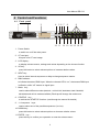
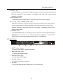
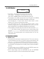
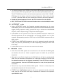
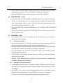
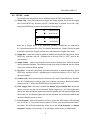
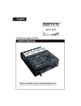
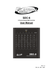
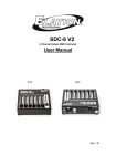
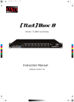
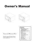
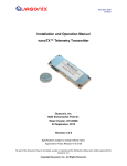
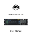
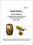
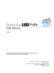
DR-512
USER INSTRUCTIONS
( 24-004-1126
Rev 1.1 )
DMX
POWER
CF CARD
DR-512
UP
NEXT
MODE
START-UP
SEQ 1
SEQ 2
SEQ 3
SEQ 4
DOWN
ENTER
CARD
SHUT-DOWN
PLAY
PAUSE
STOP
RECORD
E-mail: [email protected]
Internet: www.botex.com
User Manual DR-512
Table of contents
1 General Instruction..........................................................................................3
2 Features............................................................................................................3
3 Notice Information .......................................................................................... 3
3.1 Warnings.....................................................................................................3
3.2 Copyright.....................................................................................................3
4 Control and Functions.................................................................................... 4
4.1 Front panel..................................................................................................4
4.2 Rear panel...................................................................................................5
5 LCD display ..................................................................................................... 6
6 Operation Modes .............................................................................................6
6.1 Manual mode ..............................................................................................6
6.2 AUTOSTART mode ....................................................................................7
6.3 DMX MON mode.........................................................................................7
6.4 DMX TRIGGER mode ................................................................................8
6.5 PROGRAM mode........................................................................................8
6.5.1 Recording operation...........................................................................8
6.5.2 Changing the sequence name ...........................................................8
6.6 SETUP mode ..............................................................................................9
7 External Terminals ........................................................................................ 10
8 Note Information for usage .......................................................................... 10
9 Troubleshooting (FAQ) ................................................................................. 11
10 Specifications...............................................................................................11
2
User Manual DR-512
1 General Instruction
DR-512 is a professional DMX recorder with many useful functions. This unit can
translate standard DMX512 signals into recorded data, and send them out at any convenient
moment. These signals can be recorded to both the internal storage and the external CF card.
For internal storage, there are six sequences to be used availably : sequences I01~I04,
STARTUP and SHUTDOWN. And for CF card, there are 33 different sequences (E01-E33)
available. This product offers SMPTE trigger function. There are 6 different modes usable :
MANUAL, AUTOSTART, DMX MON, DMX TRIGGER, PROGRAM and SETUP .
2 Features
•
Professional DMX recorder, access to memory and CF card.
•
4 sequences (I01-I04) + Startup + Shutdown, available in memory.
•
33 sequences (E01-E33) available in CF card.
•
Capable of PLAY, PAUSE and STOP functions.
•
Manual / Autostart / DMX monitor / DMX trigger / Program / Setup mode.
•
24 / 25 / 30 frames SMPTE signal available.
•
Exclusive 32 MB CF card is recommended and can be provided at user’s request.
•
DMX 3Pin input/output, SMPTE 3Pin input/output, 9Pin connector.
•
Line remote control recalls PLAY, STOP and RECORD functions.
•
2×16 characters LCD screen.
3 Notice Information
3.1 Warnings
•
keep the unit dry, do not expose it to water or high levels of humid.
•
Do not try to dismantle or modify the product.
•
Turn off the power if not using this unit for a long time.
•
Any strong shocks or vibration may result in malfunction.
•
This unit must operated by adults, do not allow children to play with it.
3.2 Copyright :
No part of this product can be reproduced, transmitted, or translated into any language
in any form without authorized permission.
3
User Manual DR-512
4 Control and Functions
4.1
Front panel
2
1
3
4
5 6 7
8
9
DMX
POWER
DR-512
CF CARD
UP
NEXT
M ODE
START-UP
SEQ 1
SEQ 2
SEQ 3
SEQ 4
DOWN
ENTER
CARD
SHUT-DOWN
PLAY
PAUSE
STOP
RECORD
10 11
12 13 14 15 16 17
1. Power Switch:
to switch on or off the main power.
2. CF card port :
this port is for CF card usage.
3. LCD-display :
to display relevant menus, settings and values depending on the chosen function.
4. UP key :
press this button to select relevant options or increase relative values.
5. NEXT key :
Used to select internal sequences or help to change sequence names.
6. DMX indicator :
to indicate the state of DMX input. When the relevant LED is “on”, that means DMX input
is effective, while “off” means no signal input.
7. Mode
key :
used to select different modes (MANUAL, AUTOSTART, DMX MON, DMX TRIGGER,
PROGRAM and SETUP modes available). Each tap will change the mode once.
8. STARTUP key :
to activate the STARTUP function. (read through the manual for details)
9. 1~4 sequence
keys :
used to select one of the possible sequences (I01~I04).
10. DOWN key :
press this button to select relevant options or decrease relative values.
11. ENTER
key :
press this key to confirm your operation or enter the relevant menu.
4
User Manual DR-512
12. CARD
key :
to switch between the operations for internal storage and the CF card storage. Relevant
LED “on” means CF card operation is available, while LED “off” means internal
operation is available.
13. SHUTDOWN
key :
to activate the SHUTDOWN function. (read through the manual for details)
14. / 15. / 16.
PLAY / PAUSE / STOP
keys :
these three keys are used for the flow control. By pushing one of these keys a
chosen sequence can be started, stopped, or finished. How the keys react in the
different modes and what other functions are executed is explained in detail in the
chapter of the modes.
17. RECORD
key :
in the PROGRAM mode, the recording of a new sequence can be prepared with the
RECORD key. In order to do so, user should choose a sequence, then push the
RECORD key and start the recording with the PLAY or PAUSE key.
4.2 Rear Panel
PUSH
PUSH
PUSH
1
SMPTE OUT
SMPTE IN
1
DMX OUT
2
2
3
4
5
6
7
8
9
1
2
3
4
5
6
7
8
9
PLAY
SEQ A
SEQ B
STOP
RECORD
PRG-MODE-LED
RECORD-LED
PLAY-LED
GND
Seq A Seq B
Num
0
0
I01
0
1
I02
1
0
E01
1
1
E02
DC INPUT:
9-12VDC, 500mA Min
DMX IN
Made in PRC
4
3
1. SMPTE output / input :
To output / input SMPTE signals via this port.
2. DMX output (5pin / 3pin) :
To output relative DMX signals.
3. DMX input (5pin / 3pin) :
To input relative DMX signals.
4. Terminal connector :
To connect with external terminals.
5. DC input :
To plug in an external power supply (DC 9-12V, 500 mA Min).
5
5
User Manual DR-512
5 LCD Display
I01
MANUAL
Sh01
■
00:00:00
• Press “PLAY” , “►” will appear on the top right corner of the LCD;
Press “PAUSE”,
“ll” will appear on the top right corner of the LCD;
Press “STOP”, and “■” will appear on the top right corner of the LCD.
• The characters in the middle of the first line on the LCD stand for the MANUAL,
AUTOSTART, DMX MON, DMX TRIGGER, PRG MODE or SETUP mode.
• In the first display line , “I” means “internal”, while “E” means “external” , and the
following “01~33” means one of the sequence numbers.
• In the second display line, “Sh01” means one of the Sequence names. It can be
amended by using the “Enter” key under PROGRAM mode only. But on the other
hand, the StUp(START UP) and StDN(SHUTDOWN) can not be amended.
• The time displays on the bottom right corner of the LCD. When it shows like “××:×
×:××” (Hour, Minute, Second), that means the time of internal storage. While
shows like “××:××:××:××” (Hour, Minute, Second, Frame), that just means the
SMPTE time. The time-display pattern can be switched through “Sys Time” item
under SETUP mode.
6 Operation modes
6.1 MANUAL mode
• This mode has the most freedom to operate upon this unit. The user can select any
one of the sequences at any time to run, pause or stop the current sequence. And
further more, the operating upon STARTUP and SHUTDOWN are also available.
• For internal storage, select one of the I01-I04 sequences and press the PLAY key to
run the sequence. This sequence will run circularly unless you press the PAUSE or
STOP key.
• For internal storage, press the STARTUP key, then the STARTUP sequence will
circulate once, and other sequences will run subsequently.
• Still for internal storage, press the SHUTDOWN key, then the SHUTDOWN
sequence will circulate for one time, and other sequences will be stopped.
6
User Manual DR-512
• For external storage, press CARD key, the relevant LED will light up, that means you
have entered the CF card operation(CF card should be firstly formatted before use).
The UP / DOWN keys can be used to choose sequences, and the PLAY / PAUSE /
STOP keys can be used to control the running of sequences. When under the state
of “STOP”, press the CARD key for a second time to return to the internal operation.
• Should the selected sequence not exist, the PLAY function will not be effective.
• NEXT, ENTER and RECORD functions will disabled when under the MANUAL mode.
6.2
AUTOSTART
mode
• Under AUTOSTART mode, the foregoing recorded sequences can be rerun
automatically (To CF card , the sequences of STARTUP and SHUTDOWN will not be
trigged). During sequence running, press STOP key to activate the SHUTDOWN
sequence, when it stops running, all sequences will be stopped.
• AUTOSTART can be executed once. After the STARTUP sequence finished, the
selected sequences will run automatically, and relevant operation can be done
manually. Subsequently press the STOP key, the SHUTDOWN sequence will run
within a cycle.
• STARTUP and SHUTDOWN sequences can not be operated manually under this
mode, they can only automatically run after respectively pressing the PLAY and
STOP keys.
• AUTOSTART can be rerun the next time when the unit restarts.
6.3
DMX MON
mode
• Under this mode, DMX signals can be monitored. In the case that the DMX signals
are disabled, this unit can initiate a prepared system to enable the pre-selected
sequences.
• When there is an effective signal input, the DMX indicator will light up, and the signal
(DMX Thru) will be send out through this unit. If the signal is missing, STARTUP and
the selected sequences will be triggered automatically. Press STOP key to stop the
running sequences. After the SHUTDOWN sequence run over, all the operation will
be finished.
• This unit can only check the effective DMX signals. If there is no data input, the
pre-selected sequences will be output normally.
• STARTUP and SHUTDOWN sequences can not be operated manually under this
mode. And the AUTOSTART mode may be available for reference to the operation
upon MANUAL mode.
7
User Manual DR-512
• Once received effective DMX signals, the running sequences will be stopped
automatically. Function upon PLAY, PAUSE and STOP keys will disabled.
• Should the DMX signals be disabled, operation could be done manually.
6.4
DMX TRIGGER
mode
• Under this mode, the first four DMX channels(Ch1~Ch4) can be used to respectively
control I01~I04 sequences. I01~I04 sequences will run effectively when the DMX
level of each relative channel ≥20%. And on the other hand, these sequences will
stop running while the relevant level <20%.
• Only if the DMX input is effective (DMX indicator “on”), should the DMX TRIGGER be
well done.
• Sequences (including STARTUP and SHUTDOWN) can be operated manually under
DMX TRIGGER mode.
6.5
PROGRAM
mode
Under this mode, any one of the sequences can be recorded, and the sequence
name can also be amended.
6.5.1 Recording operation
• Select the sequence to be recorded (including the internal sequences and the
external sequences). And the CF card must be formatted before use.
• Check the states of the DMX indicator. When the relevant LED is “on”, that means
the DMX input is effective, while LED “off” means no signal input.
• Give the RECORD key a press, the sequence control will be paused, and the
relevant data will be erased.
• Press PAUSE or PLAY key for recording. And press STOP key to stop the operation
at any moment you want.
• Warning : when during operating, please do not turn off the unit , otherwise the
relevant recorded data will be missing.
6.5.2
Changing the sequence name
• In PRG Mode, When the unit is in the state of “STOP”, press the “Enter” key to enter
the further menu, and there will be an underline appears on the top left corner of the
LCD-display.
• Press NEXT key to move to the selected character, and use UP/DOWN keys to
change the relevant characters. Press ENTER key to confirm your operation.
• The Smpte time will not be changed while amending the sequence name.
8
User Manual DR-512
6.6
SETUP mode
Seven items are offered and can be selected in this SETUP mode as below.
(1) Smpte Trig : enter this submenu to trigger the Smpte signals and to set the trigger
time. Press NEXT key, and then use UP / DOWN keys to choose Yes or No (Y/N),
and press ENTER key to enter the trigger time setting mode.
I01
E01
►
00:00:00:00
■
00:00:00:00
►
00:00:00:00
■
00:00:00:00
there are 8 Trigger times to be amended availably, respectively for sequences
I01~I04 and sequences E01~E04. The interval between two Trigger Times is at least
2 seconds. Should the Trigger time be zero, that means the Trigger time unset.
(2) Smpte Rec : under this mode to enable or disable the Smpte Record function. Press
NEXT key, and then use UP / DOWN keys to choose “ON” or “OFF” item as the
user’s desire.
(3) Smpte Frame : used to set relevant frame levels of Smpte time. 24/25/30 frames
can be selected availably. The relevant preset level must be identical with the frame
level of the received Smpte signals.
(4) Sys Time : to set the system time for internal operation or external operation. Press
NEXT key, and then use UP / DOWN keys to choose the option of “IN” or “EXT” as
the user’s desire.
(5) Format Card : enter this submenu to format the CF card. Press NEXT key, and then
use UP / DOWN keys to choose Yes or No (Y/N) as your desire. Before formatting,
please choose “Y” and press ENTER key to format the CF card.
(6) First Trigger Time : this item is related with Smpte Trig and Smpte Rec. Under this
mode, user can see the current recorded Smpte trigger time. (the First trigger time
can be got after the Smpte signals have been triggered and the relevant trigger time
have been set. The Smpte trigger time can be recorded only under the condition that
not all the DMX level are in zero.)
(7) Lock Program : enter this submenu to lock or unlock the PRG mode, LCD will show
you Yes or No (Y / N) to select as your desire. Choose your option and press “Enter”
to confirm, The LCD will respectively inform you of the “Lock Program!” or “Unlock
Program!” display. If you choose “Y”, the Program mode will be in hidden state.
9
User Manual DR-512
7 External Terminals
As the following flowchart shows, SeqA and SeqB can be used to realize the remote
control upon I01/I02/E01/E02. The PLAY, STOP, RECORD keys can be used to control
the relevant running states.
Some information about Prg-mode LED, Record LED and Play LED :
When being in PRG mode, the Prg-mode LED will be “on”. When the internal
Record LED is “on”, the external Record LED will also light up. And when the internal
Play LED is “on”, the external Play LED will light up, too.
1
2
3
4
5
6
7
8
9
PLAY
SEQ A
SEQ B
STOP
RECORD
PRG-MODE-LED
RECORD-LED
PLAY-LED
GND
Seq A Seq B
Num
0
0
I01
0
1
I02
1
0
E01
1
1
E02
Note: In the previous table, “1” means the switch is ”on”, while “0” means “off”.
8 Note information for usage
• CF card must be put in or taken out from the unit before turning on the machine,
otherwise, that will result in malfunction. This unit can only use 32M CF card, and if the
card is new, it should be formatted before using.
• Make the settings under SETUP mode, and press “Enter” to confirm and save your
operation. Generally speaking, the relevant sequences under different modes can only
be stored through mode switching.
• STARTUP and SHUTDOWN function can only be available during internal operation.
STARTUP and SHUTDOWN function will be of no effect during CF card operation.
• When something wrong or malfunction happens during operation, user can restart the
unit for initiation (press and hold down the SHUTDOWN and RECORD keys
simultaneously to restart the unit). Due to the above operation, all the recorded data in
this unit will be cleared.
10
User Manual DR-512
9 Troubleshooting (FAQ)
• Problem 1 : The Program mode is skipped during mode switching .
Cause :
In order to protect the data and prevent them from being erased, the Program
mode has been locked.
Recovery : press MODE key to enter the SETUP mode , select submenu 7 and set the
“Lock Program” as “N” for unlocking.
• Problem 2 : Nothing happens when pushing the PLAY key .
Cause :
Because the selected Sequence does not exist.
Recovery: Firstly the Sequence must be recorded, and then should it be played availably.
•
Problem 3 : Nothing happens when pushing the RECORD key .
Cause :
Because records can only be made in the Program mode.
On the other hand, please check and ensure effective DMX signal input.
Recovery: Switch to the Program mode and make sure that the DMX signal input is OK.
•
Problem 4 : Nothing happens when pushing the PLAY or PAUSE key while
recording data under Program mode.
Cause :
Because there is no vacant space for recording.
Recovery: Delete useless data to save more space for recording.
• Problem 5: Nothing happens when pushing the STARTUP or SHUTDOWN key.
Cause :
These two keys can’t be used freely in every operation mode. They can only
be used in MANUAL mode, DMX TRIGGER mode or PROGRAM mode.
In other modes, they will be controlled automatically.
Recovery: Select a mode that allows the use of the STARTUP and SHUTDOWN function.
• Problem 6: Sequenses can not be triggered in TRIGGER mode when operating .
Cause : Relevant sequences can only be triggered availably when DMX input is OK.
Recovery : Ensure the DMX indicator is “on”. That just means the effective DMX input.
10 Specifications
•
•
•
•
•
•
•
•
Power Requirement.......................................................................DC 9-12V, 500mA min.
Fuse...........................................................................................F 500mA 250V 5×20mm
CF Card Requirement..............................................................................Exclusive 32 MB
LCD Screen.............................................................................................2×16 characters
Dimensions............................................................................................482×120×44mm
Weight..........................................................................................................approx. 1.6 kg
(Binary coded) switch input............................................. 0~5V (no external voltage) /1mA
LED output (Prg-mode LED / Record LED / Play-LED)..........................……….2V / 25mA
11