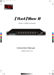
1
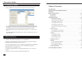
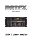
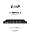
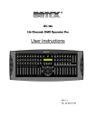
LIGHT OPERATOR
1
1
3
4
5
6
CHASES
2
3
4
1
2
3
4
5
6
7
8
5
6
7
8
2
3
FIXTURE SELECTOR 1-8
SHOW 1-8 Record Mode: Manual/Auto/Semi Auto
2
COLOUR PRESETS
1
4
Green
Red
Blue
Amber
SPEED
Cool
FADE
Warm
STROBE
Speed
MASTER
Master
10
10
Mode/Lib
Manual
5
10
10
10
10
0.1s
10
10m
10
Music
Auto
6
7
7
8
8
8
8
8
8
8
8
8
8
6
6
6
6
6
6
6
6
4
4
4
4
4
4
4
4
2
2
2
2
2
2
2
0
0
0
0
0
0
0
2
60m
0
0s
Botex LED Commander
USER MANUAL
24-004-2723-00 Rev1.0
Fn /Record
TAP/Step
Strobe/Delete
Black Out
Technical Specifications
Adapter (Included) .................................... AC230V 50Hz for power input
DC9V 500mA for power output
Power Input ......................................................... DC9-12V, 300mA min.
DMX IN .......................................................... 3PIN male XLR connector
DMX OUT ......................................... 3PIN female XLR connector (2pcs)
Audio Input ........................................................... Line input 0.1V-1Vpp
Dimensions .................................... 310mm(L) x 147mm(W) x 62.4mm(H)
Weight ....................................................................................... 1600g
20
Operation Guide
5.3.Configuring a SHOW
6. Click "EditShow" icon to edit and configure each of the 8 shows.
Table of Contents
Introduction ........................................................................... 1
Safety Information & Maintenance .......................................... 2
Features ................................................................................. 3
Basic Control Parts ............................................................ 4~6
Front Panel .............................................................................. 4~5
Rear Panel ................................................................................... 6
Operation Guide ............................................................... 7~19
1. LED Fixture Library ............................................................ 7~10
1.1 Patching a LED Fixture ......................................................... 7
1.2 Adding a LED Fixture ............................................................ 8
1.3 Editing a LED Fixture ............................................................ 9
1.4 Deleting a LED Fixture .......................................................... 9
6.1 Select the Show to configure by using the drop down menu in the
top right corner of the screen. Set the base address of Light Operator
in the DMX address field. Set fade time in the "Fade Time" field.
6.2 Assign scenes to the selected show using the ">", "Insert" and "<"
icons.
6.3 Click "Download to keypad" icon to save a configured show to the
Light Operator.
1.5 Initializing LED Fixture Library ............................................. 10
1.6 Exit .................................................................................... 10
2. Color Preset ...................................................................... 11~12
2.1 Creating a Color Preset ........................................................ 11
2.2 Deleting a Color Preset ........................................................ 12
3. Chase ............................................................................... 13~15
3.1 Editing a Chase ................................................................. 13
3.2 Deleting a Chase ................................................................ 14
6. About Updating
3.3 Running a Chase ................................................................ 15
4. Editing a Scene ...................................................................... 16
1. Obtain a file named "LightOpPro.scn" from BOTEX .
2. Power off Light Operator. Then hold on pressing "Fn/Record" button
and "Mode/Lib" button and power on the unit.
3. Connect Light Operator to your computer with USB cable via USB port.
4. Run the program "ART-16.exe". Then use EditShow function to
download the file "LightOpPro.scn".
5. Unplug the USB cable after completing download. Then, power off
the unit.
6. Power on the unit. The unit completes updating now.
19
5. Show ................................................................................ 17~18
5.1 Recording DMX signal ......................................................... 17
5.2 Running a SHOW ................................................................ 18
5.3 Configuring a SHOW ........................................................... 18
6. About Updating ...................................................................... 19
Technical Specifications ...................................................... 20
Introduction
Operation Guide
5.2. Running a SHOW
Thank you for selecting Light Operator from BOTEX. The Light Operator is a
prominent professional LED controller, as well as a conventional DMX
controller. This controller allows users to easily manipulate various LED
fixtures via simple to use buttons and faders. The Light Operator puts
programming, playback and live manipulation of Scenes and Chases at your
fingertips.
Fn /Record
1. To exit Programmable state, press and hold
down the "Fn/Record" button for about 5 seconds
until the LED indicator next to "Fn/Record" button
blacks out.
Unpacking
Every unit has been thoroughly tested and carefully packed before shipment.
Unpack the shipping carton and inspect thoroughly, saving the carton and all
packing materials for possible use later.
Check carefully and make sure your product is not damaged and that no
included accessory is missing. If your product appears to be damaged or
missing something, please do not use it and contact your local distributor
immediately.
SHOW
2. Press the SHOW button to choose a show
which you want to display. The unit can display
multiple shows in cycle.
5.3. Configuring a SHOW
About the manual
Read the instructions in this manual carefully and thoroughly, as they give
important information regarding safety during use and maintenance. Keep
this manual with the unit for consulting it in the future. If the unit is sold or
given to another operator, make sure that it always has its manual, to enable
the new owner to read about its operation and relative instruction.
1. Connect Light Operator to your computer with USB cable. If you first use
ART-16.exe, you need to install a USB drive program.
2. Launch ART-16.exe. The main screen displays as the following:
Update & Changes
Improvements and specifications in the design of the unit and manual are
subject to change without any prior written notice.
Copyright
All rights reserved. No part of this manual may be reproduced, in any form or
by any means, without authorized written permission.
3. Click "Open Flash" icon to select and display a flash file.
4. Click "Preview" icon to preview the flash file.
5. Click "FileConvert" icon to convert flash file with extension .swf into the
file with extension .scn which Light Operator can play directly .
1
18
Operation Guide
Safety Information & Maintenance
5. Show
Safety Information & Maintenance
5.1 Recording DMX Signal
Read this manual before powering or installing the fixture, and
follow the safety precautions listed below and observe all warnings
in this manual.
Fn /Record
1. To enable Programmable state, press and hold
down the "Fn/Record" button for about 5 seconds
until the LED indicator next to the "Fn/Record"
button is lit.
Be sure that the local power outlet matches that of the
required voltage for your unit.
To reduce the risk of fire or electrical shock, do not
expose this unit to rain or high levels of moisture.
SHOW
2. Press one of Show1-8 buttons to which you
want to record DMX signal.
Do not spill water or other liquids into or on your unit.
Do not open the unit as there are no user serviceable
parts inside.
3. Press the same Show button to choose record
mode. Then press "Fn/Record" button to enable
the record mode. In the process of recording, you
can press "Fn/Record" button to stop recording.
There are 3 record modes for user selection available in Manual mode, Auto
mode and Semi-Auto mode.
In Auto mode, while detected an initializing signal of "all zero", the rest
signal of "non-zero" will be recorded to the device automatically. While
detected the next signal of "all zero", all the indicators flash once, the
recording is complete.
In SEMI-AUTO mode, while detected an initializing signal of "all zero", the
rest signal of "non-zero" will be recorded to the device automatically. If you
want to stop recording, press SHOW button. While detected the next signal
of "all zero", all the indicators flash once, the recording is complete.
Do not dismantle or modify the unit, as this voids all
warranties.
Turn off the unit immediately in the event of malfunction.
Should you notice smoke or an unusual smell coming
from the equipment, please discontinue using it and
disconnect it from power immediately.
Do not attempt repairs. Repairs by unqualified people
could cause damage or faulty operation. Contact your
local authorized service center.
Unplug this unit when not used for long periods of time.
Clean only with dry cloth.
Handle this unit carefully. Any strong shock or vibration
may result in malfunction.
In MANUAL mode, while the device goes into the state of ready to record, manually
press the SHOW button and the device is processing record. Then press the same
SHOW button again to finish recording, all the indicators flash once, the recording
is complete and the device record all the DMX signal it receives.
Every SHOW is allowed to record up to 16 DMX segments. The total
time of record can exceed 1000 minutes.
17
2
Features
Principal Features
Professional LED controller, as well as DMX console.
Internal editable LED fixture library, each LED fixture having
maximal 8 programmable channels.
8 quick access Fixture buttons for controlling 8 different
LED fixtures, 64 channels in total.
Operation Guide
4. Editing a Scene
To create a scene, this unit must not be in the Programmable state. If this
unit is in Programmable state, hold on pressing "Fn/Record" button for about
5 seconds until the LED indicator beside the button blacks out to exit
Programmable state.
Fixture
1. Press any of Fixture1-8 buttons to choose a
fixture which you want to edit.
64 Color Presets, divided into 8 Banks.
8 programmable Chases, each can record up to 99 scenes.
2. Move the fader button, or select a color preset,
to edit a scene.
3 operation mode available in Auto mode, Music mode
and Manual mode.
Blackout master for shutting off all lighting fixtures.
Strobe function and Strobe frequency adjustable.
Strobe/Delete
Built-in 1G memory, being able to record up to 255 files.
3. Press "Strobe/Delete" button, if you want to
edit strobe effect, and the LED indicator beside
the button will flash repeatedly.
Additional 8 Shows, each can record 16 flash files which
are downloaded by record or from PC via USB port.
DMX 512 and DMX 1000K Output available.
LCD display for easy operation.
LED indicators.
Fn /Record
4. Press "Fn/Record" button and the LED
indicator beside the button is lit.
Audio input and built-in microphone for music synchronization.
USB port for connecting PC.
Power requirement of DC 9-12V, 300mA min.
5. Move "Strobe/Speed" fader button to change
strobe frequency between 0.1Hz and 20Hz.
3
16
Operation Guide
Basic Control Parts
3.3 Running a Chase
1. Press the Chase button to choose a chase.
The unit can choose 8 Chases simultaneously.
8
11
10
6
CHASE
7
To run a Chase, this unit must not be in the Programmable state. If this
unit is in Programmable state, hold on pressing "Fn/Record" button for
about 5 seconds until the LED indicator beside the button blacks out to
exit Programmable state.
9
Front Panel
Music
There are 3 modes for user selection available in
Manual mode, Music mode and Auto mode.
CPxx CSx
SENS: xxx
In Music mode, the rhythm triggers each step.
Users can press UP&DOWN buttons to increase
or decrease the sensitivity number.
2
CPxx CSx
FT: xxxxx
In Manual mode, press UP&DOWN buttons to
play the next or previous step. Press
"Fn/Record" button, then move fader6 button to
change the fade time between 0second and
10minutes.
"FT" means fadetime.
3
4
Auto
3. Press "Mode/Lib" button to choose running mode.
13
Mode/Lib
Manual
5 4
12
2. Press UP&DOWN button to change loop
number for the chase.
1
"SENS" means sensitive.
CPxx CSx
SP: xxxx
15
In Auto mode, the chase is played automatically.
Users can set speed by quickly pressing the
"Tap/Step" button twice. Alternatively, users can
press "Fn/Record" button, then move fader5
button to change the speed.
"SP" means speed.
4
Basic Control Parts
Front Panel
Operation Guide
3.1 Editing a Chase
1. SHOW buttons 1-8
Show buttons are used to play recorded flash files.
2. FIXTURE selectors 1-8
The Fixture selectors are used to select LED lighting fixtures for manual
control. Hold on pressing this button for 2s to see the patched LED fixture.
3.Colour Preset buttons 1-8
The Colour Preset buttons are used to select 64 color preset. Hold on
pressing this button for 2s to see and edit bank when playing a Chase.
4. UP / DOWN buttons
The UP / DOWN buttons are used to choose bank, scroll and adjust
desired levels during operation.
5. LCD screen
The LCD screen displays current information about the console state.
6. Chase buttons 1-8
Chase buttons are used to playback or store Chase.
7. Mode/Lib button
This button is used to choose operating mode in normal state and
to launch LED fixture library in edit state.
In Manual mode, hold on pressing this button for 2s to see Fade time.
In Music mode, hold on pressing this button for 2s to see sensitive.
In Auto mode, hold on pressing this button for 2s to see step speed.
8. TAP / Step button
This button is used to select step when editing a chase and set triggering
time in playing a chase.
Strobe/Delete
7. If you want to delete a step, press UP&DOWN
buttons to choose the undesired step. Then press
"Strobe/Delete" button to delete current step.
Users can store up to 99 steps per Chase. Every Chase has 8
built-in steps as factory setting.
3.2 Deleting a Chase
To delete a Chase, this unit must be in the Programmable state.
Hold on pressing the "Strobe/Delete" button,
simultaneously, press the Chase button to
choose the chase which you wan to delete, until
all the LED indicators flash repeatedly 3 times.
CHASE
Strobe/Delete
+
9. Fn/Record button
Hold on pressing Fn/Record button for 5s to enter/exit programmable state.
Tapping this button to switch between the two functions of Faders5-8.
10. Blackout button
Blackout button is used to take all DMX value to 0.
11. Strobe/ Delete button
This button is used to choose Strobe function and to delete undesired
items in programmable state.
In the state of Strobe, hold on pressing this button for 2s to see frequency.
12. LED indicators
These indicators show the current operation.
13. Faders 1-8
Faders 1-8 are used to adjust desired value.
5
14
Operation Guide
Basic Control Parts
3. Chase
Rear Panel
3.1 Editing a Chase
Serial Number:
To create a Chase, this unit must be in the Programmable state.
Patent Pending
CHASE
Made in P.R.C.
RoHS
1. Press Chase button to select the Chase which
you want to configure.
A
DMX OUT
1
1=Ground
2=Data3=Data+
B
2
DMX IN
3
AUDIO
USB
Line Input 0.1V-1Vp-p
4
5
DC IN:
9-12V,
300mA min.
POWER
6
7
1. DMX OUT A
3pin XLR female connector to send DMX data to fixtures.
2. DMX OUT B
Fixture
2. Press Fixture button to choose a fixture which
you want to edit.
3pin XLR female connector to send SHOW data or output
Preview function of PC software.
3. DMX IN
3pin XLR male connector to receive DMX data.
3. To edit a scene, you can move the fader buttons,
or choose a Color Preset, or input DMX signal.
4. USB port
Used to connect PC to edit SHOW.
5. Audio in
Fn /Record
4. Press the "Fn/Record" button to record the
current step and all the LED indicators flash
repeatedly 3 times.
Line input 0.1V-1Vp-p.
6. Power switch
Used to power on/off the unit.
7. DC IN
5. Repeat step3~4 to record more steps.
CPxx CSxx
Mxx Sxx
DC 9-12V, 300mA min.
6. If you want to insert a step, press "Tap/Step"
button and the LCD displays as the left figure.
CPxx means Color Preset.
CSxx menas Chase xx.
Mxx means total steps of the Chase.
Sxx menas current step.
Press UP & DOWN buttons to choose the location
to which you want to insert the step. Then repeat
step3~4, a step is insert into current step.
13
6
Operation Guide
1. LED Fixture Library
All the modification to LED fixture library can be done only in Programmable
state. To enable Programmable state, you simply take the following steps:
Fn /Record
1. Press and hold down the "Fn/Record" button for
about 5 seconds until the LED indicator next to the
"Fn/Record" button blinks. The device is engaged in
programmable state.
2. Press the "Mode/Lib" button to enter LED fixture
Library.
Operation Guide
2.2 Deleting a Color Preset
To delete a color preset, this unit must be in the Programmable state.
To delete an undesired color preset, hold on
pressing "Strobe/Delete" button, simultaneously
press the Color Preset button. Then all the LED
indicators flash repeatedly 3 times to confirm the
setting.
Strobe/Delete
Color Preset
+
1.1 Patching a LED Fixture
Fix Lib
1.Patch
1. Press UP & DOWN buttons to scroll the menu on
LCD display and select the submenu "1.Patch".
Light Operator has 64 built-in Color Presets, divided into 8 banks.
Fn /Record
2. Press the "Fn/Record" button to start to patch.
REBEL1
CW - - - - - -
3. Press UP & DOWN buttons to select the desired
LED fixture. Then press the fixture button to which
you want to patch the LED.
4. If you want to choose other LEDs, repeat step3.
Mode/Lib
5. When you are satisfied with the patch, press the
"Mode/Lib" button to exit.
7
12
Operation Guide
Operation Guide
1.2 Adding a LED Fixture
2. Color Preset
To add a LED fixture, this unit must be in the Programmable state.
All the modification to Color Preset can be done only in Programmable state.
To enable Programmable state, you simply follow the step listed below:
Fix Lib
2.Add
Fn /Record
Press and hold down the "Fn/Record" button for
about 5 seconds until the LED indicator next to
"Fn/Record" button blinks.
2.1 Creating a Color Preset
Fixture
In "2.Add" menu, user can press Up&Down buttons to
navigate to different submenus.
Fix Name
Userfix
2. M ove the fader or import DMX signal to edit a
scene. Then, p ress "Fn/Record" button to record
the current value.
Chan1:
Red
3. Press UP & DOWN buttons to choose banks.
4. Press a Color Preset button to which you wish
to store the scene, and all the LED indicators
flash repeatedly 3 times to confirm your setting.
5. Repeat step1~4 to record more scenes to preset.
11
Modify:
Userfx
2. Press "Fn/Record" button firstly.
Secondly, move fader button 1-6 to
change the fixture name. Then press
"Fn/Record" button to confirm the
setting.
Modify:
3
3. Press "Fn/Record" button firstly.
Secondly, move fader1 button to
choose the channel number. Then
press "Fn/Record" button to confirm
the setting.
1. Choose the Fixture that you wish to edit, and
the LED indicator next to the fixture button is lit.
Total Ch
3
Color Preset
1. Press UP & DOWN buttons to scroll to the menu
"2.Add". Then press "Fn/Record" button to add a fixture.
Modify:
Red
4. Press "Fn/Record" button firstly.
Secondly, move one of fader1-6
buttons to change the color.Then
press "Fn/Record" button to confirm
the setting.
5. Repeat step4 to configure the color of other channels.
Save &
Exit
Save-Rec
Quit-Lib
6. Press the "Fn/Record" button to save and exit the
configurations.
Alternatively, user can press "Mode/Lib" button. Then
press "Fn/Record" button to save the configurations, or
press "Mode/Lib" button to give up the configurations.
8
Operation Guide
Operation Guide
1.3 Editing a LED Fixture
1.5 Initializing LED Fixture Lib.
To edit a LED fixture, this unit must be in the Programmable state.
To add a LED fixture, this unit must be in the Programmable state.
Fix Lib
3.Edit
REBEL1
CW - - - - - -
1. Press UP & DOWN buttons to scroll to the
menu "3.Edit". Then press "Fn/Record" button
to enter edit menu.
Fix Lib
5.Initia
2. Press Up&Down buttons to choose the LED
fixture which you want to edit. Then press the
"Fn/Record" button to start to edit the LED fixture.
Fn /Record
1. Press UP & DOWN buttons to scroll to the
menu "5.Initia".
2. Then press "Fn/Record" button initialize the
LED fixture library, and all the LED indicators
flash repeatedly 3 times to confirm the setting.
3. Repeat step 2~6 of "1.2 Adding a LED Fixture"
to complete the edit.
1.4 Deleting a LED Fixture
1.6 Exit
To delete a LED fixture, this unit must be in the Programmable state.
There are two ways available for users to exit LED fixture Lib.
Fix Lib
4.Delete
1. Press UP & DOWN buttons to scroll to the
menu "4.Delete". Then press "Fn/Record" button
to enable the delete function.
Mode/Lib
<
>
Press "Mode/Lib" button to exit LED fixture library.
2. Press UP&DOWN buttons to select the LED
fixture which you want to delete.
Fix Lib
6.Exit
Strobe/Delete
Alternatively, press UP & DOWN buttons to scroll
to the menu "6.Exit". Press "Fn/Record" button to
exit LED fixture library.
3. Press "Strobe/Delete" button to delete the
undesired LED fixture, and all the LED indicators
flash repeatedly to confirm the setting.
4. Press "Fn/Record" button to exit current menu.
9
10