1
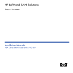
HP StorageWorks
P4000 VSA user guide
Abstract
This guide provides information about designing a virtual SAN using the HP StorageWorks P4000 VSA. Topics
include hardware configuration for the servers that host the VSAs, virtual network design, and best practices for
using VSAs with the P4000 SAN solution. The intended audience is system administrators who are using VSAs
as the storage platform for the P4000 SAN.
Part number: TA688-96014
Third edition: March 2010
Legal and notice information
© Copyright 2009-2010 Hewlett-Packard Development Company, L.P.
Confidential computer software. Valid license from HP required for possession, use or copying. Consistent with FAR 12.211
and 12.212, Commercial Computer Software, Computer Software Documentation, and Technical Data for Commercial Items
are licensed to the U.S. Government under vendor's standard commercial license.
The information contained herein is subject to change without notice. The only warranties for HP products and services are set
forth in the express warranty statements accompanying such products and services. Nothing herein should be construed as
constituting an additional warranty. HP shall not be liable for technical or editorial errors or omissions contained herein.
Contents
1 Designing a virtual SAN ..................................................................... 7
Getting started ........................................................................................................................... 7
Designing your virtual SAN .......................................................................................................... 7
Configuration requirements .................................................................................................... 7
Best practices ...................................................................................................................... 8
Unsupported configurations ............................................................................................. 9
Hardware design for VSA ............................................................................................................ 9
CPU ................................................................................................................................... 9
Memory .............................................................................................................................. 9
Controllers and hard drives .................................................................................................. 10
Network adapters .............................................................................................................. 10
Virtual network design ............................................................................................................... 10
Using VSAs with HP LeftHand Storage Solutions ............................................................................ 11
Cloning VSAs .................................................................................................................... 11
Running SAN/iQ managers on physical platforms .................................................................. 11
Locating VSA running managers on separate physical platforms ............................................... 11
Managing performance impact of mixing platforms in clusters .................................................. 11
Adding storage capacity to a VSA .............................................................................................. 11
Create disks using VMware ................................................................................................. 12
Requirements ............................................................................................................... 12
Add disks to RAID .............................................................................................................. 12
Changing the disk size on the SAN ................................................................................ 13
Sample configurations ............................................................................................................... 13
Single node configuration ................................................................................................... 13
Two-node configuration ....................................................................................................... 14
Three-node-plus configuration .............................................................................................. 14
2 Support and other resources .............................................................. 17
Contacting HP ..........................................................................................................................
Subscription service ............................................................................................................
New and changed information in this edition ...............................................................................
Related information ...................................................................................................................
HP websites .......................................................................................................................
Typographic conventions ...........................................................................................................
HP product documentation survey ...............................................................................................
17
17
17
17
18
18
19
Glossary ............................................................................................ 21
P4000 VSA user guide
3
Figures
1 Example of a virtual SAN using the VSA ...................................................................... 7
2 Example virtual network for a virtual SAN .................................................................. 10
3 Two additional disks; one added to RAID, one still powered off .................................... 12
4 Single node configuration ........................................................................................ 14
5 Two-node configuration ........................................................................................... 14
6 Three-node-plus configuration ................................................................................... 15
4
Tables
1 Memory requirements for VSA disks ............................................................................ 7
2 Memory requirements for VSA disks .......................................................................... 12
3 Document conventions ............................................................................................. 18
P4000 VSA user guide
5
6
1 Designing a virtual SAN
The HP LeftHand P4000 VSA enables full featured use of the SAN/iQ software in a virtualized
environment. When deployed correctly, HP LeftHand Networks virtual SANs are scalable, highly
available, and fully redundant.
Figure 1 Example of a virtual SAN using the VSA
.
Getting started
Find detailed instructions for properly installing and configuring the VSA in both the VMware VI Client
and the SAN/iQ software in the Quick Start Guide for the VSA. The VSA Quick Start Guide is available
in PDF format and is installed in the Documentation subdirectory with the HP LeftHand Centralized
Management Console program files.
Designing your virtual SAN
The design of your virtual SAN affects both its performance and its reliability for production use. Use
the concepts and practices in this manual when installing and managing your virtual SAN to ensure
optimal performance and reliability.
Configuration requirements
The following configuration requirements are prerequisites for HP LeftHand Networks to support your
virtual SAN for production use.
• A qualified server running VMware ESX Server 3.0.x. Qualified servers are listed in VMware ESX
Server 3.0.x systems compatibility guide, which can be found at
http://www.vmware.com/resources/compatibility/search.php.
• Reserved memory based on total disk capacity, as listed in Table 1 on page 7.
Table 1 Memory requirements for VSA disks
Total capacity of all installed disks
Requires at least this much memory
< 500 GB
384 MB
500 GB to 4.5 TB
1 GB
4.5 TB to 9 TB
2 GB
P4000 VSA user guide
7
Total capacity of all installed disks
Requires at least this much memory
9 TB to 10 TB
3 GB
• A single virtual CPU with at least 2000 MHz reserved.
• A connection to a virtual switch with at least a Gigabit network connection.
• Virtual disk(s) with 5 GB to 2 TB (2047 sectors) of space per disk located on internal disk storage,
or direct attached storage that is not accessible from more than one physical server. (Note that
the SAN/iQ OS consumes a small amount of the available space.) The first virtual disk must be
connected to SCSI address 1:0.
• All virtual disks for the VSA must be configured as independent and persistent to prevent VM
snapshots from affecting them.
• The VMFS datastore for the VSA must not be shared with any other VMs.
• Two or more VSAs on separate physical servers with 2-way replication, and a Failover Manager
is the minimum configuration for high availability with automatic failover.
Two or more VSAs on separate physical servers can be clustered with a Virtual Manager for
manual failover.
Best practices
Other configuration recommendations are useful to improve the reliability and performance of your
virtual SAN. Consider implementing as many of these best practices as possible in your virtual SAN
environment.
Each VSA should meet the following conditions, if possible.
• Have a virtual switch comprised of dual Gigabit Ethernet or more. Providing network redundancy
and greater bandwidth improves both performance and reliability.
• Be located on the same virtual switch as the VMkernel network used for iSCSI traffic. This allows
for a portion of iSCSI IO to be served directly from the VSA to the iSCSI initiator without using a
physical network.
• Be on a virtual switch that is separate from the VMkernel network used for VMotion. This prevents
VMotion traffic and VSA IO traffic from interfering with each other and affecting performance.
• Be configured to start automatically and first, and before any other virtual machines, when the
ESX Server on which it resides is started. This ensures that the VSA is brought back online as soon
as possible to automatically re-join its SAN/iQ cluster.
• Use redundant RAID for the underlying storage of a VSA in each ESX Server to prevent single disk
failures from causing VSA node failure. Do not use RAID0.
NOTE:
See the HP StorageWorks P4000 SAN Solution User Manualfor detailed information about using
RAID for individual server-level data protection. The HP StorageWorks P4000 SAN Solution User
Manual is available in PDF format and is installed in the Documentation subdirectory with the HP
LeftHand Centralized Management Console program files. You can also find the information in
the online Help, available from the Help menu and the context-sensitive Help buttons on each
window in the HP LeftHand Centralized Management Console.
8
Designing a virtual SAN
Unsupported configurations
Some configurations that are possible using VMware ESX and the VSA are specifically not supported
for production use at this time.
HP LeftHand Networks does not support the following configurations or procedures.
• More than 2 NICs configured on the VSA.
• NIC bonding using the CMC within the VSA itself. (NIC bonding is a best practice in the ESX
server.)
• Use of any shared storage as the data location of the VSA. This includes shared DAS, Fibre
Channel, iSCSI, and NAS.
• Use of VMware snapshots, VMotion, HA, or DRS on the VSA itself.
• Use of any ESX server configuration that VMware does not support.
• Booting ESX off of a VSA cluster.
• Extending the data (SCSI 1:0) vmdk of the VSA while in a SAN/iQ cluster.
• Co-location of a VSA and other virtual machines on the same physical platform without reservations
for the VSA CPU and memory.
• Co-location of a VSA and other virtual machines on the same VMFS datastore.
• Use of VSAs on other VMware platforms such as VMware Server, Workstation, or Player.
Hardware design for VSA
The hardware platform used for a virtual SAN affects the capacity, performance, and reliability of
that virtual SAN. The hardware features listed below affect the VSA configuration.
•
•
•
•
CPU
Memory
Controllers and Hard Disk Drives
Network Adapters
CPU
Because the CPU of the VSA must be reserved, platforms that will host a VSA and other VMs should
be built with more processor cores to accommodate the additional VMs. Multi-core processors with
at least 2GHz per core should be used so that a single core with at least 2GHz can be reserved for
the VSA. All additional cores are then available for use with other VMs, thereby avoiding resource
contention with the virtual SAN. For example, a platform with two dual core processors could host a
VSA and use 3 cores to share for other VMs.
Memory
Similarly the memory of the VSA must be reserved. For platforms that will host a VSA and other VMs,
build in additional memory to accommodate the additional VMs. Assuming the hypervisor and
management applications will use less than 1GB, memory beyond 2GB is available to use with other
VMs, again avoiding resource contention with the virtual SAN. For example, assuming a VSA using
less than 4.5 TB, a platform with 10GB of RAM could host a VSA and use 8GB of memory to share
for other VMs.
P4000 VSA user guide
9
Controllers and hard drives
The internal disk controller and actual hard disk drives of a platform affect the capacity and IO
performance of the VSA. Ideally VSAs should use storage that is hosted by many SAS or SCSI drives.
If you are designing a new server that will host VSAs, you should incorporate the following
recommendations.
• Use as many hard drives as the platform will allow and prefer faster rotation speeds. The more
hard drives and the faster their rotation speed, the more IOPS, and better performance.
• Select controllers with protected write cache.
Network adapters
The number of network adapters available in a platform affects your options for configuring virtual
switches. VSAs that will have a dedicated ESX Server platform only need 2 Gigabit network adapters.
Platforms that will host VSAs and other virtual machines should have at least 4 Gigabit network
adapters so that two adapters can be dedicated to the VSA and iSCSI traffic.
Virtual network design
The virtual switch that is used for VSA should be at least a redundant Gigabit network, and should
be shared with the iSCSI VMkernel network. If possible, an additional virtual switch with a VMkernel
network for VMotion should be configured in order to separate VMotion traffic from iSCSI traffic. If
enough network connections are available, the virtual network shown is an ideal example for a virtual
SAN.
Figure 2 Example virtual network for a virtual SAN
.
Performance and reliability can be improved even further by using more than two Gigabit adapters
in the iSCSI and VSA virtual networks.
10
Designing a virtual SAN
Using VSAs with HP LeftHand Storage Solutions
VSAs and physical platforms can be mixed in SAN/iQ management groups and clusters. When
mixing virtual and physical platforms, and mixing differently configured VSAs, you should take the
following requirements and guidelines into consideration.
Cloning VSAs
To clone a VSA, you must do so while the VSA is still in the Available pool, before you add it to a
management group. Cloning a VSA after it is in a management group is not supported.
NOTE:
Configure the first VSA for RAID, Alerts, SNMP and Networking. Then create your clone with the
hardware settings already configured.
Running SAN/iQ managers on physical platforms
When possible, locate all managers in a management group on physical platforms instead of VSAs,
and ideally on the fastest platforms in the management group. While VSAs can run managers, physical
platforms provide better performance and a lower likelihood that they will be rebooted for administrative
reasons.
Locating VSA running managers on separate physical platforms
If VSAs are running managers, ensure that those VSAs reside on separate physical platforms. Otherwise,
rebooting a single physical platform could cause a loss of quorum in the management group.
Managing performance impact of mixing platforms in clusters
Mixing VSAs and physical platforms in a SAN/iQ cluster yields unpredictable performance. Mixing
VSAs built from different hardware in the same cluster also yields unpredictable performance. Typically
the overall performance of the cluster is close to the aggregate average of the storage nodes in the
cluster.
Additionally, you may perceive performance degradation if a faster VSA fails, thereby causing volumes
to fail over to a slower VSA. Such performance degradation is normal in a mixed cluster.
Adding storage capacity to a VSA
Add storage capacity to a VSA by adding up to 4 additional virtual disks for a total of 5 disks. Note
that the additional capacity on the VSA will operate according the same rules for physical storage
nodes in a cluster; that is, the VSA will operate at a capacity equal to that of the smallest capacity
storage node in the cluster.
The following steps describe how to add disks after the VSA has been added to a management group
and cluster. However, you can add the disks to the VSA when you first configure it in VMware, before
you use it for clustered storage.
P4000 VSA user guide
11
Create disks using VMware
Create up to 4 additional disks for a VSA.
Requirements
• Minimum size - 5 GB
• Maximum size - 2 TB
• Created sequentially from SCSI 1:1 through SCSI 1:4. This assumes that the first disk has already
been created and assigned to SCSI 1:0.
Creating a disk
1. Power off the VSA.
2.
Using either VMware Server or VI Client, add from 1 to 4 disks to the VSA.
3.
Assign each disk to the next sequential SCSI address, from SCSI 1:1 through SCSI 1:4.
4.
Increase memory based on the total capacity of the VSA, according to the requirements in Table
2 on page 12.
Table 2 Memory requirements for VSA disks
5.
Total capacity of all installed disks
Requires at least this much memory
< 500 GB
384 MB
500 GB to 4.5 TB
1 GB
4.5 TB to 9 TB
2 GB
9 TB to 10 TB
3 GB
Power on the VSA when you have finished adding disks.
Add disks to RAID
1.
In the CMC, navigate to the VSA.
2.
Select the Storage configuration category and select the Disk Setup tab.
The new disks appear as Uninitialized.
Figure 3 Two additional disks; one added to RAID, one still powered off
.
12
Designing a virtual SAN
3.
Select the disk(s) you want to add to RAID.
Disks must be added to RAID sequentially. You cannot add disk 3 to RAID if disk 2 has not been
added.
4.
Right-click and select Add Disk to RAID.
Adding the disk to RAID automatically powers it on.
Changing the disk size on the SAN
Use the VI Client if you want to change the disk size of a VSA that is currently in your HP LeftHand
Storage Solution.
You must follow these steps in the sequence listed or the VSA will be unable to participate in a
management group.
1.
Remove the VSA from the management group.
2.
Using the VI Client, power off the VSA.
3.
Select the VSA and select Edit Settings to open the Virtual Machine Properties window.
4.
Select the hard disk that is on the port SCSI 1:0 and click Remove.
5.
Click Add and use the Add Hardware Wizard to add a new hard disk of the desired size to port
SCSI 1:0.
See detailed instructions in the section “Configure a data disk” in the VSA Quick Start Guide,
installed in the Documentation directory with the HP LeftHand Centralized Management Console
files.
6.
Power on the VSA.
7.
In the HP LeftHand Centralized Management Console, reconfigure RAID.
8.
Add the VSA to a new or existing management group and cluster.
9.
Reconfigure RAID on the VSA.
Sample configurations
Some sample configurations and their uses and benefits are described below.
Single node configuration
A single node configuration is useful for implementing a simple iSCSI target that can scale up to a
redundant iSCSI SAN of any size. A single node configuration has only the elements listed.
•
•
•
•
One VSA
A single management group
A single cluster
Running a single manager
P4000 VSA user guide
13
Figure 4 Single node configuration
.
Two-node configuration
A two-node configuration is the smallest possible redundant configuration. Automatic failover between
nodes requires a failover manager. A two-node configuration includes the elements listed.
• Two VSAs in a single management group
• A single cluster
• Two managers
• A Failover Manager added to the management group
NOTE:
For more information, see “Failover Manager Overview” in the HP StorageWorks P4000 Multi-Site
HA/DR Solution Pack User Manual, installed with the HP LeftHand Centralized Management
Console as a PDF in the Documentation folder.
Figure 5 Two-node configuration
.
Three-node-plus configuration
All configurations greater than two nodes can be redundant, and do not require a Virtual Manager
or Failover Manager. A configuration greater than two nodes includes the items listed.
• 3 or more nodes in a management group
• Multiple clusters with as many VSAs as desired in each cluster
• Running either 3 or 5 managers
14
Designing a virtual SAN
Figure 6 Three-node-plus configuration
.
P4000 VSA user guide
15
16
Designing a virtual SAN
2 Support and other resources
Contacting HP
For worldwide technical support information, see the HP support website:
http://www.hp.com/support
Before contacting HP, collect the following information:
• Product model names and numbers
• Technical support registration number (if applicable)
• Product serial numbers
• Error messages
• Operating system type and revision level
• Detailed questions
Subscription service
HP recommends that you register your product at the Subscriber's Choice for Business website:
http://www.hp.com/go/e-updates
After registering, you will receive email notification of product enhancements, new driver versions,
firmware updates, and other product resources.
New and changed information in this edition
The following additions and changes have been made for this edition:
• The following information has been updated:
• Branding change to book title
• A new Support and Other Resources chapter has been added.
• The Preface was removed
Related information
The following documents [and websites] provide related information:
• HP StorageWorks P4000 SAN Solution User Manual
• HP StorageWorks P4000 Multi-Site HA/DR Solution Pack User Manual
You can find these documents from the Manuals page of the HP Business Support Center website:
http://www.hp.com/support/manuals
In the Storage section, click Disk Storage Systems and then select P4000 SAN Solutions.
P4000 VSA user guide
17
HP websites
For additional information, see the following HP websites:
•
•
•
•
•
•
http://www.hp.com
http://www.hp.com/go/storage
http://www.hp.com/service_locator
http://www.hp.com/support/manuals
http://www.hp.com/support/downloads
http://www.hp.com/storage/whitepapers
Typographic conventions
Table 3 Document conventions
Convention
Element
Blue text: Table 3
Cross-reference links and e-mail addresses
Blue, underlined text: http://www.hp.com
Website addresses
• Keys that are pressed
Bold text
Italic text
• Text typed into a GUI element, such as a box
• GUI elements that are clicked or selected, such as menu
and list items, buttons, tabs, and check boxes
Text emphasis
• File and directory names
Monospace text
• System output
• Code
• Commands, their arguments, and argument values
Monospace, italic text
Monospace, bold text
• Code variables
• Command variables
Emphasized monospace text
CAUTION:
Indicates that failure to follow directions could result in damage to equipment or data.
IMPORTANT:
Provides clarifying information or specific instructions.
18
Support and other resources
NOTE:
Provides additional information.
TIP:
Provides helpful hints and shortcuts.
HP product documentation survey
Are you the person who installs, maintains, or uses this HP storage product? If so, we would like to
know more about your experience using the product documentation. If not, please pass this notice to
the person who is responsible for these activities.
Our goal is to provide you with documentation that makes our storage hardware and software products
easy to install, operate, and maintain. Your feedback is invaluable in letting us know how we can
improve your experience with HP documentation.
Please take 10 minutes to visit the following web site and complete our online survey. This will provide
us with valuable information that we will use to improve your experience in the future.
http://www.hp.com/support/storagedocsurvey
Thank you for your time and your investment in HP storage products.
P4000 VSA user guide
19
20
Support and other resources
Glossary
The following glossary provides definitions of terms used in the SAN/iQ software and the HP LeftHand
SAN Solution.
active monitoring
Active monitoring tracks the health of the storage node using notifications such
as emails, alerts in the CMC, and SNMP traps.
acting primary
volume
The remote volume, when it assumes the role of the primary volume in a failover
scenario.
Active-Passive
A type of network bonding which, in the event of a NIC failure, causes the logical
interface to use another NIC in the bond until the preferred NIC resumes
operation. At that point, data transfer resumes on the preferred NIC.
Adaptive Load
Balancing
A type of network bonding in which the logical interface performs load balancing
of data transmission.
add-on application
An additional feature purchased separately from the SAN/iQ software.
application-managed
snapshot
Snapshot of a volume that is taken while the application that is serving that
volume is quiesced. Because the application is quiesced, the data in the snapshot
is consistent with the application's view of the data. That is, no data was in flight
or cached waiting to be written.
authentication
group
For release 7.0 and earlier, identifies the client or entity accessing the volume.
Not used in release 8.0 and later.
Auto Discover
A feature in the CMC that automatically searches for storage nodes on the subnet
the CMC is connected to. Any storage nodes it discovers appear in the navigation
window on the left side of the CMC.
Bond0
Interface created for network interface failover and only appears after configuring
for failover.
bonding
Combining physical network interfaces into a single logical interface.
boot device
Compact flash cards from which the storage node boots up. Also known as
disk-on-modules or DOMs.
CHAP
Challenge-Handshake Authentication Protocol (CHAP) is a standard authentication
protocol.
clone point
The snapshot that has two or more volumes associated with it. A clone point is
created when a SmartClone volume is created from a snapshot or from snapshot
temporary space.
CLI
Command-line interface for the SAN/iQ software.
cluster
A cluster is a grouping of storage nodes that create the storage pool from which
you create volumes.
P4000 VSA user guide
21
CMC
Centralized Management Console. See HP LeftHand Centralized Management
Console.
communication
mode
The unicast communication among storage nodes and application servers.
community string
The community string acts as an authentication password. It identifies hosts that
are allowed read-only access to the SNMP data.
Configuration
Summary
The Configuration Summary displays an overview of the volumes, snapshots,
storage nodes, and iSCSI sessions in the HP LeftHand Storage Solution. It provides
an overview of the storage network broken out by management groups.
data center
Also known as a “Site.” A data center is a physical location in your environment
where application servers, SAN storage and network equipment reside. In the
SAN/iQ Multi-Site software, a data center is typically referred to as a site.
disaster recovery
site
Similar to a secondary site, the disaster recovery site is used to operate the SAN
in the event of a disaster.
disk status
Whether the disk is
•
•
•
•
Active - on and participating in RAID
Uninitialized or Inactive - On but not participating in RAID
Off or Missing - Not on
DMA Off - disk unavailable due to faulty hardware or improperly seated in
the chassis
DSM
Device Specific Module
DSM for MPIO
The HP LeftHand Networks vendor-specific DSM that interfaces with the Microsoft
MPIO framework.
failback
After failover, the process by which you restore the primary volume and turn the
acting primary back into a remote volume.
failover
The process by which the user transfers operation of the application server over
to the remote volume. This can be a manual operation, a scripted operation, or
VMware enabled.
Failover Manager
A specialized manager running as a VMware appliance that allows you to place
a quorum tie-breaker node into a 3rd location in the network to provide for
automated failover/failback of the Multi-Site SAN clusters. The Failover Manager
is designed to run on VMware ESX Server, VMware Server and VMware Player.
It is installed on hardware separate from the SAN hardware.
failover recovery
After failover, the process by which the user chooses to fail back to the primary
volume or to make the acting primary into a permanent primary volume.
frame size
The frame size specifies the size of data packets that are transferred over the
network.
full provisioning
Full provisioning reserves the same amount of space on the SAN as is presented
to application servers.
22
Glossary
ghost storage node
When using Repair Storage Node, a “ghost” storage node acts as a placeholder
in the cluster, keeping the cluster intact, while you repair or replace the storage
node.
Graphical Legend
Describes all the icons used in the CMC
• Items tab - displays the icons used to represent virtual items displayed in the
CMC
• Hardware tab - displays the icons that represent the physical storage units.
hardware reports
Hardware reports display point-in-time statistics about the performance and health
of the storage node, its drives, and configuration.
hostname
The hostname on a storage node is the user-definable name that displays below
the storage node icon in the network window. It is also visible when the users
browse the network.
HP LeftHand
Centralized
Management
Console
Management interface for the SAN/iQ software.
ID LED
LED lights on the physical storage node so that you can find that node in a rack
[NSM 260 only].
iSCSI
Internet SCSI. The iSCSI protocol defines the rules and processes for transporting
SCSI (block-level) data over a TCP/IP network.
iSCSI load
balancing
Improves iSCSI performance and scalability by distributing iSCSI sessions for
different volumes evenly across storage nodes in a cluster.
license keys
A license key registers a storage node for add-on applications. Each storage
node requires its own license key.
Link Aggregation
Dynamic Mode
A type of network bonding in which the logical interface uses both NICs
simultaneously for data transfer.
log files
Log files for the storage node are stored both locally on the storage node and
are also written to a remote log server.
logical site
This site is on an isolated network and power connection than the other sites.
However, it can be in the same physical location as one of the real sites. Also,
a site for a Failover Manager.
management
group
A collection of one or more storage nodes which serves as the container within
which you cluster storage nodes and create volumes for storage.
managers
Manager software runs on storage nodes within a management group. You start
managers on designated storage nodes to govern the activity of all of the storage
nodes in the group.
MIB
The Management Information Base provides SNMP read-only access to the
storage node.
monitored
variables
Variables that report health status of the storage node. These variables can be
monitored using alerts, emails, and SNMP traps.
P4000 VSA user guide
23
Multi-Site cluster
A cluster of storage that spans multiple sites (up to 3). A Multi-Site cluster must
meet at least one of the following conditions:
• Contain storage nodes that reside in two or more sites
• Contain storage nodes that span subnets
• Contain multiple VIPs. The cluster can have a single site, and the multiple VIPs
make it a multi-site cluster.
network RAID
Synchronous replication, mirroring or parity protection on a volume-by-volume
basis. Protecting data for a volume across all storage nodes in the cluster.
Network RAID-10, 10+1 or 10+2 is required to protect data in an HP LeftHand
SAN solution.
network window
Graphically depicts the status of each storage node. Storage nodes on the network
are either available or part of a management group.
NTP
Network Time Protocol
parity
In RAID5, redundant information is stored as parity distributed across the disks.
Parity allows the storage node to use more disk capacity for data storage.
peer site
Absence of a primary site designation makes all the sites peer sites.
primary site
A site designation assigned by the administrator in the HP LeftHand Centralized
Management Console. A primary site is more important than a secondary site.
In this setup, you would run a majority of managers in the primary site. In a
two-site setup, this allows the primary site to stay online even if the network link
between the primary and secondary sites fails. Typically, the primary site has
majority/all of the application servers. In configurations that do not designate a
primary site, the sites are referred to as “peer” sites.
original primary
volume
The primary volume that fails and then is returned to service.
overprovisioned
cluster
An overprovisioned cluster occurs when the total provisioned space of all volumes
and snapshots is greater than the physical space available on the cluster. This
can occur when there are snapshot schedules and/or thinly provisioned volumes
associated with the cluster.
point-in-time
snapshot
Snapshots that are taken at a specific point in time, but an application writing
to that volume may not be quiesced. Thus, data may be in flight or cached and
the actual data on the volume may not be consistent with the application's view
of the data.
preferred interface
A preferred interface is the interface within an active backup bond that is used
for data transfer during normal operation.
primary snapshot
A snapshot of the primary volume which is created in the process of creating a
remote snapshot. The primary snapshot is located on the same cluster as the
primary volume.
primary volume
The volume which is being accessed (read/write) by the application server. The
primary volume is the volume that is backed up with Remote Copy.
quorum
A majority of managers required to be running and communicating with each
other in order for the SAN/iQ software to function.
24
Glossary
RAID device
RAID (originally redundant array of inexpensive disks, now redundant array of
independent disks) refers to a data storage scheme using multiple hard drives
to share or replicate data among the drives.
RAID levels
Type of RAID configuration.
• RAID0 - data striped across disk set
• RAID1 - data mirrored from one disk onto a second disk
• RAID10 - mirrored sets of RAID1 disks
• RAID5 - data blocks are distributed across all disks in a RAID set. Redundant
information is stored as parity distributed across the disks.
• RAID50 - mirrored sets of RAID5 disks.
RAID quorum
Number of intact disks required to maintain data integrity in a RAID set.
RAID rebuild rate
The rate at which the RAID configuration rebuilds if a disk is replaced.
RAID status
Condition of RAID on the storage node
• Normal - RAID is synchronized and running. No action is required.
• Rebuild - A new disk has been inserted in a drive bay and RAID is currently
rebuilding. No action is required.
• Degraded - RAID is not functioning properly. Either a disk needs to be replaced or a replacement disk has been inserted in a drive.
• Off - Data cannot be stored on the storage node. The storage node is offline
and flashes red in the network window.
register
Register individual storage nodes to use add-on applications. Registration requires
sending in the storage node serial numbers to purchase the license keys, which
are then applied to the storage node.
remote copy pair
The primary volume and its associated remote volume.
remote snapshot
An identical copy of a primary snapshot. The remote snapshot is located on the
same cluster as the remote volume.
remote volume
The volume that resides in the Remote Copy location where the remote snapshots
are created. The remote volume contains no data. It acts as a pointer to tell the
system where to make the copy of the primary snapshot. The remote volume can
be stored in these ways:
• In the same cluster in the same management group
• In a different cluster in a different management group
• In a different cluster in the same management group
Repair storage
node
Creates a placeholder in the cluster, in the form of a “ghost” storage node, that
keeps the cluster intact while you remove the storage node to replace a disk or
replace the storage node itself, and return it to the cluster.
replication level
In Release 8.5 this changes to data protection level. Prior to release 8.5,
replication level is the term that designated how many copies of data to keep in
the cluster.
replication priority
Removed in Release 8.5. Prior to Release 8.5, replication priority allowed you
to designate whether data availability or redundancy is more important in your
P4000 VSA user guide
25
configuration. Release 8.5 forward defaults to availability. This default can be
changed using the Cliq Command Line Interface.
restripe
Striped data is stored across all disks in the cluster. You might change the
configuration of a volume, for example, change data protection level, add a
storage node, or remove a storage node. Because of your change, the pages
in the volume must be reorganized across the new configuration. The system can
keep track of several configuration changes at once. This means you can change
configurations, even while a volume is in the midst of a different reconfiguration.
In particular, if a reconfiguration was done by accident, you don't have to wait
until it finishes to change back to the original configuration. See “Stripe”.
resync
When a storage node goes down, and writes continue to a second storage node,
and the original store comes back up, the original storage node needs to recoup
the exact data captured by the second storage node.
rolling back
Replaces the original volume with a read/write copy of a selected snapshot.
New for release 8.0: The new volume retains the same name.
SAN/iQ interface
When you initially set up a storage node using the Configuration Interface, the
first interface that you configure becomes the interface used for the SAN/iQ
software communication.
secondary site
A site that is less important than the primary site. In this setup a minority of
managers runs in the secondary site. In a two-site setup, this allows the secondary
site to go offline if the network link between the Primary and secondary sites
fails. Typically, the secondary site has a minority, or none, of the application
servers. If the primary site fails, customers can manually recover quorum in the
secondary site.
server
An application server that you set up in a management group and then assign
volumes to it to provide access to those volumes.
shared snapshot
Shared snapshots occur when a clone point is created from a newer snapshot
that has older snapshots below it in the tree. All the volumes created from the
clone point will display these older snapshots that they share, as well as the clone
point.
site
A user-designated location in which storage nodes are installed. Multi-Site SAN
configurations have multiple sites with storage nodes in each site, and each site
has its own subnet. A site can be a logical configuration, such as a subnet within
the same data center, department, or application.
SmartClone
volume
SmartClone volumes are space-efficient copies of existing volumes or snapshots.
They appear as multiple volumes that share a common snapshot, called a clone
point. They share this snapshot data on the SAN.
snapshot
A fixed version of a volume for use with backup and other applications.
snapshot set
Application-managed snapshots created for a volume set.
SNMP traps
Use traps to have an SNMP tool send alerts when a monitoring threshold is
reached.
solution pack
HP LeftHand P4000 Windows Solution Pack
26
Glossary
split mirror
A split mirror is a remote snapshot whose relationship to the primary volume has
been severed. Split mirrors are usually created for one-time use and then
discarded.
standard cluster
Also known as a “cluster.” A standard cluster is one that does not use any of the
Multi-Site features within the SAN/iQ software. Standard clusters
• Cannot contain storage nodes that are designated to reside in a site.
• Cannot contain storage nodes that span subnets
• Can only have a single VIP.
storage server
Storage server software maintains the customer's data. It reads to and writes
from disks in response to customer reads and writes of SANiQ volumes.
stripe
Striped data is stored across all disks in the array, which increases performance
but does not provide fault tolerance.
synchronize
The process of copying the most recent snapshot from the primary volume to a
new remote snapshot. On failback, synchronization is the process of copying
the most recent remote snapshot back to the primary volume. The CMC displays
the progress of this synchronization. Also, you can manually synchronize if
necessary to include data that is on the remote volume but not the primary.
target secret
Target secret is used in both 1-way and 2-way CHAP when the target (volume)
challenges the iSCSI initiator.
temporary space
Temporary space is created when a snapshot is mounted for use by applications
and operating systems that need to write to the snapshot when they access it.
Temporary space can be converted to a volume using the SmartClone process.
thin provisioning
Thin provisioning reserves less space on the SAN than is presented to application
servers.
Trap Community
String
The Trap Community String is used for client-side authentication when using
SNMP.
unicast
Communication between a single sender and a single receiver over a network.
VIP
virtual IP address
virtual IP address
A highly available address that ensures that if a storage node in a cluster becomes
unavailable, servers can still access the volume through the other storage nodes
in the cluster.
virtual machine
A virtual storage appliance that provides one or more simultaneous storage
environments in which SAN/iQ may execute as though they were running on
the bare iron.
virtual manager
A manager that is added to a management group but is not started on a storage
node until it is needed to regain quorum.
volume
A logical entity that is made up of storage on one or more storage nodes. It can
be used as raw data storage or it can be formatted with a file system and used
by a host or file server.
volume set
Two or more volumes used by an application. For example, you may set up
Exchange to use two volumes to support a StorageGroup: one for mailbox data
and one for logs. Those two volumes make a volume set.
P4000 VSA user guide
27
volume lists
For release 7.0 and earlier, provide the link between designated volumes and
the authentication groups that can access those volumes. Not used in release
8.0 and later.
volume size
The size of the virtual device communicated to the operating system and the
applications.
VSS
Volume Shadow Copy Service
VSS Provider
HP LeftHand P4000 VSS Provider is the hardware provider that supports the
Volume Shadow Copy Service on the HP LeftHand Storage Solution.
writable space
See temporary space
28
Glossary