1
May 17, 2010 MEC 32 User Manual MEC32 USER MANUAL Contents 1. Introduction ............................................................................................................................ 5 1.0 Standard Features. ........................................................................................................................... 5 1.1 2.0 Lift specific options .................................................................................................................... 5 Getting Started .................................................................................................................... 7 2.1 Standard Parts List ..................................................................................................................... 7 2.2 The Relay Board ......................................................................................................................... 8 2.3 The I/O Board ............................................................................................................................. 9 2.4 The Microprocessor Board....................................................................................................... 10 2.4.1 2.5 The Fuse Board......................................................................................................................... 13 2.6 Hand-winding Board and Alarm Charger. ................................................................................ 14 2.6.1 3.0 The Handwinding LED notation. .......................................................................................... 15 MEC32 Menu Structure and Parameters ............................................................................. 16 3.1 The MEC32 MMI Interface and Navigation ............................................................................. 16 3.2 Graphic Display Layout............................................................................................................. 17 3.3 Changing a parameter.............................................................................................................. 18 3.3.1 Example of changing the home floor from 1 to 2 ................................................................ 19 3.4 Door Setup Parameters............................................................................................................ 20 3.5 Door Time Parameters ............................................................................................................. 21 3.6 Lift Setup Parameter ................................................................................................................ 21 3.7 Lift Time Parameters ................................................................................................................ 23 3.8 SF750 indicator setup .............................................................................................................. 24 3.9 Absolute shaft encoder Parameters ........................................................................................ 26 3.10 Factory setup mode ................................................................................................................. 29 4.0 Test Modes ........................................................................................................................ 34 5.0 Lift management................................................................................................................ 35 6.0 Fault and Event Logger ....................................................................................................... 37 6.1 The Fault log ............................................................................................................................. 37 6.2 The Event Log ........................................................................................................................... 37 6.3 An Example of How to Access the Event Logger (Similar For the Fault Logger). ..................... 38 6.4 Event Codes and possible solutions ......................................................................................... 39 6.5 Fault Codes and possible solutions .......................................................................................... 43 7.0 2 LED indication ...................................................................................................................... 12 Typical setup for the stepping, levelling and floor magnets ................................................. 47 Advanced Technology Simplified Control MEC32 USER MANUAL 7.1 The 2 PX magnet system .......................................................................................................... 48 7.2 The 4 PX magnet system .......................................................................................................... 49 8.0 Set up of the absolute encoder system ............................................................................... 50 8.1 Example of Encoder Layout ..................................................................................................... 50 8.2 Shaft Positioning Encoder Setup .............................................................................................. 51 9.0 Microprocessor Control Sequence ...................................................................................... 53 10. Initial Running on Inspection .............................................................................................. 55 11. Maintenance Required ...................................................................................................... 56 Appendix A: Technical Specification .............................................................................................. 57 Technical Support: How to Contact Us ........................................................................................... 59 [email protected] Tel: +44(0)1327879334 YSP 10/2010 MN3 V2.0 3 MEC32 USER MANUAL Revision History: Date 20/05/2010 11/10/2010 4 Revision 1.0 2.0 Description Initial Deployment Complete update on Parameters and ABS Encoder and reorganisation of the manual Advanced Technology Simplified Control Changed By YSP MEC32 USER MANUAL 1. Introduction The MEC32 is Digital Advanced Control’s Microprocessor control system. Combining years of experience in design of microprocessor control systems, the MEC32 has a powerful 32bit microprocessor at is heart and utilises a large 5”graphic’s screen to give information on the status of the lift and give an intuitive menu structure which can be easily manoeuvred around. The microprocessor is one of the most powerful in its class and operates at above 90 million instructions per second with the capability of 125 million instructions per second. The processor has the latest in real time clock modules and incorporates a super accurate real time clock with a built in crystal and temperature sensor to maintain accuracy, The microprocessor also monitors the temperature within the control system and can safely place the control system out of service if the temperature is too high, it is also capable of controlling cooling systems. The processor has 3 Controller Area Network ports, USB and Ethernet capability and utilises an RS422 SSI protocol for communication directly with shaft positioning systems including the DAC Shaft positioning or USP systems. The controller also has an eco-mode to control power consumption. 1.0 Standard Features. 16 floors full collective and 24 floors down collective. Simplex, Duplex and Triplex operation. Fire control, fire return and secondary fire floor inputs Car preference and car isolation inputs Door open push, door open push illumination Door close push. Detector edge. Car overload input and output, load bypass switch EN 81 – 28 Alarm filtering. Tape head and absolute encoder position modes Hydraulic over travel mode Hydraulic thermal overload mode Thermistor input and internal temperature sensor Nudging output. Lock monitoring. Direct VF door operation via volt free contacts, EN buzz operation of the car. 1.1 Lift specific options An indicator output board. A speech module which can be directly connected on the microprocessor board. Hall lanterns Card and being two options of 8 floors and 16 floors. There will be an additional card which may be added to perform the eco-mode for the microprocessor. This will control the car lighting, car fan, car indicator, shutdown un-used Transformers and unnecessary homing runs will be excluded. [email protected] Tel: +44(0)1327879334 YSP 10/2010 MN3 V2.0 5 MEC32 USER MANUAL 6 BMS outputs, this will consist of a PCB card which will plug into the indicator output card to give additional outputs for the BMS system. Direct monitoring of alarm push. Advanced Technology Simplified Control MEC32 USER MANUAL 2.0 2.1 Getting Started Standard Parts List For up to 16 floors full collective TRACTION/HYDRAULIC controller the following PCB boards will be inside the control cabinet. Boards Quantity 1 1 1 1 1 1 Description MEC 32 Processor Board Relay Bottom Board Relay Top Board MEC 32 I/O Board Fuse Board Handwind Board Part No. 410003 410009 410008 410010 410006 410011 For the processor to work with 3rd party speech and indicators a 3PE board is also provided. Accessories Quantity Description Part No. 1 3PE Board 410038 [email protected] Tel: +44(0)1327879334 YSP 10/2010 MN3 V2.0 7 MEC32 USER MANUAL 2.2 The Relay Board The Relay board consists of a set of two PCB boards; the bottom board consists of 12 single pole volt free contacts relays. The switching of the relays is indicated via the LED’s on the top PCB board. Relay Designation X6.1 – X6.2 X6.3 – X6.4 X6.5 – X6.6 X6.7 – X6.8 X7.1 – X7.2 X7.3 – X7.4 X7.5 – X7.6 X7.7 – X7.8 X8.1 – X8.2 X8.3 – X8.4 X8.5 – X8.6 X8.7 – X8.8 X9.1 – X9.2 X9.3 – X9.4 X9.5 – X9.6 X9.7 – X9.8 8 LED Indication UPA DNA DOR DCR X1 X2 X3 X4 X5 X6 RLC NGO ALF GOW ENB DOI Description Up Relay Down Relay Door Open Relay Door Close Relay Low speed/Valve Enable High Speed Intermediate Speed Eco-Mode TX off Star Delta Re-Level Confirm Nudging Alarm Filtering Gate Open Warning EN Buzzer Door open illumination Advanced Technology Simplified Control MEC32 USER MANUAL 2.3 The I/O Board I/O Connections Function Voltage I/O Connections LLU LLD SSU SSD Landing Up Landing Down Slowing Up Slowing Down 110VAC 110VAC 110VAC 110VAC F/CTRL C/PREF F/RET D/EDGE BFR Bottom Floor Reset 110VAC OTR TFR DOL DCL Top Floor Reset Door Open Limit Door Close Limit 110VAC 110VAC 110VAC DOP L110 L90 RUN Run 110VAC A/FIRE NS TC Normal Service Test Control 110VAC 110VAC C/ISO DCP 110V 110VAC Monitoring 110VAC HTO TU Test Up 110VAC A/PUSH TD LGL CGL Test Down Landing Gate Lock Car Gate lock 110VAC 110VAC 110VAC SPX Function Voltage Fire Control Car Preference Fire Return Detector Edge Over Travel Return Door Open Push 110% Overload 90% Overload Alternative Fire Floor Car Isolation Door Close Push Hydraulic Thermal Overload Alarm push monitoring input(optional) Thermistor input 0VDC(PFR) 0VDC(PFR) 0VDC(PFR) 0VDC(PFR) [email protected] Tel: +44(0)1327879334 YSP 10/2010 MN3 V2.0 0VDC(PFR) 0VDC(PFR) 0VDC(PFR) 0VDC(PFR) 0VDC(PFR) 0VDC(PFR) 0VDC(PFR) 0VDC(PFR) 0VDC(PFR) 0VDC(PFR) 9 MEC32 USER MANUAL 2.4 The Microprocessor Board The 32-bit Microprocessor system This is the heart of the control system; the system includes a 32-bit (MIPS32®M4K™ core) microprocessor running at 1.8 V and is capable of 125 MIPS (million instructions per second) and operating at 80 MHz internally, this is generally run at 90 MIPS and at 60 MHz, derived from a phase locked loop clock with a source frequency of 16 MHz The speed of the microprocessor can be adjusted on-the-fly and depending on the processing power required. The microprocessor has 256K of flash memory which is easily upgradable to 512 K of flash memory with 32K of RAM and includes a DMA (direct memory access) controller to allow faster interfacing with peripherals. The microprocessor is a RISC architecture with separate 32-bit address and data buses and includes a 32-bit multiply/divide unit which is capable of 32 x 32 bit multiply operations in 2 clock cycles (approximately 84 picoseconds), with a 32-bit divide taking 31 clock cycles(1.3 nanoseconds). The microprocessor also has a system control co-processor responsible for the processor's diagnostics capability and operating modes such as user or Debug modes and some of the interrupt handling. The microprocessor also includes a 5 stage pipeline for pre-fetching instructions prior to execution. The microprocessor also includes a separate peripheral bus which runs at 15 MHz when operating the peripherals such as I2C, SPI, Timers and I/O ports which helps reduce the EMI/EMC levels. All this means you are using or specifying one of the fastest and most powerful lift microprocessor systems on the market today which allows you to future proof as technology advances. Real-time clock 10 Advanced Technology Simplified Control MEC32 USER MANUAL The real-time clock is provided by a super accurate real time clock with an internally temperature compensated calibrated clock to ensure the real-time clock is accurate to + or -3.5 ppm. Real-time clock the minutes, hours, day, date, month and year information and is automatically adjusted for months with fewer than 31 days including corrections for the leap years. The clock operates in a 24 hour format and a 3.2v battery which is included, provides backup of the time and date (Should be changed every 5 years). Power supply The power supply to the unit is from 12/24 V DC via an on-board filter and utilising DC to DC switch mode power supplies is reduced to 5 V and 3.3 V on the board, the microprocessor has its own onboard regulator for generating the 1.8 V and is supplied from 3.3 V. The board is a 4 layer board and has separate power and ground planes internally sandwiched inside the board. The filter includes common mode inductors and capacitors to provide filtering from and to the input supply. The processor is connected to each of the PCB’s via a series of different sized looms. This is to ensure that at no stage the wrong connections can be made. C.A.N drivers The microprocessor board has 3 controller area (C.A.N) devices to implement 3 separate Networks for controlling indicators and speech, inter-lift communication and communication with the Vacon drive(future use). The communication is at 250K bits/s and uses the Peli-Can V2.0B mode with 11 bit identifiers. The transceiver is a MCP2551 CAN chip on the left hand side of the board for each of the Networks. LED indication of the networks is provided above each can driver, when the LEDs are flashing brightly at a rate of 1 Hz, this indicates there is no bus communication with the external devices. If the LEDs flash dimly and at a much faster rate, then communication with the external devices is successful. 9Pin SSI encoder plug The microprocessor control board includes a direct interface with the Digital Advanced Control absolute shaft encoder via a RS422 SSI driver running at 200 kHz. This interface does not require separate shaft encoder boards, allowing accurate positioning within the shaft of less than 0.2 mm and directly interfaces via Opto-coupling to the microprocessor itself. USB Interface (future use) Ethernet port (future use) Contrast potentiometer The contrast of the display of the microprocessor can be adjusted by the contrast pop located on the top right-hand side of the microprocessor. [email protected] Tel: +44(0)1327879334 YSP 10/2010 MN3 V2.0 11 MEC32 USER MANUAL 2.4.1 LED indication LED Indication Description LOOP Loop Led, If not beating then the microprocessor has failed. Beats faster when the lift is on High Speed 3V3 Indicates the 3V3 supply is present 5V Indicates the 5V supply is present LED3 Can port 1 H Indicator and Speech can port LED4 Can port 1 L LED5 Can port 2 H Drive communication can port LED6 Can port 2 L LED7 Can port 3 H Inter Lift communication can port LED8 Can port 3 L LED1 USB TX LED LED2 USB RX LED LED9 SSI Port TX LED LED10 SSI port RX LED 12 Advanced Technology Simplified Control MEC32 USER MANUAL 2.5 The Fuse Board Fuse/LED Fuse Value Notation SF/IFS 6.3A 250V 20mm CAFX 0.25A(250mA) 250V 20mm LAFX 0.25A(250mA) 250V 20mm PIF 3.15A(250mA) 250V 20mm CAF 1A(250mA) 250V 20mm LAF 1A(250mA) 250V 20mm RF 0.25A(250mA) 250V 20mm The fuse board consists of 3 connection points. A 5 way plug at the top of the plug is used as the 24V input source; this is supplied from a 24VDC power supply unit (PSU). A 12 way plug is used as the output source this provides a protected out to supply the indicators and pushes from. Inputs IF+ +24VDC IF- 0VDC Outputs PFR 0VDC (common) PIF +24VDC CAF +24VDC LAF +24VDC The 6 way Molex connector is used to provide an output to the matching 6 pin plug on the I/O board and provides the necessary feeds required to supply the I/O Board. [email protected] Tel: +44(0)1327879334 YSP 10/2010 MN3 V2.0 13 MEC32 USER MANUAL 2.6 Hand-winding Board and Alarm Charger. Connection POW+ POWB+ BAB+ ABHWC HWF HWS Description +VE Power Supply In -VE Power Supply In Battery + Battery Output +12V Output 0V Tapehead/Door Zone Common Tapehead/Door Zone Return Handwind Switch Return Voltage for 12 V operation 24V DC for 12V Out 24V DC for 12V Out 12VDC -12VDC 12VDC -12VDC +12V DC when H/W Switch is On +12V DC when Tapehead signals floor level, or door zone is On +12V DC when H/W Switch is On Note: For 24 V operation the input voltage is required to be at least 33 Volts as the output required to charge the batteries is 27.2 V. 14 Advanced Technology Simplified Control MEC32 USER MANUAL 2.6.1 The Handwinding LED notation. LED Notation Supply BAT Description Input supply present Battery charging supply present The hand winding and alarm charger board gives normally a 12 V DC output which is used for supplying the alarm circuit and also providing hand winding indication when the lift is at floor level, with the hand winding switched on. The output is actually 13.6 V DC at a maximum of 1 amp. When the lift is present at floor level with the hand winding switch on the buzzer and LED (usually mounted on the door of the control panel) will sound and illuminate respectively indicating the lift is at floor level. [email protected] Tel: +44(0)1327879334 YSP 10/2010 MN3 V2.0 15 MEC32 USER MANUAL 3.0 3.1 MEC32 Menu Structure and Parameters The MEC32 MMI Interface and Navigation The MMI interface of the MEC32 is a 5 inch graphical display which has 8 push buttons to navigate the menus and fault logging. The buttons are configured in an intuitive arrangement similar to most modern day mobile phones allowing for ease of operation. The buttons are as follows: = UP browse/adjust parameter button = DOWN browse/adjust parameter button = left browse button = right browse button = confirm/enter button Setup = gives access to the configuration and monitoring menus. Fault logger = gives access to the fault logger menus. Call = gives access to the call menus, for entering calls on the system. The display also gives information as can be seen in the diagram above, such as time and date, position, direction, speed operation and the temperature on the microprocessor board. 16 Advanced Technology Simplified Control MEC32 USER MANUAL 3.2 Graphic Display Layout The doors is represented graphically on the left hand side of the display and as shown in the diagram above indicates the doors are fully open, opening or closing and fully closed. The direction of the lift is represented graphically on the right-hand side of the display as shown in the diagram above. [email protected] Tel: +44(0)1327879334 YSP 10/2010 MN3 V2.0 17 MEC32 USER MANUAL 3.3 Changing a parameter The MEC32 has a simple intuitive graphical MMI interface to set the parameters of the lift system. The menus are configured from a set of main menus then into Sub-menus were the parameters can be accessed. The system can be navigated by pressing the setup button and then using the arrows to browse through the main menu to select the sub-menu required. Once the submenu is selected (notated by the > < arrows on the far left and far right hand side of the display) then the enter/confirm button can be used to select the submenu. Once in the submenu select the desired parameter to be changed and then press the confirm button, you will then enter the parameter change display. Press the confirm button again and a set of [ ] square brackets will appear around the parameter. The parameter now may be changed using the up and down buttons and selecting the required value. Once the required value is displayed press the enter/ confirm button and the square brackets will disappear and a new message “ Data Stored !” will appear underneath the parameter confirming the parameter has been stored. The parameters will remain stored for at least 99 years after power removal. An example of changing the homing floor is shown in the diagram overleaf. 18 Advanced Technology Simplified Control MEC32 USER MANUAL 3.3.1 Example of changing the home floor from 1 to 2 [email protected] Tel: +44(0)1327879334 YSP 10/2010 MN3 V2.0 19 MEC32 USER MANUAL 3.4 Door Setup Parameters The door setup parameters are the parameters which set certain features of door operations and are separate to the door timers and each feature is described below. 20 1.0.0 1.1.0 Door Setup 1.2.0 DOP shutdown 1.3.0 SE shutdown This feature disables the shutdown of the lift if the detector edge is held longer than two minutes. 1.4.0 Fire return doors This feature determines whether the doors will open and remain open or whether the doors remain closed after a fire return. 1.5.0 Nudging This feature selects the nudging of the doors, if enabled an additional wire will be required from the nudging output to the door operator to reduce the torque of the doors when closing 1.6.0 Constant pressure on car preference This feature enables/disables the constant pressure on car preference. Doors Park open This feature enables the doors to Park open when the lift is stationary at floor level. Once the doors have opened they will remain open until a landing call or a car call is pressed. All the other features will override the doors Park open, i.e. fire control, car preference, etc This feature disables the shutdown of the lift if the door open push is held for longer than two minutes. Advanced Technology Simplified Control MEC32 USER MANUAL 3.5 Door Time Parameters The door time parameters set all the time is associated with the doors and are described below. 2.0.0 Door Timers 2.1.0 Car call dwell time This sets the door dwell time in response to a car call. 2.2.0 Landing call dwell time This sets the door dwell time in response to a landing call. Typically car + 1 2.3.0 LC dwell time This sets the door dwell time in response to both a car and landing call answered together. Typically car + 2 2.4.0 Door open protection time This sets the maximum time the doors will try to open, after this time the doors will try to close, once closed the doors will try to re-open three times and if they fail to open the lift will shutdown. 2.5.0 Door close protection time This sets the maximum time the doors will try to close after this time the doors will try to open, once open the doors will try to re-close three times and if they fail to close the lift will shutdown. 2.6.0 Nudge operate time This sets the time after which the safety edge is being held the doors operate in the mode. 3.6 Lift Setup Parameter [email protected] Tel: +44(0)1327879334 YSP 10/2010 MN3 V2.0 21 MEC32 USER MANUAL The lift setup parameters set up the various features of the lift such as homing floor, fire floor, etc and are described below. 3.0.0 Lift Setup 3.1.0 Home floor This sets the Fire floor to which the lift will return to on switch on and needs to return after the fire control is switched off. 3.2.0 Fire floor 3.3.0 Fire alarm return floor This sets the floor to which the lift will return when the fire alarm input is energised. 3.4.0 Secondary fire alarm floor This sets the floor to which the lift will return when the secondary fire alarm input is energised. 3.5.0 Anti-nuisance 3.6.0 In service test 3.7.0 Set panel trip temperature 3.8.0 22 This sets the home floor that the lift will home to after the homing time has expired. This turns anti-nuisance on or off. This turns the lift in service test on or off. Reset after temperature trip This parameter sets the panel temperature at which the lift will place itself out of service. If this parameter is set to yes, it determines if the panel will reset after the temperature trip. If set to yes the panel will reset after the temperature has reduce by 10° C below the trip point. This is usually set to 55°C which is 15° C above the 40° C ambient temperature rating of the control panel. Advanced Technology Simplified Control MEC32 USER MANUAL 3.7 Lift Time Parameters The lift time parameters are the parameters associated with all the timers (except door) for the lift operation and are described below. 4.0.0 4.1.0 Lift Timers Homing time 4.2.0 Low speed timer This sets the time of the low speed timing to ensure the lift does not run too long in low speed this should be about 10 seconds but can be set to maximum of 60 seconds. 4.3.0 Lift run limit time This is the time between the lift initiating a stepping input. Each time a stepping input is seen by the microprocessor this timer resets, it is normally set to about 20 seconds but can be set up to a maximum of 60 seconds. Once timed out the lift will go out of service. 4.4.0 Star Delta timer This sets the change over time between the Star and Delta contactors; this is set to ensure reduced current on start-up. 4.5.0 Star Delta change over time This sets the actual changeover time between the contactors normally set in milliseconds and is adjusted to ensure when the contactors changeover there is no jerk in the lift. 4.6.0 Pause timing This timer is used when the lift has manual gates or has APB operation. This time allows the lift to stop and for a person to have time to enter the lift and place a call before another car call is entered, usually set to 7 seconds 4.7.0 Car preference timing This timer is used when the lift has manual gates or has APB operation. This time is the time it takes to re-enable the landing calls after the lift has stopped, usually set 12 seconds. 4.8.0 High-speed buffer timer This timer is used when the lift is 2 speed, this timer is to adjusted to short out the high-speed buffer resistors (if fitted), normally set to 1.5 seconds but can be adjusted to ensure smooth start within the lift car. 4.9.0 Low speed buffer timer This timer is used when the lift is two speed this timer is adjusted to short out the low speed buffer resistors (if fitted), normally set two seconds but can be adjusted to ensure a smooth changeover between high-speed and low speed within the lift car. 4.10.0 Run on Timer This timer is used on hydraulic lifts and adjusts the time the pump keeps running after X1 releases and turns off the valves. Normally set to 0.5 seconds This sets the time of the homing time in seconds up to a maximum of five minutes. [email protected] Tel: +44(0)1327879334 YSP 10/2010 MN3 V2.0 23 MEC32 USER MANUAL 3.8 SF750 indicator setup The MEC 32 has a built-in can port to communicate with the SF750 digital position indicators. Having this built into the MEC 32 dispenses with the requirement for the indicator control card and allows the microprocessor to directly interface with the indicators and settings each of the parameters is described in the table below. 5.0.0 SF750 indicator parameter Description 5.1.0 3PE Board setup These parameters allow you to set up the third-party indicator board(3 PE) This parameter selects from the following options: 3 PE Bin Binary output on the 3 PE board. 5.1.1 3 PE board set up 3PE Disc Discreet output on the 3 PE board. 3PE Bin0 Binary output on the 3 PE board but with no relays energised at the lowest level. 3 PE HL Hall lantern operation for the 3 PE boards. Each board used utilises the dip switch in a binary format to select what Hall lanterns and outputs are used. 5.1.2 3 PE binary offset Binary offset for the 3 PE Bin and 3 PE Bin0 parameters. When increased will offset the binary output. 5.2.0 Indicator Setup 5.2.1 Position setup These parameters allow you to set up the basic indicator set up parameters. This parameter is set for each position of the lift and what is to be displayed on the indicator at that position. Each floor must be set up individually. 5.2.2 Scrolling position setup This parameter is set to each position of the lift and what is to be displayed on the indicator at that position. For this type this is a longer type position and is for use with the 5 character indicators. Each floor must be individually set up. This also has a maximum of 12 floors. Indicator message setup These parameters allow you to set up the indicator messages Message setup This parameter allows the message to be written for each mode of the microprocessor i.e. When the microprocessor outputs lift overloaded the standard message of lift overloaded will be displayed this could be changed to lift overloaded please reduce the load. The lift overloaded message which is message one will only ever be displayed on the car. 5.3.0 5.3.1 24 Advanced Technology Simplified Control MEC32 USER MANUAL 5.0.0 SF750 indicator parameter Description 5.4.0 Arrow setup 5.4.1 Direction arrow type These parameters allow you to set up the functionality of the scrolling arrows. This selects the type of direction arrow to be displayed. 5.4.2 Up arrow colour This parameter selects the colour of the up direction arrow.(BI-Colour Indicator Only) 5.4.3 Down arrow colour This parameter selects the colour of the down arrow. (BIColour Indicator Only) 5.5.0 Scroll speed setup 5.5.1 Position scroll speed These parameters allow you to set the scrolling speeds of the indicators. This parameter selects the speed of the scrolling position. 5.5.2 Message scroll speed This parameter selects a speed of the scrolling messages. 5.5.3 Arrow scroll speed This parameter selects the speed of the scrolling arrows. 5.6.0 Hall arrow and Gong set up 5.6.1 Hall arrow type These parameters allow you to set the functionality of Hall arrow and gongs This parameter selects the type of hall arrow to be displayed. 5.6.2 Hall Gong This parameter if set to yes, turns on the hall gongs 5.6.3 Car Gong This parameter if set to yes turns on the car gong only 5.7.0 Speech module setup These parameters allow you to set up the functionality of the Digital Advance Control speech unit 5.7.1 Announce All FL 5.7.2 Announce UP/DN This parameter is set when announcing of the floors when each one is passed. 5.7.3 Announce UP/DN This parameter is set when announcing going up and going down is required when the doors are fully open. 5.7.4 Announce Door OP This parameter is set when it is required to announce doors opening. 5.7.5 Announce Door CL This parameter is set when it is required to announce doors closing. 5.7.6 Speech Volume This parameter adjusts the level of the volume from the speech module, between 0-100%. 5.7.7 Quiet volume This parameter adjusts the level of the volume when the speech module is in quiet mode, between 0-100%. The Quiet mode selection can be adjusted in the timed event settings. [email protected] Tel: +44(0)1327879334 YSP 10/2010 MN3 V2.0 25 MEC32 USER MANUAL 3.9 Absolute shaft encoder Parameters This menu allows the setup of the absolute shaft encoder which is used when either a tape head or similar device is not required. This may be due to the speed of the lift or specification. The type of encoder used is an absolute encoder, communicating via SSI. Each of parameters is described in the table below. 6.0.0 6.1.1 Absolute shaft encoder setup Absolute encoder type Description WAC encoder type When this parameter is selected the type of encoder supplier is the Wachendorff. BEI_09B encoder type When this parameter is selected the type of encoder supplier is the BEI encoder 9bit. IED encoder type When this parameter is selected the type of encoder supplier is the IED encoder. BEI_13B encoder type When this parameter is selected the type of encoder supplier is the BEI encoder 13bit. These parameters allow you to select the type of absolute encoder supplied(normally factory set) Reserved 6.2.0 Lift Speeds 6.2.1 Contract speed This parameter allows you to select the speeds for monitoring and commissioning of the lift. This selects the contract speed of the lift in m/s. 6.2.2 Intermediate speed This selects the intermediate speed of the lift in m/s. 6.2.3 Levelling speed This selects the levelling speed of the lift in m/s. 6.2.4 Inspection speed This selects the inspection speed of the lift in m/s. 6.2.5 Advance Open Speed This selects the speed the microprocessor when the advance door open parameter is set to yes, will allow the doors to start preopening. The maximum that can be set to is 0.3 m/s. 6.2.6 Reduced buffering speed 6.2.7 26 Speed limit error time This selects a speed in m/s for the reduced stroke buffering operation; the lift must be below this speed before the reduced stroke buffer limits are reached. This is in addition to the reduced stroke buffering board which is the main safety device and is required to be fitted to be in compliance with BS EN 81 part one. This feature on its own will not give compliance with BS EN 81 part one. This parameter is set for the time allowed for the speed error to occur. Usually set at 0.5s Advanced Technology Simplified Control MEC32 USER MANUAL Description 6.2.8 Absolute shaft encoder setup Speed limit 1 6.2.9 Speed limit 2 This parameter is used on higher speed lifts and is set at the speed required when the speed input from the external limit is energised. 6.2.10 Speed limit 3 This parameter is used on higher speed lifts and is set at the speed required when the speed input from the external limit is energised. 6.3.0 Lift Distances 6.3.1 Door zone These parameters set the distances required for the correct operation of the lift This parameter defines the length of the door zone and hence the zone in which the doors are allowed to open this is adjusted in millimetres. Adjusts to a maximum of 150 mm above and below floor level. 6.3.2 Advance open zone this parameter defines the point from floor level at which the advance door opening would occur this is adjusted in millimetres and adjusts to a maximum of 150 mm above and below floor level. 6.2.8 Re-level up setup This parameter defines the point below floor level at which the re-levelling up sequence is initiated. This is adjusted in millimetres. 6.2.9 Re-level down setup This parameter defines the point above the floor level at which the re-levelling down sequence is initiated. This is adjusted in millimetres. 6.4.0 Floor offsets values 6.4.1 Floor offsets values These parameters set the floor offsets for setting the floor levels of the lift This screen gives the output in millimetres of each set floor level and gives the adjustment of the offset in millimetres which can be adjusted both in up and in the down direction. 6.0.0 This parameter is used on higher speed lifts and is a speed reached when either BFR or TFR is operated. For example if the lift is 5 millimetres below the floor level then set the floor offset value for the floor as +5 mm. If the lift is above the floor level by 5 mm then set the floor offset value as -5 mm. 6.5.0 Floor Distance Table 6.5.1 Floor Distance Table This monitoring table gives the distances of each of the floor levels. The floor distance table gives the value of the each of the floor levels in metres. This can be used to ensure that each floor level has been recorded correctly after the teach-in run. [email protected] Tel: +44(0)1327879334 YSP 10/2010 MN3 V2.0 27 MEC32 USER MANUAL Description 6.6.0 Absolute shaft encoder setup Teach-in 6.6.1 Teach in Run This parameter is set to allow the microprocessor to run in teaching mode. When in this mode the lift is required to be on inspection, this will bring up a fault and will not allow the lift to run on normal if the lift is not on inspection. The lift is taken to the lowest point possible in the shaft and preferably on the buffers. At this point the encoder is set to 0; the lift is then taken as close as possible to each floor level. Once at the floor level both the car floor push for that level and the door open push are pressed simultaneously. The selected car floor push flashes for five seconds to indicate that the floor level has been stored within the microprocessor. This is repeated for each of the floor levels until all floor levels have been stored. If one is stored incorrectly you can go back and store that floor independent of all floor levels, this means that if a mistake is made you do not have to repeat this at all floors. The lift will not go back into service until the run teaching mode is turned to off. 6.6.2 Zero the encoder This parameter when set to yes will 0 the encoder datum point, this is performed by lowering the lift to the lowest point in the shaft through the over travels and onto the buffers. Once on the buffers set this parameter to yes. 6.0.0 28 These parameters give you access to the teaching and zeroing parameters of the lift. Are Advanced Technology Simplified Control MEC32 USER MANUAL 3.10 Factory setup mode In this mode the main parameters of the lift are set. These are hidden behind a pass code (Please contact the factory) as in normal operation these parameters will have already been set in the factory from the information given by the customer. The factory parameters are split into subsections which can be accessed by a menu which is displayed after factory setup button is pressed, the menu is as follows: 7.0.0 7.1.0 7.1.1 Basic Parma 1 Basic Param 2 Door Parameters Hydraulic Parameters Relay Parameters Group Lift Setup Factory Default Factory setup mode basic parameters 1 Lowest level This is the lowest level that the lift can reach; this is normally set to 1. If the panel is part of a group of panels then this may be set to 2 or 3 i.e. in a triplex one of the panels serves B, G, 1, 2, 3 etc and the other two panels serve G, 1, 2, 3 etc. In this case panel one would be set to lowest level 1 and the other two panels would be set to lowest level 2. 7.1.2 Highest level This sets the number of floors. This again can change if the panels are arranged in a group of lifts. 7.1.3 Collective type This parameter chooses between the different collective types as follows; APB operation, down collective, simple collective and full collective. 7.1.4 Drive type This parameter selects the type of drive used as follows; single speed operation, two speed operation, Vacon VF drive, Zeihl VF drive, DC SCR operation and hydraulic operation. 7.1.5 Fire fighting lift This parameter selects if the lift is to be a fire fighting lift, this is not in the standard parameters as this usually requires additional equipment to be fitted within the panel. 7.1.6 Evacuation control This parameter selects if the lift is to have evacuation control, this is not in the standard parameters as it usually requires additional equipment to be fitted within the panel. [email protected] Tel: +44(0)1327879334 YSP 10/2010 MN3 V2.0 29 MEC32 USER MANUAL 7.0.0 7.1.7 Factory setup mode Advance call cancel 7.1.8 Floor selection device This parameter selects what floor selection device is fitted, the options are tape head and the ABS encoder. 7.1.9 Eco-mode This parameter selects the eco-mode of the MEC 32 processor. There will be an additional card which will need to be added to perform the eco-mode for the microprocessor. This will control the car lighting, car fan, car indicator, shutdown of un-used transformers and perform a drive shutdown. Also unnecessary homing runs will be excluded. 7.1.10 Tmp Sensor Type With this parameter we can set the type of temperature sensing used on the board as standard this is set to DS3232, additional hardware is required to use the other type of sensors and are not usually fitted 7.2.0 7.2.1 Basic parameters 2 PX_Level This parameter selects the advance call cancel, if set to yes, this cancels the call when the lift slows for a floor. If this is set to no, the lift will cancel the call when the lift has stopped. This parameter selects the type of stepping the lift response to, the two types are described as follows: - 30 OFF, with this parameter off the lift steps normally IE utilising SSU for up stepping and SSD for down stepping. The LLU and LLD signals are used for floor level signals. IE LLU is down stop/up relevelling and LLD is up stop/down relevelling. ON, with this parameter set ON, the lift steps on LLU (up) and LLD (down) and also combined with the door zone input (SSU) indicates when the lift is at floor level IE LLU/LLD/SSU all on at floor level. With this parameter we can load your company logo if we are requested. 7.2.2 Company Logo 7.3.0 7.3.1 Factory door parameters Manual gates 7.3.2 Gates open warning If this parameter is set to yes, it will select manual door operation. If this parameter if set to yes, this will select the gate open warning is required. This operates when the gates are left open and the car preferences has completed its time and a landing push is being pressed, when the landing push is pressed the output from the processor will operate the relay and this will sound a buzzer. Advanced Technology Simplified Control MEC32 USER MANUAL 7.0.0 7.3.3 Factory setup mode Quick close 7.0.0 7.3.4 Ramp operated locks If this parameter is selected it will allow for operation with ramp operated locks. These locks were produced by two manufacturers Express Lifts and Bennie Lifts. 7.3.5 Relaxing locks This parameter is selected if the doors relax at floor level, when the doors relax at floor level the landing lock or the Car lock remain broken but the door close limit does not break. This parameter brings up an additional relay X4 which will short across the close limit allowing the doors to close further and stall ensuring the car and landing locks are made. 7.3.6 Selective doors This parameter allows for selective door operation, this requires at least two sets of doors. With this type of door operation a call is selected depending if you want the front doors to open or the rear doors to open. 7.3.7 Rise and fall doors This parameter selects the operation of rise and fall doors. These stores are special doors and are only used on goods/passenger lifts and are not normally used by the public. 7.3.8 Automatic car and manual landing This parameter selects the operation of automatic car and manual landing, in this mode the lift will have an automatically operated car and swing doors. These are usually used in existing buildings where there is a low volume of traffic and the lift tends to be small. When using this mode the lift will park with the doors open. 7.3.9 Advance door opening This parameter selects the advance opening of the doors; this is usually used on higher speed lifts, taller buildings and busy office buildings. It is not desirable to use preopening were the general public have access to the lifts. See the description of advance door opening for its operation. This parameter is in door factory setup because additional equipment is required for its operation. 7.3.10 Busmatic Doors This parameter sets the lift up for busmatic doors, these doors are automatic car doors that fold, and these doors are usually used with swing landing doors. If this parameter is set to yes, this will select quick close operation. When selected this parameter allows the short timing of the door dwell time when a car push is pressed. [email protected] Tel: +44(0)1327879334 YSP 10/2010 MN3 V2.0 31 MEC32 USER MANUAL 32 7.0.0 7.4.0 Factory setup mode Hydraulic factory setup 7.4.1 Star-Delta start 7.4.2 Re-levelling on This parameter selects the re-levelling on relay to indicate that the lift is re-levelling. This relay can be used to signal relevelling operation or disable other equipment not required on re-levelling. 7.4.3 Sequential starting This parameter selects the sequential starting at the lift, this parameter uses a hardwire signal between the lifts to indicate that the lift has finished the starting cycle and the next lift is okay to start. This is used with duplex operation where the mains fusing may not take both lifts starting at exactly the same time. 7.5.0 Relay Parameters These parameters allow you to control certain relay output functions. 7.5.1 Relay OSI When this parameter is set to yes the out of service indicator will be through relay X4. 7.6.0 Group Lift Setup These parameters allow you to control the basic group setup of the lift 7.6.1 Advance Select When this parameter is set to on the control system utilises and advancing selector coupled with the distance in the encoder settings to advance at least one floor ahead and is utilised on higher speed lifts. 7.6.2 Group No This parameter is used to select the number of the control system in the group IE number 1. 7.7.0 Factory Default These parameters allow you to reload the factory setup and clear certain elements of the memory. 7.7.1 Load Factory Set Up This parameter loads the factory defaults and will reset all the parameter settings of the microprocessor. 7.7.2 Clear Fault Memory Entering this parameter clears the fault logger. 7.7.3 Clear Event Memory Entering this parameter clears the event logger. 7.7.4 Reset Eng Pass Entering this parameter resets the engineer's password for entering the factory setup mode. 7.7.5 Clear Serv Counters Entering this parameter clears the service counters back to 0. 7.7.6 About Program Entering this parameter allows you to see the version of the These parameters allow you to control the hydraulic operation of the lift This parameter selects star delta starting of the hydraulic lift; the various parameters of star delta starting timing can be adjusted in the lift set up. Advanced Technology Simplified Control MEC32 USER MANUAL current microprocessor lift program. 7.8.0 7.8.1 Add Door Param 1 Reserved [email protected] Tel: +44(0)1327879334 YSP 10/2010 MN3 V2.0 33 MEC32 USER MANUAL 4.0 Test Modes The microprocessor has various test modes to enable you to set the lift up easier and to be able to disable various features of the lift to make setting up, such as disable relevelling when setting up magnets on the tape head. 34 8.0.0 8.1.0 Test modes Inhibit doors 8.2.0 Doors open top and bottom If the doors are inhibited setting this parameter to yes will allow the doors to open at the lowest and highest floors. Once at those floors the doors will open, the lift will only respond to car calls if they are pressed continuously for 15 seconds or more. In between the highest and lowest for the lift can be run normally and will respond to car calls normally, but the doors will not open in between the lowest and highest floors unless the door open push is pressed. This allows you to enter the car and operate the lift to check the quality of the ride. 8.3.0 Inhibit car calls If this parameter is set to yes then the lift will not respond to car calls. 8.4.0 Inhibit landing calls If this parameter is set to yes then the lift will not respond to landing calls. 8.5.0 Inhibit relevelling If this parameter is set to yes then the lift will not perform relevelling, but the lift will not be able to be put back in service as a landing calls are disabled 8.6.0 Prepare to test If this parameter is set to yes then the microprocessor disables the following: the car doors, the car calls, landing calls, fire control, fire return, relevelling, homing and lift self test. 8.7.0 Automatic calls all floors If this parameter is set to on then the microprocessor places random calls which are both landing and car calls. 8.8.0 Automatic calls terminal floors If this parameter is set to on the microprocessor places terminal floor calls. Setting this parameter to yes will disable the doors from opening. This can be overridden from within the car by pressing the door open push. Advanced Technology Simplified Control MEC32 USER MANUAL 5.0 Lift management The lift management section is the place where the time and date, daylight saving modes, etc can be managed. The parameters are described in the table below. 9.0.0 9.1.0 Lift management Date and time Parameter descriptions 9.2.0 Dlight saving mode 9.3.0 Eco-mode 9.3.1 Car light mode 9.3.2 9.3.3 Car light timer TX shutdown mode 9.3.4 TX shutdown timer 9.3.5 Indicator Dim Mode 9.3.6 9.4.0 Indicator dim timer Timer mode 9.4.1 Quiet mode 9.4.2 Isolation mode 9.4.3 Eco-mode timer 9.4.4 Dim indicators This parameter set adjust the time and date on the microprocessor When this parameter is set to on, the daylight saving for British summer Time will occur at 2 AM on the last Sunday of the month of March and October, 1 hour forwards and backwards respectively. These parameters allow you to control the eco-mode operation of the lift This parameter switches the car light eco- mode on, after the time set in the parameter below the lift car lights are switch by a relay to the off condition.(Additional hardware is required) This parameter sets the time that the car light will switch off This parameter switches the Transformers and other power consuming devices which are only required when the lift is operational. After the time set in the parameter below times, this puts the lift into a total shutdown mode other than the pushes, inspection control and emergency functions such as fire control, etc This parameter sets the time that the TX shutdown mode will switch on This parameter dims the indicators after the time set in the parameter below. This parameter sets the time the indicators will dim. These parameters allow you to operate certain functions at certain times of the day. This parameter can be set to switch on and switch off the quiet mode for the speech unit and gongs between adjustable hours such as switch on at 7 PM and switch off at 7 AM. To disable the function set both timers to 00.00 This parameter can be set to isolate the lift safely at a floor with the doors closed at certain hours such as 10 PM to go into isolation and 6 AM into normal operation again. When the lift is isolated the door open pushes and detector edge will still function. The car pushes and landing pushes will be isolated. To disable the function set both timers to 00.00 This parameter can be set to have the eco-mode set only between certain hours say for example between 5 PM and 6 AM. To disable the function set both timers to 00.00 and the eco-mode will operate all the time the eco-mode is set to on. This parameter can be set to switch on and off the giving of the indicators between adjustable hours. To disable the function set both timers to 00.00 [email protected] Tel: +44(0)1327879334 YSP 10/2010 MN3 V2.0 35 MEC32 USER MANUAL 36 9.0.0 Lift management Parameter descriptions 9.5.0 Lift Counters 9.5.1 Total Journeys 9.5.2 Door Op Counters 9.5.3 Service Journeys 9.5.4 Service Door Op 9.6.0 Fault counters 9.6.1 Total Fault 9.6.2 Start Failures 9.6.3 Lock Failures 9.6.4 Drive Faults 9.6.5 Relevelling Faults 9.6.6 DE Shutdowns 9.6.7 DOP Shutdowns These parameters to allow you to monitor the number of journeys and door cycles the lift is performing. This parameter allows you to monitor the total journeys of the lift. This parameter allows you to monitor the number of operations and the doors have operated this parameter allows you to monitor the total number of journeys since the last service visit was set this parameter allows you to monitor the total number of door operations since the last service visit was set These parameters to allow you to analyse the most common faults This records the total faults of the most common faults listed below. This shows the number of start failures and the percentage of start failures as a percentage of the total faults. This shows the number of lock or failures and the percentage of the lock failures as a percentage of the total faults. This shows the number of drive fault and the percentage of drive faults as a percentage of the total faults. This shows the number of relevelling faults and the percentage of the relevelling faults as a percentage of the total faults. This shows the number of the detector edge shutdowns and the percentage of the detector edge shutdowns as a percentage of the total faults. This shows the number of DOP shutdowns and the percentage of the DOP shutdowns as a percentage of the total faults. Advanced Technology Simplified Control MEC32 USER MANUAL 6.0 Fault and Event Logger The fault and event log, structures the fault and events into pages so that a fault and event can easily be selected and located. Once the event or fault has been selected the enter key is then used to enter the fault and then allow the data to be analysed. The fault logger and the event log also shows the number of pages and page reference, along with the total number of faults/events and the number of the faults/events selected. 6.1 The Fault log The fault logger in the MEC 32 will record 50 faults and will record the following information with the fault: a. b. c. d. e. f. g. h. The actual fault. The time and date of the occurrence of fault. The level of the lift when the fault occurred. The temperature of the panel at the time of the fault. Status of lift movement status of the lift doors speed of the lift if the ABS encoder system is fitted The position of the lift in the shaft in millimetres if the ABS encoder system is fitted. 6.2 The Event Log The event log in MEC 32 will record 100 events and will record the following information with the event: a. b. c. d. e. f. g. h. The actual event. The time and the date of the occurrence of the event. The level the event occurred. The temperature of the panel at the time of the event. Status of the lift movement. This data is at the lift doors speed of the lift if the ABS encoder system is fitted The position of the lift in the shaft in millimetres if the ABS encoder system is fitted. [email protected] Tel: +44(0)1327879334 YSP 10/2010 MN3 V2.0 37 MEC32 USER MANUAL 6.3 38 An Example of How to Access the Event Logger (Similar For the Fault Logger). Advanced Technology Simplified Control MEC32 USER MANUAL 6.4 Event Codes and possible solutions Micro Code 1 Event displayed POWER ON 2 POSITION RESET DOWN 3 POSITION RESET UP 4 5 FAILED TO RESET LIFT EVE/FLT LOG CLEARED 6 INTER LIFT COMMS LOST 7 8 9 10 OPEN PUSH HELD REAR OPEN PUSH HELD FRONT DETECTOR EDGE HELD REAR DETECTOR EDGE HELD 11 LOCK NOT MADE 12 LOCK TIP HIGH-SPEED 13 LOCK TIP LOW SPEED 14 LOCK SHORT DETECT 15 LIFT FAILED TO START 16 LIFT STOPPED HIGH-SPEED 17 LIFT STOPPED LOW SPEED 18 DRIVE DID NOT START 19 20 21 RUN INPUT HELD ON BRAKE INPUT HELD ON MC INPUT HELD ON 22 LIFT SELF TEST 23 LIFT SELF TEST FAIL 24 GROUPING COMMS LOST Description of the event and possible solution Power supply initiation (switch on). Lift reset to bottom floor. If this is repeated in the event logger this may indicate that the down reset limit is not set below the end of the stepping magnet. Lift reset to top floor. If this is repeated in the event logger this may indicate that the up reset limit is not set the board the stepping magnet. Lift failed to re-set correctly Event/Fault log has been cleared. Communication between the lift processors is not present when on duplex control. Open Push held (>30 sec). Rear Open Push held (>30 sec). Detector edge held (>30 sec). Rear detector edge held (>30 sec). Whilst attempting to close the doors the MCP does not see either an LGL (landing gate lock) or CGL (car gate lock) signal. While the lift is in high speed, the processor detects that either the LGL or CGL signal has been lost. While the lift is in low speed, the processor detects that either the LGL or CGL signal has been lost. LGL and CGL signals are not seen to be broken during a door open cycle. On the 1st detection of the lock short the doors will cycle close and then reopen it from the 2nd time of reopening the locks have not broken the lift will be placed immediately out of service Lift failed to start (UPR/DNR operated but no RUN signal). Run signal via UPR and STR has released during high speed travel. RUN SIGNAL VIA UPR and STR has released during low speed travel. Processor did not receive input to indicate that the drive is running. Run input detected to be on. Brake input on relay board detected to be on. MC input on relay board detected to be on. After shutdown lift has attempted to put itself into service, which will occur every 2 minutes for 3 attempts. Self test has failed, fault still present. Communication with multiple processors has been lost IE communication of 1 lift in the group. [email protected] Tel: +44(0)1327879334 YSP 10/2010 MN3 V2.0 39 MEC32 USER MANUAL Micro Code 40 Event displayed Description of the event and possible solution Communication with car communication boards has been lost on the serial communication system. Communications with landing boards has been lost on the serial communication system. Lost communication with ABS positioning encoder. Communication with the landing module on the serial system has been lost. Communication with indicators has been lost. This occurs when the lift has re-levelled but has shot past the floor level and then requires a relevel in the opposite direction to obtain the correct floor level. If 16 of these occur in succession then the lift will eventually be placed out of service with a re-level failure. Lift re-levels too many times in a relatively short period of time. 25 CAR COMMS LOST 26 HALL COMMS LOST 27 ABS ENCODER COMMS 28 HALL MODULE LOST 29 SF750 COMMS LOST 30 RELEV YO-YO ERROR 31 RELEVEL TOO OFTEN 32 RELEVELLING TOO LONG 33 RE-LEVEL LOCK ERROR 34 35 36 37 38 39 40 41 RELEVELLING NO DZ ABS TEACH IN MODE OPEN PROTECTION CLOSE PROTECTION RESERVED ADVANCE OPEN FAIL ENGINEER ENTRY SERVICE VISIT 42 BROWNOUT RESET Possible causes could be: A leak in the system or faulty seals. The overlap on the floor level magnets is set incorrectly. A magnet is out of line. Processor did not see both landing vanes during specified time. Possible causes could be: The viscosity of the oil is high and the lift does not move. A magnet is out of line or has fallen off. A valve has not energised. A faulty tape head/ positioning device This occurs when the RCR relay has not energised correctly at floor level and is preventing the lift from re-levelling with the doors open. If this occurs, check the floor level and door zone magnets are correctly positioned. It is important that the door zone magnets overlap the floor level magnets by at least 10 mm either side. No door zone detected during re-levelling. Encoder is in floor level teach mode. Doors failed to open in specified time. Doors failed to close in specified time. Reserved not used Advanced opening has failed. Engineer logged onto site. Engineer logged on service visit. The microprocessor has detected that the voltage has fallen below the level set within the microprocessor at which the running of the programme would become unstable; this is likely due to a dip in the mains supply. Advanced Technology Simplified Control MEC32 USER MANUAL Micro Code Event displayed 43 STACK OVERFLOW RESET 44 WATCHDOG RESET 45 SOFTWARE RESET 46 47 STUCK CAR BUTTON STUCK LANDING BUTTON 48 SLOW SPEED TIME OUT 49 NUISANCE CALL CLR 50 51 52 53 54 INSPECTION CONTROL NORMAL OPERATION CAR PREFERENCE FIRE CONTROL FIRE ALARM RETURN 55 SECONDARY F/A RETURN 56 57 58 59 EVACUATION CONTROL CAR ISOLATION PRIORITY CONTROL HOSPITAL PRIORITY CONTROL 60 110% OVERLOAD 61 90% BYPASS 62 ECO-MODE PHASE 1 ON 63 ECO-MODE PHASE 2 ON 64 ECO-MODE SHUTDOWN 65 PREPARE TO TEST 66 67 68 INHIBIT CAR CALLS INHIBIT LANDING CALLS AUTOMATIC CALL ENTRY 69 AUTOMATIC TERMINAL CALLS Description of the event and possible solution The microprocessor has detected that the programme is running incorrectly, reset and if this occurs again please contact the factory The microprocessor has detected that the programme has stopped running correctly, reset and if this occurs again please contact factory. The microprocessor has had the instruction for a software reset, reset and if this occurs again please contact factory Car push stuck or held for 10sec after cancellation Hall push stuck or held for 10sec after cancellation Whilst in slowing lift has failed to make floor level during specified time. If more than four car calls are entered but no presence of occupancy is detected the processor will cancel the calls. Occupancy is detected by the detector edge and the entering of car calls or door open push. Lift on inspection control. Lift on normal control. The lift is on car preference control The lift is under fire control operation The lift is under fire alarm return operation The lift is under secondary fire alarm return operation The lift is under evacuation control operation The lift is under car isolation control operation The lift is under priority control operation The lift is under hospital priority control operation The microprocessor has detected that the lift is 110% overload, via operation of the LW110 signal in the processor. The doors will remain open and the control system will cancel all calls registered after 30 seconds of operation The microprocessor will bypass all landing calls whilst the LW90 signal is operated in the processor The control system has shutdown the car lights in the lift after the predetermined time set in the microprocessor system. Reserved. The control system will disable unused items within the control system such as Transformers and control circuits. In this Test mode the lift will disable landing calls and the doors. Test mode car calls are inhibited. Test mode landing calls are inhibited. Test mode automatic call entry active. Test mode automatic call entry active. [email protected] Tel: +44(0)1327879334 YSP 10/2010 MN3 V2.0 41 MEC32 USER MANUAL 42 Micro Code 70 Event displayed RSB SPEED TO FAST 71 M/ROOM TEMP TRIP 72 M/ROOM TEMP RESET 73 THERMISTOR TRIP 74 THERMISTOR RESET 75 PRE-LOCK NOT MADE 76 STUCK BUTTON DOWN 78 STOP NOT LEVEL 79 80 81 RESERVED RESERVED RESERVED 82 RELEVEL OFF VANES Description of the event and possible solution Reserved. The temperature on the board has exceeded the trip level set in the microprocessor The temperature on the board as fallen 5° below the trip level set in the microprocessor The microprocessor has detected via the SPX input that the Thermistor has tripped(SPX off) The microprocessor has detected by the SPX input that the Thermistor house reset(SPX on) Reserved not used. The microprocessor has detected that the down direction button at the floor level indicated is stuck The control system detected that the lift has stopped without seeing the corresponding levelling Vane for that direction IE in the up direction the lift stopped on the up stop (LLD) signal without seeing the corresponding up level signal (LLU). Reserved not used Reserved not used Reserved not used Whilst re-levelling both vanes have been lost. Possible causes could be: The lift re-levels at an incorrect speed. Magnet being dragged by the tape head shoes. Faulty tape head/positioning device Advanced Technology Simplified Control MEC32 USER MANUAL 6.5 Fault Codes and possible solutions Micro code 1 2 3 4 5 6 7 Fault displayed Description of the fault and possible solution 110 V SUPPLY LOST 110V Signal not seen on the I/O board. 24 V CONTROL SUPPLY LOST Possible causes could be: This may be due to a loss of the 110 V feed from the transformer CB2 has tripped 24VDC supply has been lost. CPF FEED LOST Possible causes could be: loss of supply to the 24 V power supply faulty power supply loss of supply to the fuse board connection lost to the I/O board Car Push Feed not present. LPF FEED LOST Possible causes could be: Check the fuses on the fuse board Check the interconnection to I/O board. Landing Push Feed not present. Possible causes could be: Check the fuses on the fuse board Check the interconnection to I/O board. LGL or CGL signal not present after 4 attempt to close the doors. LOCK FAILURE PRE-LOCK FAIL MOTION FAILURE Possible causes could be: misaligned or faulty lock at the landing indicated in the fault logger misaligned or faulty car lock Loss of continuity in a conductor from the car or landing lock. CB3 has tripped indicating a potential short to Earth on one of the locks Not used at present. Run signal not present after 4 attempts. Possible causes could be: A normally closed contact the relay safety chain has not made, check the continuity with the power of all the normally closed contacts in line with the LGL terminal and UPR/DNR relay coils. Check if the PFRR has tripped. Check if the drive has tripped. If this occurs when re-levelling then the lift wants to re-level down/up when on the corresponding terminal landing limit. If you have manual gates, then this may be caused by the pre-locks not making correctly. If there is a bucher hydraulic power card then this may be caused by the fault contact tripping on the Bucher power card. [email protected] Tel: +44(0)1327879334 YSP 10/2010 MN3 V2.0 43 MEC32 USER MANUAL Micro code 8 Fault displayed SAFETY LINE BROKEN Description of the fault and possible solution Safety line has been broken. This is when the NS or TC signal is not present on the microprocessor. 9 DRIVES START FAILURE 10 ABS ENCODER COMMS LOST Possible causes could be: A device in the safety chain such as over speed Gov, safety gear switch, emergency stops, etc has operated. Processor did not receive input to indicate that the drive is running. Encoder signal not present. INSPECTION NORMAL FAULT Possible causes could be: The encoder plug in the microprocessor is not plugged in. the encoder driver IC is faulty A fault in the encoder. 110V input signal present on both test and normal inputs. 11 Possible causes could be: A faulty switch/contact in the car top control. A short circuit exists between the inspection and normal circuits to the microprocessor; this could be in the trailing flexes, car top, halfway box, etc. 12 13 44 LIFT RUN LIMIT TIME RELEVELLING FAIL Lift has exceeded the run time without seeing a magnet signal. Possible causes could be: Loss of supply to the tape head. Loss of continuity in a conductor from the tape head to the control system. A magnet is out of line or has fallen off. A faulty tape head/positioning device. The lift is running on levelling speed rather than high speed; check the input into the drive or high-speed valve. The time in the microprocessor is set to low. Due to one of the events as follows repeating in succession 4 times without a successful re-level the relevelling failure procedure has been implemented and the lift is safely placed the at the lowest level out of service. Possible causes: Re-level lock error. Relevelling too long. Relevelling too often. Relevelling off vanes. Advanced Technology Simplified Control MEC32 USER MANUAL Micro code 14 15 16 Fault displayed Reserved Reserved STILL ON TEACH-IN 17 HYD OVER TRAVEL TRIP 18 HYD OVERLOAD TRIP 19 OPEN PROTECTION 20 21 22 23 24 25 26 27 CLOSE PROTECTION OPEN PUSH HELD DETECTOR EDGE HELD LOCK SHORT FAILURE Description of the fault and possible solution Reserved not used Reserved not used The lift is on encoder teaching mode and has been switched to normal operation, before switching to normal operation in the encoder parameters turn off the teaching mode. Lift has hit the over-travel and operated the OTR input and after sinking off the over travel top floor the lift has reset to the lowest level and safely placed the lift out of service (requires manual reset). The pump motor overload has tripped, and the lift has reset to the lowest level and safely placed the lift out of service (Requires manual reset). Doors failed to open in the time set in the door timer parameters. Possible causes: The door motor is not able to generate enough torque to open the doors. An obstacle may be stuck in the door track The doors may be jammed. Doors failed to close in the time set in the door timer parameters. Possible causes: The door motors are not able to generate enough torque of the doors to shut. An obstacle which may be stuck in the door track. The doors may be jammed. Open Push has been held for more than 1 minute. Detector Edge has been held for more than 1 minute. The control system has determined that the locks are made when the control system has determined the doors are fully open. NUDGING FAIL RUN INPUT HELD Possible causes: Locks are shorted. Doors have come out of knuckle. Doors may be on a learn run. Nudging failed to operate. The run input into the processor is held on. BRAKE INPUT HELD MC INPUT HELD Possible causes: Relay into the run input on the processor has failed in the on position. Faulty input on the microprocessor I/O board. Reserved not used Reserved not used [email protected] Tel: +44(0)1327879334 YSP 10/2010 MN3 V2.0 45 MEC32 USER MANUAL Micro code 28 29 Fault displayed The temperature monitoring on the board has exceeded the trip level set in the microprocessor. OVER TEMP TRIP MOTOR THERMISTOR TRIP 30 DRIVE FAULT 31 32 RESERVED FAILED TO RESET 33 34 45 RESERVED RESERVED LIFT WRONG DIR Description of the fault and possible solution Possible causes: Vents into the control system may be blocked. Fans on the control system may be blocked or not working. Motor room is not well ventilated and is too hot. The motor thermistors have exceeded their trip level Possible causes: Motor overheating due to overload. The brake may be presenting a slight overload due to reduced lift. The drive may be incorrectly set up and is pulling too much current at low speed (perform auto tune). The drive has seen a fault, for possible causes see the drive manual supplied. Reserved not used at present. The lift has failed to reset both in the down and up direction. Reserved not used at present. Reserved not used at present. The encoder system has detected that the lift has gone in the wrong direction, i.e. the encoder is counting down while the direction of the lift is up. Or alternatively the encoder is counting up or the direction of the lift is down. Possible causes: The lift motor is travelling down on an up command. The lift motor is travelling up on a down command. The phasing to the motor is incorrect. The lift motor is not generating enough torque in the empty car down or full car up loaded condition. There is a large amount of rollback. The direction link on the microprocessor board for the encoder has been changed to the wrong position. 46 Advanced Technology Simplified Control MEC32 USER MANUAL 7.0 Typical setup for the stepping, levelling and floor magnets The floor levelling vanes are set up as below and if the lift is a traction lift the control system typically uses only the LLU(down stop) and LLD(up stop) magnets. The doors zone magnet is usually used when there are more than 1 door operators, on a traction lift, or the lift is a hydraulic lift with door zone monitoring for relevelling. When the relevelling it is important that the door zone overlaps the floor levelling magnets for correct operation of the RCR relay which provides the safe operation of the lift with the doors open. Tech Tip ! The relevelling with the doors open requires the RCR relay to have the OUTPUT on, Therefore the layout of the magnets and the overlap of the door zone Magnet is important as the door zone magnet has to be energised before any of the levelling magnets. Relevelling occurs when the microprocessor does not see either the LLU or LLD magnets. To relevel up, the lift sinks off the LLD magnet and the lift will start to move upwards on levelling speed, once the LLD signal energises the lift will stop relevelling. [email protected] Tel: +44(0)1327879334 YSP 10/2010 MN3 V2.0 47 MEC32 USER MANUAL 7.1 48 The 2 PX magnet system Advanced Technology Simplified Control MEC32 USER MANUAL 7.2 The 4 PX magnet system [email protected] Tel: +44(0)1327879334 YSP 10/2010 MN3 V2.0 49 MEC32 USER MANUAL 8.0 8.1 50 Set up of the absolute encoder system Example of Encoder Layout Advanced Technology Simplified Control MEC32 USER MANUAL 8.2 Shaft Positioning Encoder Setup The shaft encoder is an absolute positioning system which communicates directly with the microprocessor system via SSI protocol and a RS422 transceiver for the physical layer. The encoder plugs in through a 9 way D Socket and the direction of the count (Up or Down) is determined by the link next to the D Plug. The Encoder system has been designed to setup and configure easily, and following the procedure below will aid you in this process: 1. Following the mounting instructions provided with the encoder and assemble the encoder system. 2. Place as accurate as possible the Door Zone magnets, such that the pencil switch is half way on the magnet when the lift is at floor level. 3. Ensure the lift is on inspection and switch the lift off and connect the Encoder system to the microprocessor. 4. Switch the lift on and in the encoder parameters and encoder type, ensure the lift is set to the correct encoder type for the encoder you have been supplied as in the table below: Encoder Type Setting in Parameter 6.1.1 Encoder Type 5. Set the parameter 6.1.1 Teach In Run, to on and the display on the home page should show “Teach-In Mode”. 6. Run the lift up and check the count on the Home Display counts up, if not swap the count link and retest both up and down. 7. Check the Door open push is working and the entire car calls work, and are in the correct sequence. 8. Place the lift at the lowest level possible (Preferably on the buffers). 9. Once the lift is low as possible zero the encoder, this done by once again entering the Teachin Group, locating the “Enc Zero Reset” Parameter and setting this to “ON”. Now check on the Home screen, the encoder count is zero. 10. Now bring the lift from the lowest level and set the lift as close as to the floor level at level I, once at the floor level press the door open push and car push for level I in together for approximately one second. Once released the car push for level I will flash for approximately 2 to 3 seconds. 11. Repeat the above for each floor level and press the corresponding car push together with the door open push to store the floor level. 12. Once all the floors have been stored, check the floor position chart in the encoder parameters, to confirm that all the floors have been correctly loaded. Each of the floor positions are displayed in metres and should progress in relation to the floor heights for each level. [email protected] Tel: +44(0)1327879334 YSP 10/2010 MN3 V2.0 51 MEC32 USER MANUAL 13. Now in the distance menu in the encoder parameters set the following distances: a. Door zone: This should be set to be the distance required for the required door zone and is in millimetres, initially set the door zone quite large to allow for errors that may occur in commissioning set to 300 mm. b. Contract Slow Ds: this should be set to the distance required for the lift to slow down at high speed and is in metres. c. Interm Slow Dist: if used on higher speed lifts with advanced selector then the speed is set at the 1 and 2 floor distance to slow, and is set in metres. d. Advance Op Zone: if advance door opening is used (requires extra hardware), then the distance for allowing the doors to start opening from floor level is set here and is set in millimetres. e. Re-level up start: this is the point in millimetres that the lift is set to re-level up from the point that the lift sinks down from the floor level, i.e. if you want to relevel up, 10 mm from the floor level then set this at 10 mm. f. Re-level down start: this is the point in millimetres that the lift is set to re-level down from the point that the lift is above the floor level. g. Re-level up stop: this is the point in millimetres that you set to stop relevelling to achieve the correct floor level stopping point, i.e. if the lift is stopping above floor level by 2 mm when the lift is relevelling, then set this parameter to 2 mm, initially set to 0. h. Re-level down stop: this is the point in millimetres that you set to stop relevelling to achieve the correct floor level stopping point in the down direction, initially set to 0. 14. Now check the slowdown limits are adjusted to operate just after the contract distance in the up and the down direction, IE if the contract distance is 1500 mm then set the slowdown limits approximately 1450 mm from the floor level. 15. Using the commissioning instructions in the drive manual, set the drive up. The slowing distance is should be as set in the contract slow distance. 16. Once the drive is commission and you're happy with the slowing distances, if the slowing distance is not changed then adjust the slowing limits to suit. 17. Now run the lift floor to floor in both the up direction and down direction and record the floor levels in a chart noting if the distance at floor level is high or low. 18. Once you have recorded all floor levels, enter the floor offset value menu and you will be presented with a chart showing each floor and an adjustment for each floor level in the up and down direction. Enter each of the values you recorded for each of the floors and if the floor is high enter the value as negative, and if the floor is low enter the value as positive. For example the measured value at floor 1 is 10 mm high, you would enter the value at floor 1 in the down direction as -10mm, and if this value was 10 mm low you would enter 10 mm. 19. Once all the values for the floor levels have been entered recheck and readjust in the floor level offset menu again and adjust the door zone and advanced door opening zone to the required distances. 20. Adjust the terminal and final limits into place. 21. If the lift is a hydraulic lift, then set the relevelling point required, lower the lift and test the relevelling point and check in millimetres point the lift stops. If the lift stops 2 mm high then 52 Advanced Technology Simplified Control MEC32 USER MANUAL set the relevelling up stop distance to -2mm. if the lift stopped 2 mm low then set the relevelling up stop distance to 2 mm. 22. Now pump the lift up using the hand pump and check the stopping distance in the re-level down condition. Adjust as in instructions above. 9.0 Microprocessor Control Sequence [email protected] Tel: +44(0)1327879334 YSP 10/2010 MN3 V2.0 53 MEC32 USER MANUAL 9.0.1 9.1.1 9.1.2 9.2.1 9.2.2 9.2.3 9.2.4 9.2.5 9.2.6 9.3.1 9.3.2 9.3.3 9.3.4 9.4.1 9.4.2 54 The MCP is situated on top of the I/O board. This in turn is connected via a ribbon cable to the relay board. This set of boards is used to control the switching operation of the panel. 9.1 DOOR SEQUENCE (Automatic Doors Only) The Door Control sequence is switched from the relay board via relays DOR and DCR. Operation of the DOR or DCR relay will result in the operation of the door control contactor OC or CC. The operation is verified via the DOL and DCL signals on the I/O board. If the door open and close relays do not energise within 0.5 Second the doors will reverse their operation. 9.2 NORMAL STARTING SEQUENCE If the lift is at floor level with the doors closed and ready to accept a call. The Starting Sequence should function as described below:A car / landing call is inserted. The MCP accepts the call, and the call accepted indicator illuminates. The MCP will energise the relays UPR or DNR, (depending upon the determined direction by the microprocessor) and X2(high-speed), on the relay board. The relays operate to control the main lift controller relays / contactors (UPR or DNR and HSR). A confirmation of the operation of the drive relays or contactors, via closure of the STR relay contacts, is then used to provide a feedback input to the microprocessor at the input RUN. 9.3 SLOWING AND STOPPING SEQUENCE Assuming the lift is travelling DOWN in High Speed and is approaching a floor where a call exists requiring the lift to slow. The Slowing and Stopping Sequence should typically function as described below:The lift will approach the selector stepping magnet (SSD) and increment the selector position to the floor corresponding to the call. When the lift comes off the selector stepping magnet, the X2 relay is released to commence slowdown (on the trailing edge of the magnet). The lift will continue to travel to floor level until the LLU magnet is operated to initialise the stopping sequence via the release of UP relay. 9.4 RESET OPERATION A limit reset switch is fitted at the Top & Bottom (TFR, BFR respectively) of the lift shaft. If the lift is stationary, or travelling in the appropriate direction, when the corresponding reset limit is operated, then the lift position is reset accordingly to the TOP or BOTTOM floor. When the lift is travelling in the UP or DOWN direction, the selector position is correspondingly incremented or decremented, under control of the LLU or LLD tapehead signals. Advanced Technology Simplified Control MEC32 USER MANUAL 10. Initial Running on Inspection Note: Please check the following are now connected to the control panel correctly to allow operation when preparing to wire the lift therefore this procedure concludes that no limits are wired, no safety devices other than emergency stops are wired (Before initial operation on inspection all emergency stop should be wired) and the locks on any of the doors are not wired. The terminals referred to here should be checked with what has been provided in the control system and on the drawings, the drawings should be followed as these relate to your control panel, but if you're unsure please contact the factory for advice. a. For a traction lift: The motor, brake, thermostats, fans. For a hydraulic lift: The valves, thermistors, oil cooler, oil heater. b. c. d. e. f. g. h. i. j. k. l. m. n. o. p. q. r. Wire the emergency stops in. Make temporary shorts in the rest of the safety circuit. Make temporary shorts between G1A – CGL – LGL. Make temporary shorts between TUL – TUP – ULT and TDN – DLT. The wiring has been checked, and all cables and motor cables are connected correctly. The circuit breakers are the correct size and type according to the drawing. The lift is switched to INSPECTION via the car top control or permanently wired on inspection via TS terminal. Ensure there is no feed on to the NS Terminal. Check there are no obstructions in the lift shaft. Provisionally set the lift and door motor overloads (if fitted). Check that the car and landing doors are closed fully (if fitted at this stage). The lift can now be switched on. Check the incoming three phase sequence is correct (PFRR relay is energised and illuminated). Check the input signals 110V, TS, LGL and CGL are illuminated at the bottom of the I/O board. The lift can be driven by making the following temporary connections, to test the direction of the lift is correct:To travel UP = TPF to TUL. To travel DOWN = TPF to TDN. Run the lift and check that the brake, ramp, and valve voltages are correct. [email protected] Tel: +44(0)1327879334 YSP 10/2010 MN3 V2.0 55 MEC32 USER MANUAL 11. Maintenance Required The MEC32 its self is a solid state device, has few user serviceable parts and requires little maintenance, but the control panel will require the following to be done with the power off: Once a Month: Clean with a soft cloth the display and the outer cover of the microprocessor and drives if fitted. Note: Electronic boards contain static sensitive devices and should not be touched unless you have the required protection. Ensure all the screw connections on any terminals are tight including the Mains terminals and Motor Terminals. Clean any fans and ensure the filters are free of dust and dirt. Once Every 6 Months: Clean around the relays and contactors with a vacuum cleaner to keep free of dust, this depending on the environment may need to be done more frequently. If the lift is a traction lift then measure the volt drop across each of the BKR Relay contacts and ensure this is below 10% of the brake voltage. Every 2 Years (Dependant on Usage based on 250,000 journeys a year): If the lift is a traction lift, replace the BKR Relay if the volt drop across the contacts is greater than 10%. Date Changed .................................... Date Changed..................................... Date Changed..................................... Date Changed..................................... Date Changed..................................... Date Changed..................................... Date Changed..................................... Date Changed..................................... Date Changed..................................... Date Changed..................................... Every 5-7 Years: Change the Battery in the Microprocessor. Date Changed .................................... Date Changed..................................... Date Changed..................................... Date Changed..................................... Replace the fans in the drive and in the panel if fitted. Every 10 Years: If a Drive is fitted change the DC Bus Capacitors. 56 Advanced Technology Simplified Control MEC32 USER MANUAL Appendix A: Technical Specification Electrical Data Microprocessor Input Voltage Relay Board Input Voltage Maximum current of the microprocessor. Maximum power consumption of the microprocessor. Relay board maximum current consumption Relay board maximum power consumption Maximum voltage of relay volt free contacts X5.1 – X8.8 Maximum current of relay volt free contacts X5.1 – X8.8 Maximum voltage of relay volt free contacts X9.1 – 9.8 Maximum current of relay volt free contacts X9.1 – 9.8 Internal Voltages 12 - 24VDC +/- 10% 24VDC +/- 10% 0.6A 7.2 Watts 0.15A 3.6 Watts 110 V AC 8A@250V 24 V DC 5A@250V / 5A@30V 5V, 3V3 and 1.8V Microprocessor Specification Microprocessor Type 32Bit RISC Microcontroller with a MIPS32®M4K™ core operating at 60MHz and 90MIPS. Can Ports 3 Can ports operating at 250Kbits/Sec with a maximum bus length of 200m terminated by 120Ω resistor. RS422 SSI port operating at 200KHz <200m with a twisted pair shielded cable. Super accurate real time clock with an internal temperature compensated clock frequency with a drift of +/- 3ppm. 5” STN 160x160 Graphical White On Blue LCD Display with LED Backlight. Encoder Port Real Time Clock Display Inputs 110V Inputs 16 of 110V@5mA monitoring inputs designed in accordance with EN81 Annex H. Call and control inputs which switch negatively to 0V and draw 5mA each input. 24V inputs Operational Temperatures Maximum Operating Temperature Maximum Ambient Temperature Minimum Operating Temperature 60°C 40°C -10°C [email protected] Tel: +44(0)1327879334 YSP 10/2010 MN3 V2.0 57 MEC32 USER MANUAL EMC Compliance Emissions BS EN12015:2004: Lifts, Escalators & Passenger Conveyors BS EN55022:2006 + A1:2007 Class A: Emissions Standard for Information Technology Equipment Immunity BS EN12016:2004: Lifts, Escalators & Passenger Conveyors BS EN61000-4-2:1995: Electrostatic Discharge BS EN61000-4-3:2002: Radiated Immunity BS EN61000-4-4:1995: Fast Transient Bursts BS EN61000-4-5:1995: Surges BS EN61000-4-6:1996: Conducted Immunity 58 Advanced Technology Simplified Control MEC32 USER MANUAL Technical Support: How to Contact Us We Are Pleased To Help If you require support at any stage please do not hesitate to contact us. Tel: 01327 879 334 Fax: 01327 877 087 E-Mail: [email protected] We Also Provide Free Training at Our Offices in Northamptonshire [email protected] Tel: +44(0)1327879334 YSP 10/2010 MN3 V2.0 59
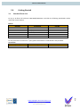
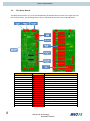
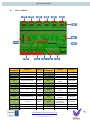
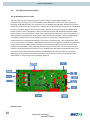
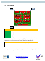
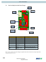
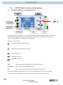
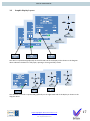
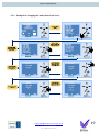
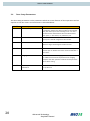
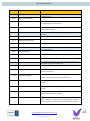
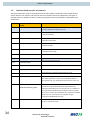
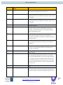
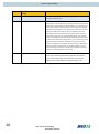
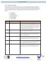
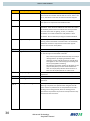
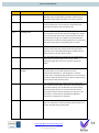
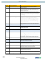
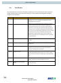
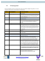
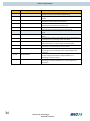
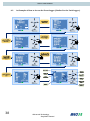
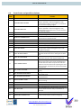
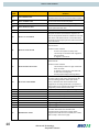
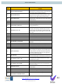
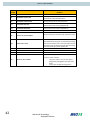
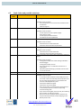
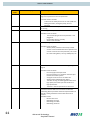
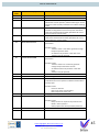
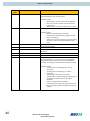
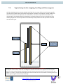
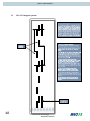
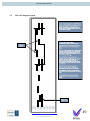
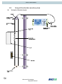
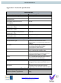
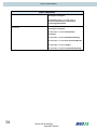

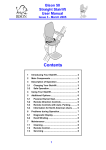


![Lifts Part 4: Operational Management [PDF 707Kb]](http://vs1.manualzilla.com/store/data/006003154_1-8f988a4c31a2e96372488ae8439271db-150x150.png)