1
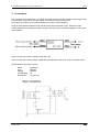
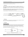
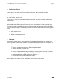
User's Manual DC-DC Converter 600-280-12
page 1
USER'S MANUAL
DC-DC CONVERTER 600-280-12
Version 1a
AES International S.a.r.l.
18 rue des Moulins
L-7784 Bissen
Luxembourg
[email protected]
www.aes-int.eu
Table of Content
1. Description .............................................................………….............................. 2
2. Connections…………..……................................................................................. 3
3 Operation ….......................................................................................................... 4
4. Mounting …………………………….................................................…...…........... 4
5. Protection ……………………………......................................................…........... 4
6. Faulty Conditions….....................................................................................….... 5
7. Warranty……………………………………………………………………………..…..5
8. Caution..………………………………………………………………………………….6
Modifications of this manual are subjected to changes without giving notice.
21-02-2010
AES
User's Manual DC-DC Converter 600-280-12
page 2
To take advantage of its features and to avoid danger for man and material, please read the
operating instructions below carefully, before operating the unit. We recommend to keep the
user’s manual for later reference.
1. Description
The DC-DC converter 600-280-12 supplies the 12V Circuitry of the electric vehicle with power from the
traction battery. It has the same function as an alternator in conventional vehicles.
The output of the converter is self protecting, through Over Voltage- (OVP; Converter shut down &
manual reset), Over Current- (OCP) and Over Thermal Protection (OTP).
It has a galvanic insulation between the high voltage and low voltage circuit. The device is based on a
the principle of a buck converter, that operates interleaved, in order to reduce ripple currents and
allows adjustment of the required voltage level in the corresponding operation mode.
It has both an input- and output filter, which gives good EMC behaviour.
The specifications are:
Input Voltage up to a maximum of 400VDC
Input Current 2,41A
Nominal Output Voltage 12VDC
Adjustable Output Voltage range 7,2 - 14,4VDC
Default Output voltage setting 13.8VDC
Maximum Output Current Current 50A
Output Voltage accuracy +/-1%
Maximum Ripple & Noise 120mV
Maximum Line & Load Regulation 48mV
Efficiency >90%,
Maximum Output Power 600W
Equipped with Heat sink
Packed in Aluminium Enclosure IP54
Typical Operating & Storage temperature -40 up to +50 degrees Celsius
Over Thermal Protection 100 Degrees Celsius (Base plate temp.)
Over Current Protection 105-140%
Over Voltage Protection 125-145
Polarity Protection by internal Input Diode
Operating & Storage Humidity 5-95%RH
Cooling; Conduction Cooled
Temperature coefficient 0,02% per degree Celsius
Isolation resistance; output to base plate 500VDC > 100MegaOhms (25 degrees C.,70%RH)
Shock 196 m/s2 (Switched Power Supply Package)
Switched Power Supply Package Safety Appr. UL60950-1,CSA60950-1,EN60950-1,CE LVD
Both Parallel & Series operation possible (Max. 11 units of the same model can be connected)
Warranty 2 Years
This power module is designed to have a withstand voltage of 2.5kVAC between input and base plate, and 3kVAC between
input and output for 1 minute. When conducting withstand voltage test during incoming inspection, be sure to set the current
limit value of the withstand voltage testing equipment to 20mA. This power module is designed to have a withstand value of
500VDC between output and base plate for 1 minute.
21-02-2010
AES
User's Manual DC-DC Converter 600-280-12
page 3
2. Connections
The converter has 4 cable wires (i.e. two input and two output). The output cables have a bigger cross
sectional area, compared to the input cables, as the latter conduct more current.
Input wiring and output wiring must be separated to improve noise sensibility.
Keep the cable distance between load and device as short as possible (<3m), otherwise output
voltage may become unstable and EMC may get worse due to an increased impedance of wiring and
load condition.
Output current of the device should be less than 40A.
The Converter has an internal high voltage fast blow type input Fuse of 6A. (refer to scheme above)
Specifications of this input Fuse are:
Brand
Type
Voltage
Current rating
Dimensions
: Bussmann
: BBS 6A
: 600VAC
: 6A
: 10.3*35 mm
.
21-02-2010
AES
User's Manual DC-DC Converter 600-280-12
page 4
The Base plate of the internal switched power supply is connected (earthed) to the aluminium
enclosure and should be connected to the vehicle chassis.
3. Operation
As like an alternator, the converter acts as a charging device, for charging the 12V battery. The
Charge Voltage is set to 13.8VDC by default. Depending on the application, this value can be set from
7,2 to 14,4VDC by turning the trim potentiometer on the PCB inside of the converter. For adjustment,
remove the lid.
The converter is designed for operation in conjunction with an on board 12V Auxiliary battery. Hence,
the battery will act as a buffer in order to stabilise the 12V Circuitry from short current peaks (e.g.
caused by switching of headlamps and/or other 12V equipment).
For improved protection, it is recommended to connect an output Fuse of 50A as per schematic below.
4. Mounting
There is no restriction on mounting direction, but there should be enough consideration for airflow, so
that heat does not accumulate around the power module vicinity.
5. Protection
Reverse input connections
Please pay attention to connect the input terminals of the converter to the right polarity. Reverse input
polarity could normally cause module damage. In order to reduce the risk of damage, a protective
diode has been installed inside of the converter, to protect the converter from reversed polarity.
This protective diode has a higher voltage rating than the input voltage (i.e. >400VDC), as well as a
higher surge current rating than the internal input Fuse.
21-02-2010
AES
User's Manual DC-DC Converter 600-280-12
page 5
6. Faulty Conditions
If OCP trips (i.e. there's an Over Current Protection Condition); there will be an automatic
recovery/reset.
If OTP trips (i.e. there's an Over Thermal Protection Condition); remove the input & cool the unit down
for a few minutes. Then re-input.
If OVP trips (i.e. there's an Over Voltage Protection Condition); remove the input for a few seconds.
Then re-input.
Normal or abnormal operation of the power module can be monitored by the IOG terminal.
IOG terminal tripping is shown by means of a red LED (i.e. a Light Emitting Diode), mounted in the
enclosure.
This signal is LOW (i.e. red LED is of) when inverter has normal operation and HIGH (i.e. red LED is
on), when the device stops or is operating abnormal. The current of the low current red LED is approx.
2mA.
Also note that IOG trips when:
• OCP condition occurs
• Light load conditions at parallel operation occur
• Dynamic Load operation occur
7. Warranty
This product carries a warranty, covering defects in materials and workmanship, for a period of 24
months (based on an 8 hours/day operation). During this warranty period, AES will, as it's option, will
either repair or replace products proved to be defective.
Warranty applies - but not limited - to the following:
• average operating temperature is under +40 Degrees Celsius
• average load factor is 80% or less
Following cases are not covered by warranty:
• improper usage and mishandling, like dropping or applying shock to the unit and defects
from operation exceeding specification of the product
• defects resulting from natural disaster (fire, flood, etc.….)
• unauthorised or incompetent modification or repair
Specifications of this product may be subjected to changes without giving notice.
21-02-2010
AES
User's Manual DC-DC Converter 600-280-12
page 6
8. Caution
"Caution High Voltage inside"
•
•
•
•
•
•
•
•
•
•
•
•
•
Have the unit installed and made operational by a skilled professional.
This converter must be earthed.
Do not make unauthorised modifications to the unit, otherwise you may have an electric shock and
void warranty.
Please note that careless handling of high DC voltages can be very dangerous and lethal.
After the DC-DC Converter is installed in the vehicle, some terminals inside of the converter
conduct high voltages. Touching these terminals could cause a severe electric shock, which
may lead to injuries or even death. For adjusting the output voltage, by turning the trim
potentiometer, we recommend to wear non conducting (rubber) gloves and the use of a non
conducting or insulated screw driver.
Do not connect the high voltage connections, before being sure that there is no high voltage on
the connections itself.
Never disconnect the high voltage connections, before being sure that there is no high voltage on
the DC-link anymore.
Use an insulation failure detector, in order to check the galvanic insulation between the high and
the low voltage DC-link.
Never operate the unit under over current or shorted conditions, for more than 30 seconds,
otherwise this may lead to damage.
This unit produces waste heat. Touching the hot unit can cause injuries and burnings. Please do
not install easy flammable materials close to the unit.
Avoid operation of the device next to a heat source or in direct sunlight.
Take note that moisture could lead to power module abnormal operation or damage.
Ensure sufficient ambient cooling of the device. Proper cooling has a positive effect on the life
time.
Not withstanding the proper IP protection (IP54), we recommend not to expose the unit to rain or
splash water.
21-02-2010
AES