1
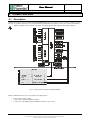
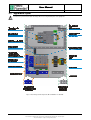
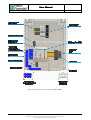
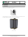
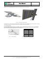
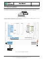
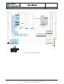
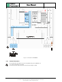
User Manual
Pagina 1 di 26
FIO RTU
FIO SOLAR
Remote Terminal Unit per FIO 2.0
User manual
Edtion
0
Revision
1
Date
09/10/2014
User Manual
Electronic and Integrated Systems Division – San Pietro Mosezzo (NO) - Italy
Page 2 di 26
Index
1.
Information ...................................................................................................................................................... 4
1.1
Index of revisions
4
1.2
Symbols
4
1.2.1
Symbols in this manual
4
1.2.2
Symbols on the appliance
4
1.3
Contacts
4
1.4
Product identification
5
1.5
Marking and identification
5
1.5.1
1.6
2.
3.
Safety requirements
8
Electric safety
8
1.6.2
Installation Precautions
8
1.6.3
Fuses
8
1.6.4
Cables
8
1.6.5
Batteries
8
1.6.6
Internal temperatures
8
1.6.7
ESD precautions
8
Product overview............................................................................................................................................ 9
2.1
Description
2.2
Apparatus layout
9
10
Installation ..................................................................................................................................................... 13
3.1.1
3.2
Mechanical
13
Solar panel installation
14
Electrical installation
15
3.2.1
Terminal blocks
15
3.2.2
General information
17
3.2.3
Cable glands
18
3.2.4
Power supply
18
3.2.5
Data connections
18
3.3
Cables
19
3.3.1
Ex conformity
20
3.3.2
Maximum cable length
20
3.4
5.
7
1.6.1
3.1
4.
Ex parameters table
Settings
21
3.4.1
Serial communication isolator settings
21
3.4.2
Remote power supply settings
21
3.4.3
Digital signal isolator settings
21
3.4.4
24V Power supply settings
21
Operation ....................................................................................................................................................... 22
4.1
Description
22
4.2
Led signaling
22
4.2.1
RS485/RS232 repeater/isolator
22
4.2.2
Switching repeater/isolator
22
4.2.3
Remote PWS
22
4.2.4
Battery charger
22
4.2.5
PWS- DC/DC converter 24V
23
Technical data............................................................................................................................................... 24
FIO RTU / SOLAR – User manual – Ed. 0 Rev. 1
The information contained in this document are confidential and owned by Pietro Fiorentini S.p.A.
The technical data are subject to change without notice.
User Manual
Electronic and Integrated Systems Division – San Pietro Mosezzo (NO) - Italy
6.
Page 3 di 26
5.1
General
24
5.2
Power supply
24
5.3
Functional
25
5.4
Normative compliance
25
Manteinance .................................................................................................................................................. 26
6.1
Battery
26
6.1.1
Battery life
26
6.1.2
Battery replacement
26
6.1.3
Fuse
26
FIO RTU / SOLAR – User manual – Ed. 0 Rev. 1
The information contained in this document are confidential and owned by Pietro Fiorentini S.p.A.
The technical data are subject to change without notice.
User Manual
Electronic and Integrated Systems Division – San Pietro Mosezzo (NO) - Italy
Page 4 di 26
1. Information
1.1
Index of revisions
Revision
0.1
Date
Reason of change
09/10/2014 First release
1.2
Symbols
1.2.1
Symbols in this manual
Pay attention to instructions
Use precautions against electrostatic discharge
1.2.2
Symbols on the appliance
Pay attention to the indications regarding the Max limits admitted for the power supply and the input and output
signals. Pay attention to the temperature of the terminals of the relay outputs and their connection cables.
Earth connection point.
1.3
Contacts
The product is manufactured by
Electronic and Integrated Systems Division
Contacts for sales and support
Via Pasteur 1/3 – 28060 San Pietro di Mosezzo (NO) Italy
Tel.: 0321/538111 – Fax: 0321/538150
www.fiorentini.com
FIO RTU / SOLAR – User manual – Ed. 0 Rev. 1
The information contained in this document are confidential and owned by Pietro Fiorentini S.p.A.
The technical data are subject to change without notice.
User Manual
Electronic and Integrated Systems Division – San Pietro Mosezzo (NO) - Italy
1.4
Page 5 di 26
Product identification
The products have the name FIO RTU and FIO SOLAR and several models are available according to the power and functionality
installed.
Code
Description
AP0670T02M01R00
FIO2 RTU cabinet 115-230VAC +LF/HF+RS232/485
AP0670T02M02R00
FIO2 RTU cabinet 24V DC +LF/HF+RS232/485
AP0670T02M03R00
FIO2 Power Box 115-230VAC
AP0670T02M04R00
FIO2 RTU cabinet 115-230VAC +RS232/485
AP0670T02M05R00
FIO2 RTU cabinet 115-230VAC +LF/HF
AP0670T02M06R00
FIO2 RTU cabinet 24VDC +RS232/485
AP0670T02M07R00
FIO2 RTU cabinet 24VDC +LF/HF
AP0670T03M01R00
FIO2 Solar Power box (20W-12Ah)
AP0670T03M02R00
FIO2 Solar RTU cabinet (20W-12Ah) +LF/HF
AP0670T03M03R00
FIO2 Solar RTU cabinet (20W-12Ah) +RS232/485
AP0670T03M04R00
FIO2 Solar RTU cabinet (20W-12Ah) +LF/HF+RS232/485
NOTE
Power Box
Cabinet
LF/HF
RS232/485
20W – 12Ah
the device has only the remote power section
apparatus that also integrates the signal interfacing devices
apparatus that integrates an isolator for digital signal repeater
apparatus that integrates an insulator for the conversion from RS232 to RS485
20W solar panel and 12Ah lead-acid battery
The "code" is not listed on the device’s label
1.5
Marking and identification
On the front there is a label that contains the information to identify the individual apparatus, certifications and the main parameters.
•
•
•
•
•
Logo and address of the manufacturer
Model Name
Serial number
CI
Certifications
Apparatus name
numeric code that uniquely identifies the single apparatus
product configuration
Model Name
FIO RTU 115-230VAC
FIO RTU 24VDC
FIO SOLAR
Serial Number
YYASnnnn
YY
AS
nnnn
two digits to indicate the year of manufacture
apparatus type
progressive number
CI
Digital Output
1
Digital output isolator installed
0
Digital output isolator not installed
Serial Interface
S2
RS485 to RS232 isolator converter installed
0
Serial interface not installed
Example
S/N
13AS0010
CI
DOS2
Year of manufacture 2013, apparatus type AS, progressive number: 0010
Digital output isolator: installed
Serial interface isolator: Installed
FIO RTU / SOLAR – User manual – Ed. 0 Rev. 1
The information contained in this document are confidential and owned by Pietro Fiorentini S.p.A.
The technical data are subject to change without notice.
User Manual
Electronic and Integrated Systems Division – San Pietro Mosezzo (NO) - Italy
Fig. 1 - Apparatus identification label for FIO RTU 115-230V
Fig. 2 - Apparatus identification label for FIO RTU 24VDC
Fig. 3 - Apparatus identification label for FIO SOLAR
FIO RTU / SOLAR – User manual – Ed. 0 Rev. 1
The information contained in this document are confidential and owned by Pietro Fiorentini S.p.A.
The technical data are subject to change without notice.
Page 6 di 26
User Manual
Electronic and Integrated Systems Division – San Pietro Mosezzo (NO) - Italy
1.5.1
Page 7 di 26
Ex parameters table
The table is the same for both products
PWS
DOUT
SERIAL
Uo (V)
15.6
9.6
5.88
Io (mA)
160
10
50
Po (mW)
2496
24
73.3
Co (uF)
3.03
26
1000
Lo (mH)
0.35
1000
56
Ui (V)
5.88
Ii (mA)
-
Pi (mW)
-
Description of the symbols and label data
Sira 13ATEX2344 / 45
IECEx Sira 13.0133/ 34
Number of the certificate of conformity to ATEX standards
Number of the certificate of conformity to IECEx standards
0722
CE Logo
ID of the notified body (IMQ)
II
(2) G
[Ex ib]
IIB
Tamb: -20°C / +60°C
Ex Logo
Apparatus group (II surface)
Output IS category (2), Atmosphere type (G)
Type of protection – Associated apparatus
Gas group
temperature field in which is guaranteed compliance with IS
FIO RTU / SOLAR – User manual – Ed. 0 Rev. 1
The information contained in this document are confidential and owned by Pietro Fiorentini S.p.A.
The technical data are subject to change without notice.
Ci (uF)
0
0.003
0
Li (mH)
0
0
0
User Manual
Electronic and Integrated Systems Division – San Pietro Mosezzo (NO) - Italy
1.6
Safety requirements
1.6.1
Electric safety
Page 8 di 26
This apparatus can be powered at mains voltage 115-230VAC or 24VDC low-voltage. The installation and connection to the mains must
be carried out by authorized installers.
A main switch or circuit breaker must be installed upstream of the device. Place the switch near the device and within the area of
installation in an easily accessible position.
The earth connection is compulsory. Use a yellow/green cable of minimum section of 2.5 mm2, crimp on this a ring terminal with 4-5
mm internal diameter. Firmly attach the ground screw terminal of the device identified by the symbol
at the bottom of the container.
The ground wire must be connected to the earth of the installation site. Execute the ground connection before connecting the power
supply.
Security Panel for power supply terminals
The Security Panel of the Terminal (RTU 115-230V) is an integral part of protection devices do not remove the security panel
with mains voltage present.
1.6.2
Installation Precautions
To prevent bits of wire or other material from reaching the interior of the apparatus, perform the termination and cable wiring before
installing the apparatus.
Ventilation grids of the internal devices
Do not obstruct the grids of internal devices. Pay attention that no metallic fragment enters grids. If liquid enters into the
openings, immediately disconnect the power supply, do not use the appliance and contact the manufacturer's technical
support.
Installation area
FIO RTU / SOLAR are associated apparatus
Install them in SAFE AREA
1.6.3
Fuses
Only for FIO SOLAR
The apparatus contains one user-replaceable fuse only. In case of replacement, for the continuity of safety, replace with the same type
as indicated in the technical specifications.
1.6.4
Cables
This apparatus is certified ATEX/IECEX for installation in safe area. Use only the cables type indicated in the technical specification.
1.6.5
Batteries
Only for FIO SOLAR
This device contains a lead-acid battery. The battery is installed on the bottom and blocked by a special support. The battery is
replaceable by the user only with an identical model.
1.6.6
Internal temperatures
Internal devices heat up during operation but no dangerous temperatures for the user are reached.
1.6.7
ESD precautions
The internal circuit boards of the devices used within the FIO RTU/SOLAR (barriers/Insulators) can be damaged by electrostatic
discharge that may be produced by the operator. The boards are not accessible; you should take precautions when accessing terminals
for wiring.
-switch off the apparatus
-discharge your electrostatic charge by touching a metal surface that is connected to the ground
- If available use a wrist strap (connected to ground)
WARNING
Failure to comply with the requirements described in this manual or use in an unspecified way, may affect the protections
provided.
FIO RTU / SOLAR – User manual – Ed. 0 Rev. 1
The information contained in this document are confidential and owned by Pietro Fiorentini S.p.A.
The technical data are subject to change without notice.
User Manual
Electronic and Integrated Systems Division – San Pietro Mosezzo (NO) - Italy
Page 9 di 26
2. Product overview
2.1
Description
FIO RTU (Five In One – Remote Terminal Unit) and FIO SOLAR (RTU solar power supply) are a series of devices suitable to connect
Ex-i devices installed in hazardous area. In particular, FIO RTU and SOLAR are designed to connect to the controller named FIO 2.0.
FIO RTU e SOLAR must be installed in safe area as associated apparatus with compliance with directives 94/9 EC.
Fig. 4 - System architecture FIO 2.0 – FIO RTU/SOLAR
FIO RTU / SOLAR with reference to the model do the following functions:
•
•
•
Remote power supply for FIO2
Isolator serial converter from RS485 to RS232
Isolator for the output digital signal from FIO2.0 from Namur to open collector
FIO RTU / SOLAR – User manual – Ed. 0 Rev. 1
The information contained in this document are confidential and owned by Pietro Fiorentini S.p.A.
The technical data are subject to change without notice.
User Manual
Electronic and Integrated Systems Division – San Pietro Mosezzo (NO) - Italy
2.2
Apparatus layout
Use measures to prevent electrostatic discharges when accessing internal parts of the equipment
Fig. 5 – Internal layout and components ID for FIO RTU 115-230VAC
FIO RTU / SOLAR – User manual – Ed. 0 Rev. 1
The information contained in this document are confidential and owned by Pietro Fiorentini S.p.A.
The technical data are subject to change without notice.
Page 10 di 26
User Manual
Electronic and Integrated Systems Division – San Pietro Mosezzo (NO) - Italy
Fig. 6 – Internal layout and components ID for FIO RTU 24VDC
FIO RTU / SOLAR – User manual – Ed. 0 Rev. 1
The information contained in this document are confidential and owned by Pietro Fiorentini S.p.A.
The technical data are subject to change without notice.
Page 11 di 26
User Manual
Electronic and Integrated Systems Division – San Pietro Mosezzo (NO) - Italy
Fig. 7 – Internal layout and components ID for FIO SOLAR
FIO RTU / SOLAR – User manual – Ed. 0 Rev. 1
The information contained in this document are confidential and owned by Pietro Fiorentini S.p.A.
The technical data are subject to change without notice.
Page 12 di 26
User Manual
Electronic and Integrated Systems Division – San Pietro Mosezzo (NO) - Italy
Page 13 di 26
3. Installation
3.1
Mechanical
FIO RTU e SOLAR cabinets can be installed on the wall or pole.
Wall mounting is accomplished by the supplied accessories (Legrand, 036409 code) which can be mounted on the back of the cabinet.
Use grub screw anchors or screws depending on the installation wall.
Fig. 8 – Wall mounting support
The drawings with drilling dimensions are available on a separate document of the manufacturer of the cabinet attached to the product.
Pole mounting is accomplished via custom adapters to be fastened to the back of the cabinet by bolts
Fig. 9 – Pole mounting
FIO RTU / SOLAR – User manual – Ed. 0 Rev. 1
The information contained in this document are confidential and owned by Pietro Fiorentini S.p.A.
The technical data are subject to change without notice.
User Manual
Electronic and Integrated Systems Division – San Pietro Mosezzo (NO) - Italy
3.1.1
Page 14 di 26
Solar panel installation
20W Solar Panel is supplied with brackets for fixing to the pole with the structure shown in Fig. 7.
Fig. 10 – Solar panel mounting structure
The Panel must be secured using the screws included and orienting the longest side horizontally. Refer also to the instructions included
in the Panel. The jaws on the rear side of the structure are used to fasten the structure to the pole.
3.1.1.1 Panel orientation
The Panel should be oriented in such a way as to maximize exposure to sunlight within a year. Orient the Panel to South if installed in
the northern hemisphere and to North when installed in the southern hemisphere. Tilt relative to the horizon of the angle indicated in
table 1. Check that throughout the day the Panel is not in shadow areas.
Tilt angle
Fig. 11 – Panel orientation
Latitude (L)
Angle α
0° - 15°
15° - 25°
25° - 30°
15°
L
L+5°
30°- 35°
35° - 40°
≥ 40°
L+10°
L+ 15°C
L+20°
Tab. 1 – Tilt angle
FIO RTU / SOLAR – User manual – Ed. 0 Rev. 1
The information contained in this document are confidential and owned by Pietro Fiorentini S.p.A.
The technical data are subject to change without notice.
User Manual
Electronic and Integrated Systems Division – San Pietro Mosezzo (NO) - Italy
3.2
Electrical installation
3.2.1
Terminal blocks
Page 15 di 26
The terminal blocks are divided into two groups with colors Blue and gray, the cable glands are grey and blue also. The signal terminal
blocks and the solar panel terminal blocks consist of two levels. The Jn in red identifies the terminal block ( see dwg below )
J ( first digit )
J ( second digit )
Fig. 12 – Two levels terminal block
The blue group identifies the intrinsically safe connections (IS) and is reserved for the connection to the FIO 2.0 gray group is to connect
power and to connect the equipment to those in safe area (PLC, PC.)
Fig. 13 – Connections for FIO RTU 115-230VAC
FIO RTU / SOLAR – User manual – Ed. 0 Rev. 1
The information contained in this document are confidential and owned by Pietro Fiorentini S.p.A.
The technical data are subject to change without notice.
User Manual
Electronic and Integrated Systems Division – San Pietro Mosezzo (NO) - Italy
Fig. 14 – Connections for FIO RTU 24VDC
FIO RTU / SOLAR – User manual – Ed. 0 Rev. 1
The information contained in this document are confidential and owned by Pietro Fiorentini S.p.A.
The technical data are subject to change without notice.
Page 16 di 26
User Manual
Electronic and Integrated Systems Division – San Pietro Mosezzo (NO) - Italy
Fig. 15 – Connections for FIO SOLAR
3.2.2
General information
Keep separated the cable paths for the IS circuits (BLUE cable) from the NON-IS ones
Use a single cable gland for each cable
The cables must pass and be fixed in the respective blue and grey conduits
FIO RTU / SOLAR – User manual – Ed. 0 Rev. 1
The information contained in this document are confidential and owned by Pietro Fiorentini S.p.A.
The technical data are subject to change without notice.
Page 17 di 26
User Manual
Electronic and Integrated Systems Division – San Pietro Mosezzo (NO) - Italy
3.2.3
Page 18 di 26
Cable glands
Grey cable glands
PWS connection
Data connection to external apparatus
Ground peg: ground connection
BLU cable glands
Connections to FIO2.0
Gray cap: pressure equalizer
Fig. 16 – Cable glands
3.2.4
Power supply
Connect the earth cable to the appropriate peg on the bottom
Use unipolar cable Y/G 2.5 mm2
3.2.4.1 RTU 115-230V
Make sure you have removed the power supply connection. Turn OFF the circuit breaker inside the FIO RTU. Connect the cables
according to the Neutral- Line indications
On this version there is a transparent Security Panel for the power terminals (not visible in drawings) restore the Panel
immediately after making the connections
3.2.4.2 RTU 24VDC
Make sure you have removed the power supply connection. Turn OFF the circuit breaker inside the FIO RTU. Connect the cables
according to the “+” and “–“indications
3.2.4.3 RTU SOLAR
Turn OFF the circuit breaker inside the FIO RTU.
Lift the battery fuse holder cap.
Insert the battery positive fast on type terminal
Connect the cable coming from the Solar Panel respecting the polarity
3.2.5
Data connections
Connections to FIO2.0
Use the shielded cable specified in the chapter “cables “
Connect to FIO2.0 using the following table and image
FIO2
Signal
(EXT. PW SUPPLY)
Digital signal
(DOUT-N)
RS485
(RSA)
FIO RTU / SOLAR
Terminal
M19.1
Positive
M19.2
Negative
M19.3
Shield
M12.1
Positive
M12.2
Negative
M12.3
Shield
M13.1
A+
M13.2
BM13.3
Shield
RTU 115-230VAC
J1
J2
N.C.
J5
J6
N.C.
J3
J4
N.C.
RTU 24VDC
J5
J6
N.C.
J9
J10
N.C.
J7
J8
N.C.
SOLAR
J1
J2
N.C.
J5
J6
N.C.
J3
J4
N.C.
FIO RTU / SOLAR – User manual – Ed. 0 Rev. 1
The information contained in this document are confidential and owned by Pietro Fiorentini S.p.A.
The technical data are subject to change without notice.
User Manual
Electronic and Integrated Systems Division – San Pietro Mosezzo (NO) - Italy
Page 19 di 26
Fig. 17 – FIO2.0 – connections to FIO RTU apparatus
Connections to apparatus in safe area
Use a shielded cable for data connection
External apparatus
Type
RS232 output
Digital output
Signal
TXD
RXD
GND
+
-
FIO RTU / SOLAR
RTU 115-230VAC
J9
J8
J7
J10
J11
RTU 24VDC
J13
J12
J11
J14
J15
SOLAR
J9
J8
J7
J10
J11
Connect the shield on FIO2 side in the specified terminal
Shield on FIO RTU / SOLAR side NOT CONNECTED
3.3
Cables
The cables that connect 2.0 with FIO FIO RTU/SOLAR must meet some requirements for the installation in hazardous area.
Type
Shielded
Insulation
≥ 600Vrms
Insulation thickness
≥ 0.25mm
Maximum temperature
> +70°C
Inductance / Capacity
see § 3.3.2
The following cables are recommended
Data connections (RS485 and digital)
Manufacturer
Kabeltronik
Model
020202500
Conductors
2x0.25mm2
Capacity
120pf /m
Alternative
Manufacturer
Model
Conductors
Inductance
Capacity
AlfaWire
3231
2 x 0.33mm2
66nH/ m
27pf /m
FIO RTU / SOLAR – User manual – Ed. 0 Rev. 1
The information contained in this document are confidential and owned by Pietro Fiorentini S.p.A.
The technical data are subject to change without notice.
User Manual
Electronic and Integrated Systems Division – San Pietro Mosezzo (NO) - Italy
Page 20 di 26
Remote power supply connection
Manufacturer
AlfaWire
Model
3231
Conductors
2 x 0.52mm2
Inductance
55nH/ m
Capacity
30pf /m
3.3.1
Ex conformity
All devices connected to the FIO 2.0 must be placed IN SAFE AREA and must be approved as Associated Devices, and must be
compatible to the SECURITY PARAMETERS (IS). FIO RTU and SOLAR are compatible, however the evaluation should be taken into
account also the connecting cable. In particular, it must be
Associated device parameter
Uo
Io
Po
Co
Lo
CONDITION
≤
≤
≤
≥
≥
FIO2.0 parameter
Ui
Ii
Pi
Ci + cable capacity
Li + cable indictance
The condition must be respected even in the opposite direction where applicable
Uo / Io / Po
Ui / Ii / Pi
Ci / Li
Co / Lo
C cable, L cable
maximum voltage / Current / Output power output from the associated device (RTU / SOLAR)
maximum voltage / Current / FIO2.0 Input power
maximum Capacity / inductance present at the input terminals of the FIO 2.0
maximum Capacity/ Applicable inductance to the associated device terminals (RTU/SOLAR)
maximum Capacity/ Cable inductance ( considering the length also )
Pietro Fiorentini S.p.A declines any liability from risks and consequences arising from non-observance of these instructions.
3.3.2
Maximum cable length
Taking into account the Ex restrictions, functional lengths allowed are
•
•
•
RS485
Digital IN
Remote power supply
Functional
RS232
Digital
1200m (max 56.7Kb/s)
100m
100m
15m
100m
The ground wire, and only that, should be yellow/green
FIO RTU / SOLAR – User manual – Ed. 0 Rev. 1
The information contained in this document are confidential and owned by Pietro Fiorentini S.p.A.
The technical data are subject to change without notice.
User Manual
Electronic and Integrated Systems Division – San Pietro Mosezzo (NO) - Italy
3.4
Page 21 di 26
Settings
Internal devices have some sliders and potentiometers. The apparatus comes with these presets.
3.4.1
Serial communication isolator settings
Model
Default settings
STAHL 9185
19200, 8, N, 1
Slider
BAUD
RS2.1 (SCAN)
RS2.2
RS3.1
RS3.2
Position Min
5
OFF
OFF
OFF
ON
3.4.2
Max
1 (1200baud)
8 (57.6 Kbaud)
Remote power supply settings
Model
Default setting
STAHL 9143
12V
Do not change the preset value. Any adjustments must return the power to the preset value. The Indications are for reference
only
Potentiometer
Trimmer UA
3.4.3
Position
set to minimum
Digital signal isolator settings
Model
Default setting
STAHL 9170
LF1: OFF, INV1: OFF
Slider
DIP 1
DIP 2
DIP 3
DIP 4
LF1
INV1
not active
not active
Position ON
Line fault detection enabled
Inverts the output signal (NC)
3.4.4
24V Power supply settings
Position OFF
Line fault detection disabled
Do not Invert the output signal (NO)
The power supplies in the RTU model 115-230VAC and Solar have a trimmer for adjusting the output voltage. Do not change the default
24V-0/1V.
FIO RTU / SOLAR – User manual – Ed. 0 Rev. 1
The information contained in this document are confidential and owned by Pietro Fiorentini S.p.A.
The technical data are subject to change without notice.
User Manual
Electronic and Integrated Systems Division – San Pietro Mosezzo (NO) - Italy
Page 22 di 26
4. Operation
4.1
Description
FIO RTU devices and SOLAR are the interface between the FIO 2.0 installed in hazardous area and the devices installed in the safe
area.
Switch
All models are equipped with a circuit breaker. Move up the lever to switch on the apparatus.
Remote power supply
Provides power to the FIO 2.0 used only to recharge the lithium-ion rechargeable battery inside.
Signal repeating
Conversion interface and galvanic isolation between the RS485 serial A (or B) of FIO 2.0 and an external device with RS232 interface.
Uses the TX and RX signals only.
Namur contact repeater
Conversion interface and galvanic isolator between the output Namur standard of the FIO2 and an external device. The interface is
open drain type. If using inductive devices you must put a diode as indicated in figure below
4.2
Led signaling
Internal devices have some LEDs. See the layout to identify the device
4.2.1
RS485/RS232 repeater/isolator
LED
PWR
ERR
Color
Green
Red
RxD1
RxD2
RxD3
Green
Green
Green
4.2.2
Switching repeater/isolator
LED
PWR
LF
OUT1
4.2.3
Color
Green
Red
Yellow
Color
Green
Function
ON: Power present
Battery charger
Only for FIO Solar
LED
INFO
BATT
Function
ON: Power present
Line Fault: short circuit or non-compliant level of Namur signal
Output status= ON: active
Remote PWS
LED
PWR
4.2.4
Function
ON: Power present
ON: short circuit RS232 or RS485 lines
Flashing: baud rate auto tuning (not used)
Rx signal monitor RS 232 signal (from PC / PLC)
Not used
Rx signal monitor RS 485 signal (from FIO2.0)
Color
Two-colors
(Green/Red)
Three-colors
Red,Yellow,
Green
Function
Green: normal operation
Red, flashing: overload, over temperature
Red: low battery voltage
Red+Green: battery voltage too high
Red flashing slowly: low voltage battery, load disconnected
Red flashing quickly: low battery voltage, battery charging
Yellow-green: battery level
Green flashing quickly: battery full, stand-by function
FIO RTU / SOLAR – User manual – Ed. 0 Rev. 1
The information contained in this document are confidential and owned by Pietro Fiorentini S.p.A.
The technical data are subject to change without notice.
User Manual
Electronic and Integrated Systems Division – San Pietro Mosezzo (NO) - Italy
4.2.5
PWS- DC/DC converter 24V
RTU 24VDC excluded
LED
PWR
Color
Green
Function
ON: Power present
FIO RTU / SOLAR – User manual – Ed. 0 Rev. 1
The information contained in this document are confidential and owned by Pietro Fiorentini S.p.A.
The technical data are subject to change without notice.
Page 23 di 26
User Manual
Electronic and Integrated Systems Division – San Pietro Mosezzo (NO) - Italy
Page 24 di 26
5. Technical data
5.1
General
Parameter
Technical data
Cabinet type
Cabinet with opening door
Material
Polyester reinforced with glass fiber
Dimensions
400x300x200mm (cable glands excluded)
Weight
RTU
SOLAR
Degree of protection
IP65
Operating temperature
-20°C / +60°C
Storage temperature
-30°C / +70°C
Relative humidity
≤ 50% a +40°C non condensing
Max operating altitude
≤ 2000m
Connection
DIN mounted terminal blocks max 6mm2 / ground connection = threaded M4
Cable glands
PG11
5.2
7.5Kg
11Kg
Power supply
Parameter
Technical data
RTU
Model RTU 115-230VAC
100–240VAC, 50-60Hz, 3.15A
Model RTU 24VDC
20V–30V, 0.6A
Protections
Magneto-Thermal Switch/Surge Protector
Service socket
(only for RTU 115-230VAC)
Schuko 2.5A max
In/Out isolation
3KVAC
SOLAR
Solar panel rating
Max 40W, open circuit voltage 45V max, battery charging current 3A max
Standard panel
Kyocera KC21 (21W) or equivalent
Battery
YUASA NP12-12 (12V / 12Ah)
Autonomy
All the functions
Remote PWS+ Digital isolator
Remote PWS+ Serial isolator
100%Recharging time
≤ 10 h (Standard panel, insolation 100%)
Protections
Magneto-Thermal Switch/ Battery fuse (5x20mm 10A - 1500A)
Insulation (DC/DC converter)
1.5KVAC
≥ 18 h
≥ 24 h
≥ 20 h
FIO RTU / SOLAR – User manual – Ed. 0 Rev. 1
The information contained in this document are confidential and owned by Pietro Fiorentini S.p.A.
The technical data are subject to change without notice.
User Manual
Electronic and Integrated Systems Division – San Pietro Mosezzo (NO) - Italy
5.3
Page 25 di 26
Functional
Function
Parameter
Technical data
Bandwidth
0Hz - 10KHz
Input
Standard Namur (polarization 8.2V)
Output
Open Drain 30VDC, 5mA max
Insulation
300VAC
Standard Input
RS485 , 2 wires
Standard output
RS232 , 2 wires
Max baud rate
38.4Kbaud
Insulation in/out
1.5KVAC
Voltage
12V
Current
160mA
Insulation in/out
1.5KVAC
Switching Repeater
Fieldbus Isolating Repeater
FIO output PWS
(Ex i Power Supply)
5.4
Normative compliance
Type
Electrical safety
EMC
Intrinsic safety
Norma
Description
EN-60950-1
IEC-60950-1
Information technology equipment - Safety - Part 1: General requirements
EN 61326-1 Electrical equipment for measurement, control and laboratory use EMC
requirements - Part 1: General requirements
EN 61000-6-3 (General requirements - Emission for residential environments,
commercial light industrial)
EN 61000-6-2 (Generic standards-immunity for industrial environments)
EN 60079-0: 2012
EN 60079-11: 2012
IEC 60079-0: 2011
IEC 60079-11: 2011
FIO RTU / SOLAR – User manual – Ed. 0 Rev. 1
The information contained in this document are confidential and owned by Pietro Fiorentini S.p.A.
The technical data are subject to change without notice.
User Manual
Electronic and Integrated Systems Division – San Pietro Mosezzo (NO) - Italy
Page 26 di 26
6. Manteinance
No maintenance operations are envisioned except for battery replacement
6.1
Battery
6.1.1
Battery life
Replace the battery with annual periodicity.
If the place of installation has an average high temperature, replace the battery every 6 months.
6.1.2
Battery replacement
Follow this procedure
•
•
•
•
•
•
•
Switch off the apparatus
Open the fuse holder and remove the fuse
Disconnect the cables from the battery
Remove the fixing screws of the support frame
Remove the battery
Insert the new battery and fix it
Reconnect the cables
Dispose of spent batteries using the special containers
6.1.3
Fuse
The fuse should never intervene.
In case of intervention replaced with the same model
Type
IN
Voltage
Breaking Power
5x20mm ceramic
10A Retarded
250VAC
1500A
If after the replacement occurs a new intervention, disconnect the battery switch off the appliance and do not use it.
FIO RTU / SOLAR – User manual – Ed. 0 Rev. 1
The information contained in this document are confidential and owned by Pietro Fiorentini S.p.A.
The technical data are subject to change without notice.


![Fio 2.0 UM ECU [ENG]](http://vs1.manualzilla.com/store/data/005638068_1-6dee15c8bb797972f1fa6aeeeee54189-150x150.png)