1
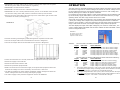
CONTENTS
Page(s)
Subject
Safety
2
Main SVS Features
3
SVS Specification
4 - 5
Unpacking
6
Inspection
6
Installation
6 - 9
Operation
Sollatek SVS Range
10 - 11
Troubleshooting
11
Guarantee
11
Warranty Returns
12
Voltage Stabilisers
User Manual
SAFETY
• FOLLOW all safety instructions and use caution when installing and operating any
electrical equipment.
• CHECK that the voltage of the mains electricity supply is the same as the voltage of
the SVS (see label on back) BEFORE connecting the SVS to the electricity supply.
• CHECK that the maximum current rating of the equipment you intend to connect does
not exceed the maximum current rating of the SVS unit (see label on back plate)
BEFORE connecting the SVS to the electricity supply.
[ Most equipment is labeled to show the maximum current rating. If connecting more
than one item of equipment calculate the total current rating by adding all of the
current ratings together.]
• DO NOT expose this equipment to rain, moisture or liquid spillage.
• DO NOT insert any object into the ventilation slots.
IMPORTANT
Keep handy for reference.
• DO NOT attempt to dismantle the SVS, as this will invalidate the guarantee. There are
no user serviceable parts inside
• The SVS was designed and is manufactured by Sollatek (UK) Ltd and complies with
the safety codes of practice.
Contains important safety information
2
MAIN SVS FEATURES
SVS SPECIFICATIONS
In many places local electricity generating companies have difficulty keeping the
voltage level of the supply to consumers within set safe* limits.
Operating Voltage
: 230VAC (optional factory setting from 200 to 240VAC)
Stabilisation Range
: From 164 to 284V (230VAC from –29% to +23%)
Any electrical equipment can easily be damaged or destroyed if voltage of the mains
electricity supply rises above or falls below these limits.
Output Voltage
If the voltage level rises above the safe range this can be specially harmful to
equipment with electronic circuits, such as TV’s, hi-fi’s, computers, faxes, copiers, etc.
: Input 171 - 275V output = 216 to 244V (230VAC +/- 6%).
: Input 164 - 171V output = 207 to 216V (230VAC +/- 10%)
: Input 274 - 285V output = 244 to 253V (230VAC +/- 10%)
Maximum load
: SEE TABLE A.
If the voltage drops below the safe range this can be especially harmful to electrical
equipment with a motor, such as refrigerators, freezers, chillers, AC systems, etc.
Frequency
: 50/60 Hz [45 to 88Hz & 30Hz for short periods only]
Speed of response
: 750V per second.
Spike protection
: MOV on high voltage input rated at 160 Joules – 320VAC.
: MOV on low voltage controls rated at 3.5 Joules – 50VDC.
A Sollatek SVS is a voltage stabiliser (aka ‘regulator’) and its main purpose is to correct
any under or over voltage condition so the electricity supply doesn’t harm equipment.
All SVS models use microprocessor controls that constantly monitor the voltage level of
the incoming electricity supply to the protected equipment. When a threatening fall or
rise in voltage level is detected the SVS automatically corrects the condition using relay
operated tap set switching stabilisation technique to produce a safe output.
Indicators
: LED displays; 7 for Input voltage, 5 for Output Voltage.
Input / Output connection
: SVS01-22EL (UK13) to SVS06-22EL (UK13);
INPUT
Plug, BS 1363 3-pin on 1metre, 3-core cable.
OUTPUT Socket, to accept BS 1363 plug.
: SVS15-22EL (UK15);
INPUT
Unterminated 1metre, 3-core cable.
OUTPUT Socket, to accept BS 546 plug.
The SVS is fast acting, reliable and economic solution to the need to protect electrical
and electronic equipment from the harm caused by voltage fluctuations.
: SVS18-22EL (TC);
INPUT Unterminated 1metre, 3-core cable.
OUTPUT Unterminated 1metre, 3-core cable.
AVS Feature
: SVS35-22EL (TC) to SVS75-22EL (TC)
The SVS has an Automatic Voltage Switcher (AVS) feature. This has two functions.
Firstly to prevent harm to equipment should the electricity supply too rapidly switch ON
and OFF. The AVS feature monitors the time between these events and automatically
delays switching on the supply to the equipment if the interval is very short.
The AVS feature is especially helpful when protecting any equipment with an electric
motor. If the electricity supply switches on and off too rapidly this can easily cause the
motor to jam and burn out and the expense of replacement or even new equipment.
Secondly the AVS feature will disconnect the supply to the protected equipment if the
voltage level go to extreme levels and beyond the SVS units’ capacity to stabilise.
Spike Protection
The SVS also includes spike protection components. These help to prevent or reduce
the harmful effects of high voltage spikes on the incoming supply.
INPUT
Terminal connections (LNE).
OUTPUT Terminal connections (LNE)
Controls
: On / Off switch.
Very Hi & Lo Voltage
- Protection (AVS
: Disconnection voltages. HIGH at 295V. LOW at 145V
: Auto reconnect after 10 sec. delay when voltage 290V to 150V
Fuse*
: Anti surge 20mm ceramic, rated 6.3A.
EMC standards
: EN 50022 – 81 – 82 and EN 61000-4-2 to 4-6 and 4-11.
Temperature range
: 0˚ to 40˚C ambient (re-rating required above 40˚C).
Relative humidity
: 95% non-condensing.
Altitude
: Up to 1,500m (re-rating required above this height).
Audible noise
: >45dB
Housing
: SVS01-22EL (UK13) to SVS18-22EL (TC) ;
ABBSlastic enclosure IP20 rated.
High voltage spikes can be caused by other nearby equipment being switched on and
off and also, most damagingly, by a lightning strike travelling along connecting cables.
The Sollatek SVS Voltage Stabiliser is designed to ensure that your electrical equipment
is protected from the harmful effects of mains voltage fluctuation, rapid mains ON and
OFF switching as well as high voltage spikes on the incoming electricity supply.
With a Sollatek SVS Voltage Stabiliser in place your electrical equipment keeps working.
* As set by the local country electricity supply authority.
3
: SVS35-22EL (TC) to SVS75-22EL (TC) ;
Metal case, black powder coated, IP21
Dimensions
: SEE TABLE B.
* Output circuit breakers (single pole) are fitted as standard to following SVS models:
SVS Model
CB Rating
SVS35-22EL (TC)
40A
SVS50-22EL (TC)
50A
SVS75-22EL (TC)
75A
4
TABLE A
UNPACKING
Model
Code
Rating
SVS01-22EL (UK13)
L09313111
1A @ 230VAC
SVS03-22EL (UK13)
L09325111
3A @ 230VAC
SVS06-22EL (UK13)
L09319124
6A @ 230VAC
SVS15-22EL (UK15)
L09321124
15A @ 230VAC
SVS18-22EL (TC)
L09331171
18A @ 230VAC
SVS35-22EL (TC)
L09346111
35A @ 230VAC
SVS50-22EL (TC)
L09361111
50A @ 230VAC
SVS75-22EL (TC)
L09386111
75A @ 230VAC
• Remove the polystyrene protective packaging.
• Ensure that the contents include the Warranty Registration Card.
• Retain the box and packaging material in case you need it for a warranty return.
INSPECTION
• Check that the unit is undamaged.
• Inspect the ventilation slots to ensure that they are free from all obstruction.
Use a vacuum cleaner to dislodge any obstructions.
INSTALLATION
Installation of the SVS range models is simple and straightforward but please take time
to read through these instructions before attempting to install a unit.
TABLE B
The SVS01-22EL (UK13) to SVS06-22EL (UK13) models can be connected to the mains
electricity supply by simply plugging the SVS cable into a suitable wall socket. The
protected equipment is then plugged into the SVS.
Model
Dimensions*
SVS01-22EL (UK13)
193x100x124mm
2.0kg
SVS03-22EL (UK13)
193x100x124mm
3.0kg
SVS06-22EL (UK13)
277x133x161mm
5.0kg
SVS15-22EL (UK15)
277x133x161mm
8.0kg
SVS18-22EL (TC)
336x212x161mm
14.0kg
Models SVS01-22EL (UK13) to SVS06-22EL (UK13)
SVS35-22EL (TC)
345x330x260mm
25.0kg
• Turn the equipment to be protected OFF and unplug it from the wall socket.
SVS50-22EL (TC)
345x330x260mm
29.0kg
• Ensure that the SVS is switched OFF.
SVS75-22EL (TC)
345x330x260mm
38.0kg
• Plug the cable from the SVS into the wall socket. [ The SVS cable is terminated with a
plug made to BS1363: 1984 13A standard and is protected by a 13A rated fuse.]
Weight*
The SVS15-22EL (UK15) must be directly connected to the mains supply. The protected
equipment is then plugged into the SVS using a 15A plug (supplied loose with SVS15).
The SVS18-22EL (TC), SVS35-22EL (TC), SVS50-22EL (TC) and SVS75-22EL (TC)
models must be directly connected to the mains supply and the protected equipment.
WARNING: IF IN DOUBT ALWAYS CONSULT A QUALIFIED ELECTRCIAN
• Plug the equipment to be protected into the socket of the SVS.
• Switch the wall socket switch ON.
* Unpacked.
• Switch the SVS mains switch to ON.
• Switch the protected equipment ON.
• NOTE: The SVS will not connect the supply to the protected equipment until it has
checked the voltage level and if necessary corrected it to a safe level.
• Once any delay period has passed the SVS will allow the supply to pass through to the
protected equipment.
5
6
• The LED bar displays for Input Voltage and Output Voltage will light and show the
various voltage levels of the incoming and outgoing supply.
• The mains supply to the protected equipment will now be stabilised.
• Ensure that the incoming electricity supply is isolated before making connections.
• Connect the trailing lead marked ‘INPUT’ of the SVS18-22EL (TC) directly to the mains
supply as follows:-
Model SVS15-22EL (UK15)
Wire Colour
• Turn the equipment to be protected OFF and disconnect it from the mains supply.
BLUE
BROWN
YELLOW & GREEN
• Ensure that the SVS is switched OFF.
• Ensure that the incoming electricity supply is isolated before making connections.
• IMPORTANT. DO NOT CONNECT TO A 13A SUPPLY. The incoming supply must be a
minimum of 20A or above.
• Connect the trailing input lead of the SVS15-22EL (UK15) directly to the mains supply
as follows:Wire Colour
Connects to Terminal
BLUE
BROWN
YELLOW & GREEN
Marking
‘N’
‘L’
‘E’
(Neutral)
(Live)
(Earth)
Connects to Terminal
Marking
‘N’
‘L’
‘E’
(Neutral)
(Live)
(Earth)
• Connect the trailing lead of the SVS18-22EL (TC) marked ‘OUTPUT’ directly to the
mains supply as follows:Wire Colour
Connects to Terminal
BLUE
BROWN
YELLOW & GREEN
Marking
‘N’
‘L’
‘E’
(Neutral)
(Live)
(Earth)
• Switch the supply to the SVS ON.
• Switch the SVS mains switch to ON.
• Switch the protected equipment ON.
• To enable connection of the protected equipment to the SVS15-22EL (UK15) a 15A
plug (BS 546) is supplied loose with the unit (plugged into the output socket of SVS).
• Connect the input lead of the protected equipment to 15A plug as follows:Wire Colour
Connects to Terminal
BLUE
BROWN
YELLOW & GREEN
Marking
‘N’
‘L’
‘E’
(Neutral)
(Live)
(Earth)
• NOTE: The SVS will not connect the supply to the protected equipment until it has
checked the voltage level and if necessary corrected it to a safe level.
• Once any delay period has passed the SVS will allow the supply to pass through to the
protected equipment.
• The LED bar displays for Input Voltage and Output Voltage will light and show the
various voltage levels of the incoming and outgoing supply.
• The mains supply to the protected equipment will now be stabilised.
Models SVS35-22EL (TC) to SVS75-22EL (TC)
• Switch the supply to the SVS ON.
• Switch the SVS mains switch to ON.
• Turn the equipment to be protected OFF and disconnect it from the mains supply.
• Switch the protected equipment ON.
• Ensure that the SVS is switched OFF.
• NOTE: The SVS will not connect the supply to the protected equipment until it has
checked the voltage level and if necessary corrected it to a safe level.
• Once any delay period has passed the SVS will allow the supply to pass through to the
protected equipment.
• The LED bar displays for Input Voltage and Output Voltage will light and show the
various voltage levels of the incoming and outgoing supply.
• The mains supply to the protected equipment will now be stabilised.
Model SVS18-22EL (TC)
• Turn the equipment to be protected OFF and disconnect it from the mains supply.
• Ensure that the SVS is switched OFF.
7
• Ensure that the incoming electricity supply is isolated before making connections.
• Ensure that only correctly rated cable is used for the connections (see Table 1)
TABLE 1
Cable Cross Section*
(mm2)
Max. Rating
(Amps)
2.5
20
4.0
28
6.0
36
10.0
50
* 3 or 4 core PVC insulated cable with given current carrying capacity
(amperes)@30oC ambient (conductor operating at 70oC).
8
• IMPORTANT. The input cable must be rated at 1.5 times the output current. (Note
that the larger the cable size the better the regulation).
• IMPORTANT. The SVS must be earthed.
• IMPORTANT. The SVS must have a Neutral connection.
• IMPORTANT. An over-current protection device (fuse or circuit breaker rated at least
1.5 times the rating of the SVS) must be connected on the input to the SVS.
• Remove the screw from either side of the top cover of the SVS to gain access to the
connections terminals (see Diagram A).
1. Remove screw on
either side
DIAGRAM A
2. Outgoing cable
access
OPERATION
The SVS works by constantly monitoring its input voltage and when it moves outside
the tolerance range set for nominal voltage level it then corrects its voltage level output
to the protected equipment, ensuring that it always receives a ‘safe’ voltage and
thereby allowing it to continue to operate unharmed.
For instance the UK nominal voltage is 230V and the tolerance range statutorily allowed
by the electricity supply authorities is 10% above to 6% below this level, a range
spanning about 37V with a high of 253V and a low of 216V.
If the SVS input voltage rises above the 10% level the SVS will automatically reduce
(“buck”) the voltage of its output to the protected equipment down to within the
tolerance level. Similarly, if the input voltage to the SVS drops below the tolerance
range it will ‘boost’ the level of its output voltage to the protected equipment.
The SVS displays the input and output voltages by two columns of LED ‘bars’, one
column entitled ‘INPUT VOLTAGE’ and the other entitled ‘OUTPUT VOLTAGE’. These are
shown in Diagram B below.
DIAGRAM B
3. Incoming
cable access
The legends, colour coding
and status indicators are
explained in Table 2 below.
• Feed the Incoming and Outgoing cables through their respective access holes.
• Connect the input cable to the terminal block as shown in Diagram B.
• Connect the output cable to the terminal block as shown in Diagram B.
TABLE 2.
The seven LED’s for INPUT VOLTAGE and these indicate the following:
Legend
+ 15%
+ 10%
+ 5%
0%
- 10%
- 15%
- 25%
LED Colour
RED
YELLOW
YELLOW
GREEN
YELLOW
YELLOW
RED
Status Indication
Incoming
Incoming
Incoming
Incoming
Incoming
Incoming
Incoming
voltage
voltage
voltage
voltage
voltage
voltage
voltage
level
level
level
level
level
level
level
15% above nominal voltage1
10% above nominal voltage
5% above nominal voltage
at nominal voltage level
10% below nominal voltage
15% above nominal voltage
25% above nominal voltage2
The five LED’s for OUTPUT VOLTAGE and these indicate the following:
• Check all connections are correctly made and are tight then screw top cover back on.
Legend
+ 15%
+ 10%
0%
- 10%
- 20%
• Switch the supply to the SVS ON.
• Switch the SVS mains switch to ON.
• Switch the protected equipment ON.
• NOTE: The SVS will not connect the supply to the protected equipment until it has
checked the voltage level and if necessary corrected it to a safe level.
• The LED bar displays for Input Voltage and Output Voltage will light and show the
various voltage levels of the incoming and outgoing supply.
• The mains supply to the protected equipment will now be stabilised.
9
LED Colour
RED
YELLOW
GREEN
YELLOW
RED
Status Indication
Output
Output
Output
Output
Output
voltage
voltage
voltage
voltage
voltage
level
level
level
level
level
15% above nominal voltage1
10% above nominal voltage1
at nominal voltage level
10% below nominal voltage
20% above nominal voltage
1.
If the Input Voltage rises above +18% (272V @ 230V nominal) the SVS will respond
by increasing the Output Voltage accordingly and this will be indicated on the Output
Voltage indicators by the +10% Yellow or 15% Red LED’s being lit.
2.
If the Input Voltage falls below -26% (175V @ 230V nominal) the SVS will respond
by decreasing the Output Voltage accordingly and this will be indicated on the Output
Voltage indicators by the -10% Yellow or -20% Red LED’s being lit.
10