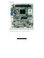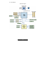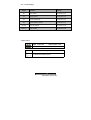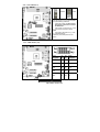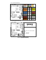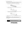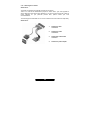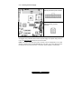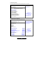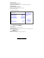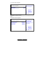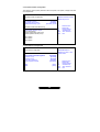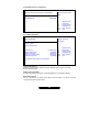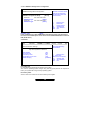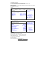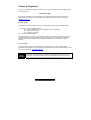
1
Toledo i3100
///
S5207
Revision 1.0
Copyright
Copyright © TYAN Computer Corporation, 2007-2008. All rights reserved. No part of this
manual may be reproduced or translated without prior written consent from TYAN
Computer Corp.
Trademark
All registered and unregistered trademarks and company names contained in this manual
are property of their respective owners including, but not limited to the following.
TYAN is trademark of TYAN Computer Corporation.
Intel and combinations thereof are trademarks of Intel Corporation.
AMI BIOS are trademarks of American Megatrends Incorporated.
Microsoft, Windows are trademarks of Microsoft Corporation.
Notice
Information contained in this document is furnished by TYAN Computer Corporation and
has been reviewed for accuracy and reliability prior to printing. TYAN assumes no liability
whatsoever, and disclaims any express or implied warranty, relating to sale and/or use of
TYAN products including liability or warranties relating to fitness for a particular purpose or
merchantability. TYAN retains the right to make changes to product descriptions and/or
specifications at any time, without notice. In no event will TYAN be held liable for any direct
or indirect, incidental or consequential damage, loss of use, loss of data or other malady
resulting from errors or inaccuracies of information contained in this document.
This manual is not validated at the time of print, subject to change. Please refer to our
website of www.tyan.com for the latest update.
1
http://www.TYAN.com
Table of Contents
Before you begin………………………………………………………………………………
Check the box contents!
Chapter 1: Introduction
1.00
Congratulations………………………………………………….………………
1.01
Hardware Specifications………………………………………………………..
1.02
Software Specifications……………………………………………………….…
Chapter 2: Board Installation
2.00
Board Image………………………………………………………..……………
2.01
Block Diagram…………………………………………………………….…..…
2.02
Board Parts, Jumpers and Connectors…………………………….………....
2.03
Jumper Settings………………………………………………………….……...
2.04
Clear CMOS (JP1)………………………………………………..………..……
2.05
COM2 Header (J15)…………………………………………………..…………
2.06
Front Panel Header (J25)………………………………………………………
2.07
System Speaker Header (J29)………………………………………..…….….
2.08
LAN LED Headers (JP5,JP6,JP7,JP8)……………………………………….
2.09
FAN Headers (FAN1, FAN2, FAN3)……………………………..…….……
2.10
Tips on Installing Motherboard in Chassis……………………………..…….
2.11
Installing the Processor(s)…………………………………………………..…
2.12
Heatsink Installation Procedures……………………………..........................
2.13
Installing the Memory………………………………………………..……….…
2.14
Attaching Drive Cables…………………………………………………………
2.15
Installing Add-in Cards…………………………………………………………
2.16
Connecting External Devices……………………………...............................
2.17
Installing the Power Supply……………………………………………………
2.18
Finishing up……………………………………………....................................
Chapter 3: BIOS Setup
3.1
About the BIOS……………………………………………………………….…
3.1.1
Setup Basics…………………………………………………………………….
3.1.2
Getting Help……………………………………………………………………..
3.1.3
In Case of Problems…………………………………………………………….
3.1.4
Setup Variations………………………………………………………………...
3.2
BIOS Main Menu………………………………………………………………..
3.3
BIOS Advanced Menu……………….…………………………………............
3.3.1
Advanced CPU Configuration………………………………………………….
3.3.2
Advanced IDE Configuration…………………………………………..............
3.3.3
Super I/O Configuration...………………………………………………………
3.3.4
ACPI Configuration………………….………………………………………….
3.3.5
AHCI Configuration………………………….………………………………….
3.3.6
APM Configuration………………………………………………………..........
3.3.7
Event Log Configuration……………………………………………………….
3.3.8
Hardware Health Configuration………………………………………….........
3.3.9
PCI Express Configuration…………………………………………………….
3.3.10
Remote Access Configuration…………………………………………………
3.3.11
USB Configuration………………………………………………………...........
3.4
PCI/PNP…………………………………………………………………………
3.5
Boot…………………………………………....................................................
3.6
Security…………………………………………………………………………...
3.7
Chipset……………………………………………………………………………
3.8
Exit…………………………………………………………………………………
Chapter 4: Diagnostics
4.0
Beep Code……………………….………………………………………………
4.1
Flash Utility…………………………..…………………………………………..
Glossary……………………………………………………………………………………….
2
http://www.TYAN.com
3
.
4
4
5
7
8
9
10
11
11
12
12
13
14
15
17
18
20
22
23
24
25
26
27
27
27
28
28
29
30
30
31
32
32
34
34
35
36
36
37
37
38
39
40
40
41
43
43
44
Before you begin…
Check the box contents!
The retail motherboard package should contain the following:
1 x S5207 motherboard
6 x SATA cables
3 x SATA Power Adapters
1 x I/O shielding
1 x TYAN Driver CD
1 x S5207 User’s Manual
1 x S5207 Quick Reference Guide
If any of these items are missing, please contact your vendor/dealer for replacement before
continuing with the installation process.
3
http://www.TYAN.com
Chapter 1: Introduction
1.00 – Congratulations!
®
You are now the owner of the S5207 low-power Intel processor solution. The S5207 is a flexible
®
®
Intel platform for multiple applications, based on the Intel 3100 chipset. This motherboard is
designed to support the Intel ® Core™ Duo and Intel® Celeron M processor (Yonah); Intel ®
Core™ 2 Duo (Merom) processor and up to 4GB of registered DDR2-400 DIMM. This motherboard
features a Flex ATX form factor, 4 USB ports, Dual Gigabit Ethernet port, one video port, 6 SATA
ports. The S5207 offers exceptional performance and versatility for all your server platform needs.
Remember to visit TYAN’s Website at http://www.tyan.com. There you can find information on all of
TYAN’s products with FAQs, distributors list and BIOS setting explanations.
1.01 – Hardware Specifications
Processor
One mPGA479 socket
Supports Intel ® Core™ Duo and Intel®
Celeron M processor (Yonah); Intel ®
Core™ 2 Duo Processor (Merom) in
FC-PGA (Flip-Chip Pin Grid Array)
package
- 533/667 MHz FSB support
- Onboard IMVP-IV CPU voltage regulation
-
Chipset
®
Intel 3100 chipset
Super I/O chip: SMSC SCH5017
Integrated Video Controller
®
ATI ES1000
32-bit PCI Interface
32MB frame buffer memory
-
Integrated LAN Controllers
Two Intel 82573L 10/100/1000
Gigabit LAN
- Two side-by-side RJ45 with LEDs
-
System Management
Integrated H/W monitoring functions
in Super I/O chip
- One 4-pin CPU fan header with auto
fan control and two 4-pin system fan
headers.
- Temperature and voltage monitoring
- Watchdog timer
-
-
Memory
Two DDR2-400 DIMM sockets
Up to 4GB of Reg/ECC DDR2-400
memory modules
-
Expansion Slots
(2) PCI Express x8 slots (w/ x4 signals)
BIOS
®
AMI BIOS on 8Mb Flash ROM
Supports ACPI
Auto detection of memory size
Auto-configuration of hard disk types
Multiple boot options including PXE
Power Management:S1, S3, S4 and
S5.
-
-
Integrated I/O
Two USB 2.0 (vertical) ports
Six integrated SATA ports up to 1.5GB/s
One 18-pin TYFP header.
One 9-pin serial port (pin header)
-
Back Panel I/O ports
One PS/2 keyboard & mouse port
Two stacked USB 2.0 ports
One 9-pin UART serial port
One 15-pin VGA port
Two RJ45 10/100/1000 Base-T ports w/
activity LED
Form Factor
Flex ATX (9” x 7.5”)
ATX (20-pin + 4-pin) power
connectors
-
-
4
http://www.TYAN.com
Integrated SATA (From Intel 3100)
Six integrated SATA ports up to 1.5Gbit/s
Supports AHCI mode
-
Regulatory
FCC Class B (DoC)
European Community CE
(Declaration of Conformity)
-
Software Specifications
OS (Operating System) Support
Windows XP Pro 32-bit + Sp2
Windows XP Pro 64-bit + Sp1
Windows Server 2003 32-bit + Sp1
Windows Server 2003 64-bit + R2
Vista Home Basic and Home Premium 32-bit
Vista Business 32-bit
Vista Ultimate 32-bit
TYAN reserves the right to add support or discontinue support for any OS with or without
notice.
5
http://www.TYAN.com
Chapter 2: Board Installation
Installation
You are now ready to install your motherboard. The mounting-hole pattern of the S5207 matches
the Flex ATX specification. Before continuing with installation, confirm that your chassis supports
the Flex ATX motherboard.
How to install our products properly…. the first time!
The first thing you should do is to read this user’s manual because the important information
contained will make configuration and setup much easier. Here are some precautions you should
take when installing your motherboard:
(1)
(2)
(3)
(4)
(5)
Ground yourself properly before removing your motherboard from the antistatic bag.
Unplug the power from your computer power supply and then touch a safely grounded
object to release static charge (i.e. power supply case). For the safest conditions, Tyan
recommends wearing a static safety wrist strap.
Hold the motherboard by its edges and do not touch the bottom of the board, or flex the
board in any way.
Avoid touching the motherboard components, IC chips, connectors, memory modules,
and leads.
Place the motherboard on a grounded antistatic surface or on the antistatic bag that the
board was shipped in.
Inspect the board for damage.
The following pages include details on how to install your motherboard into your chassis, as well as
installing the processor, memory, disk drives and cables.
NOTE
DO NOT APPLY POWER TO THE BOARD IF IT HAS BEEN DAMAGED
6
http://www.TYAN.com
2.00 – Board Image
This picture is representative of the latest board revision available at the time of
publishing. The board you receive may or may not look exactly like the picture above.
The following page includes details on the vital components of this motherboard.
7
http://www.TYAN.com
2.01 – Block Diagram
S5207 Block Diagram
8
http://www.TYAN.com
2.02 – Board Parts, Jumpers and Connectors
This jumper diagram is representative of the latest board revision available at the time of
publishing. The board you receive may not look exactly like the diagram above.
9
http://www.TYAN.com
2.03 – Jumper Settings
Jumper
Function
Settings
JP1
Clear CMOS
See Section 2.04
J15
COM2 Header
See Section 2.05
J25
Front Panel Header
See Section 2.06
J29
System Speaker Header
See Section 2.07
JP5,JP6,
JP7,JP8
LAN LED Header
See Section 2.08
FAN1,2,3
FAN Headers
See Section 2.09
Jumper Legend
OPEN - Jumper OFF
Without jumper cover
CLOSED - Jumper ON
With jumper cover
To indicate the location of pin-1
To indicate the location of pin-1
10
http://www.TYAN.com
2.04 – Clear CMOS (JP1)
Pin_3
Pin_3
Default
Clear
Pin_1
Pin_1
You can reset the CMOS settings by
using this jumper or if you have forgotten
your system/setup password.
Power off system and disconnect
both power connectors from the
motherboard
Use jumper cap to close Pin_2 and
Pin_3 for several seconds to Clear
CMOS
Put jumper cap back to Pin_1 and
Pin_2 (default setting)
Reconnect power and power on the
system
2.05 – COM2 Header (J15)
Signal
Description
Pin
#
Pin
#
DCD
1
2
DSR
RXD
3
4
RTS
TXD
5
6
CTS
DTR
7
8
RI
GND
9
10
NA
11
http://www.TYAN.com
Signal
Description
2.06 – Front Panel Header (J25)
Pin #
Pin#
HDD_
LED+
1
2
PWR_
LED+
HDD_
LED-
3
4
PWR_
LED-
GND
5
6
PWR S/W
RESET S/W
7
8
GND
GND
9
10
NC
NC
11
12
GND
5VSB
13
14
KEY
SMBusDATA
15
16
GND
SMBusCLK
17
18
INTRUDER#
Signal
Signal
2.07– System Speaker Header (J29)
Pin 1 and Pin 4 for an external speaker
header
Pin 1: +5Vdc power
Pin 4: SPK_BUZZ
12
http://www.TYAN.com
2.08 – LAN LED Headers (JP5, JP6, JP7, JP8)
JP5
LAN1 Activity LED Header
JP5 is for connecting an external
LED to indicate LAN1/2 LINK and
ACTIVITY. The behavior of this
LED is the same as LAN1/2 RJ45
LED2:
Pin 1: LED+
Pin 2: LEDJP6
LAN1 Speed LED Header
JP6 is for connecting an external
LED to indicate LAN1/2 SPEED.
The behavior of this LED is the
same as LAN1/2 RJ45 LED1:
Pin 1: 100 Mbps- (Low Active)
Pin 2: 1000 Mbps- (Low Active)
JP7
LAN2 Activity LED Header
JP7 is for connecting an external
LED to indicate LAN1/2 LINK and
ACTIVITY. The behavior of this
LED is the same as LAN1/2 RJ45
LED2:
Pin 1: LED+
Pin 2: LEDJP8
The external LED’s for JP6 and JP8 can be either
bi-color or single-color LED.
For a single-color LED to indicate 1000Mbps
SPEED, connect Pin 1 to LED+ and Pin 2 to LED-.
LAN2 Speed LED Header
JP8 is for connecting an external
LED to indicate LAN1/2 SPEED.
The behavior of this LED is the
same as LAN1/2 RJ45 LED1:
Pin 1: 100 Mbps- (Low Active)
Pin 2: 1000 Mbps- (Low Active)
13
http://www.TYAN.com
2.09 – FAN Headers (FAN1, FAN2, FAN3)
Use these headers to connect the
3-pin or 4-pin cooling fans to your
motherboard to keep the system
stable and reliable.
These connectors support the
tachometer monitoring. FAN1
supports auto fan speed control.
FAN1: CPUFAN (4-pin)
FAN2,FAN3:System FAN (4-pin)
14
http://www.TYAN.com
2.10 – Tips on Installing the Motherboard in Chassis
Before installing your motherboard, make sure your chassis has the necessary
motherboard support studs installed. These studs are usually metal and are gold in color.
Usually, the chassis manufacturer will pre-install the support studs. If you’re unsure of stud
placement, simply lay the motherboard inside the chassis and align the screw holes of the
motherboard to the studs inside the case. If there are any studs missing, you will know
right away since the motherboard will not be able to be securely installed.
S5207 Mounting Hole Placement
15
http://www.TYAN.com
Some chassis include plastic studs instead of metal. Although the plastic studs are usable,
Tyan recommends using metal studs with screws that will fasten the motherboard more
securely in place.
Below is a chart detailing what the most common motherboard studs look like and how
they should be installed.
TIP: Use metal studs if possible, as they hold the motherboard into place more securely
than plastic standoffs.
16
http://www.TYAN.com
2.11 – Installing the Processor
Your S5207 supports Intel ® Core™ Duo and Intel® Celeron M processor (Yonah); Intel ®
Core™ 2 Duo processor (Merom) in FC-PGA (Flip-Chip Pin Grid Array) package.
Only Intel ® processors are certified and supported with this motherboard. Refer to
the Tyan website for further details: www.tyan.com
Processor Installation
The processor should be installed carefully. Make sure you are wearing an antistatic strap
and handle the processor as little as possible.
Follow these instructions to install your processor
1.
For Pin Grid Array (PGA) sockets, look at the bottom of the processor to locate
which corner of the processor does not have a PIN in it.
2.
In order to insert the processor into the socket, line up the corner that does not
have a pin and insert the processor into the socket.
WARNING:
Do NOT force the pins of the processor
into the socket, as it may cause damage
to the processor. Insertion of the
processor should be smooth and gentle,
when aligned correctly.
17
http://www.TYAN.com
3.
Hold down the processor with your finger and use a small flat head screw driver to
turn the locking screw clockwise 180 degrees, to the locked position. Next to the
sides of the screw on the socket, there are diagrams of a closed lock and an open
lock indicating if the socket is locked or unlocked.
2.12 Heatsink Installation Procedures
After you have installed the processor, you should proceed to installing the heatsink.
Heatsink will ensure that the processor does not overheat and continues to operate at
maximum performance for as long as you own it.
1.
Mount the self-adhesive square metal bracket on the bottom of the board underneath
the processor socket. This bracket lines up with the four holes making a square
around the processor and provides the nut for the fan screws to plug into.
Note: This CPU back bracket usually comes with CPU fan/heatsink. Both bracket and
heatsink are not included in this motherboard accessories.
18
http://www.TYAN.com
2.
Place the fan on top of the processor and screw it into the bracket as shown in
Finishing Installing the Heatsink
After you finish installing the heatsink onto the processor and socket, attach the end wire of
the fan (which should already be attached to the heatsink) to the motherboard.
After you’re finished installing all the fans you
can connect your drives (hard drives, CD-ROM
drives, etc.) to your motherboard.
19
http://www.TYAN.com
2.13 – Installing the Memory
Before attempting to install any memory, make sure that the memory you have is
compatible with the motherboard as well as the processor. A Critical aspect to any system
build is whether you’re using the recommended memory for your specific motherboard. For
compatibility information, please check Tyan’s web site at: www.tyan.com
The following diagram shows common types of DDR2 RAM modules:
Here are a few key points to note before installing memory into your S5207:
•
•
•
•
Only Reg/ECC DDR2 400 MHz memory modules are supported.
DIMM2 (the DIMM connector closest to the edge of the board, furthest from the
CPU socket) must be installed for the system to turn on and POST (power on self
test).
ECC support.
S5207 supports up to 4GB.
20
http://www.TYAN.com
Memory Installation Procedure
When you install the memory modules, make sure the module aligns properly with the
memory slot. The modules are keyed to ensure that it is inserted only one way. The
method of installing memory modules are detailed by the following diagrams.
1.
Press the locking levers in the direction shown in the following illustration.
2.
Align the memory module with the socket. The memory module is keyed to fit only
one way in the socket.
3.
Seat the module firmly into the socket by gently pressing down until it sits flush
with the socket. The locking levers pop up into place.
To remove the memory module, simply push the latches outwards until the memory
module pops up.
TIP: When installing memory, a module may require a considerable amount of force to
seat properly, although this is very rare. To avoid bending and damaging your
motherboard, place it on its anti-static bag and onto a flat surface, and then proceed with
memory installation.
NOTE
YOU MUST ALWAYS unplug the power connector to the
motherboard before performing system hardware changes, to
avoid damaging the board or expansion device.
21
http://www.TYAN.com
2.14 – Attaching Drive Cables
SATA Drives
The S5207 is equipped with 6 Serial ATA (SATA) connectors.
There is no need to set Master/Slave jumpers on SATA drives. Tyan has supplied six
SATA cables and three SATA power adapters. If you did not receive the proper cables or
power adapters for your particular product SKU, please contact your local
vendor/distributor.
The following picture illustrates how to connect a SATA drive and a SAS drive respectively.
SATA Drives
1.
SATA drive cable
connection
2.
SATA drive power
connection
3.
SATA cable motherboard
connector
4.
SATA drive power adapter
22
http://www.TYAN.com
2.15 – Installing Add-In Cards
Before installing add-in cards, it’s helpful to know if they are fully compatible with your
motherboard. For this reason, we’ve provided the diagrams below, showing the compatible
slots that may appear on your motherboard. Not all of the slots shown will necessarily
appear on your motherboard, however, there will be combinations of what you see here.
PCI-E x 8 Slot
Simply find the appropriate slot for your add-in card and insert the card firmly. Do not force
any add-in cards (or anything else) into any slots if they won’t seat in place. It’s better to try
another slot or return the faulty card rather than damaging both the motherboard and the
add-in card.
TIP: It’s good practice to install add-in cards in a staggered manner, rather than directly
adjacent to each other. This allows air to circulate within the chassis more easily, providing
improved cooling for all installed devices.
NOTE
YOU MUST ALWAYS unplug the power connector to the motherboard
before performing system hardware changes, to avoid damaging the
board or expansion device.
23
http://www.TYAN.com
2.16 – Connecting External Devices
The following diagrams will detail the rear port stack for this S5207 motherboard:
PS/2
Mouse/Keyboard
Stacked
USB2.0 Ports
Serial Port
VGA Port
Gigabit
Ethernet
This picture is representative of the latest board revision available at the time of
publishing. The board you receive may or may not look exactly like the above
picture.
Peripheral devices can be plugged straight into any of these ports but software may be
required to complete the installation.
24
http://www.TYAN.com
2.17 – Installing the Power Supply
PW1: 20-pin ATX main power connector
PW2: 2x2 pin ATX_12V power
connector
We suggest using a standard off-the-shelf ATX power supply with a power rating of 350 W.
Look to the www.tyan.com website for further information.
NOTE: The S5207 peripheral drive power connector must be independent of any other
devices. A device such as a DVD/CD-ROM drive, hard drive, or any other devices cannot
be attached onto the same power line. If connected, system stability is compromised.
25
http://www.TYAN.com
2.18 – Finishing Up
Congratulations on making it this far! You’re finished setting up the hardware aspect of
your computer. Before closing up your chassis, make sure that all cables and wires are
connected properly, especially IDE cables and most importantly, jumpers. You may have
difficulty powering on your system if the motherboard jumpers are not set correctly.
In the rare circumstance that you have experienced difficulty, you can find help by asking
your vendor for assistance. If they are not available for assistance, please find setup
information and documentation online at our website or by calling your vendor’s support
line.
26
http://www.TYAN.com
Chapter 3: BIOS Setup
3.1. About the BIOS
The BIOS is the basic input/output system, the firmware on the motherboard that enables
your hardware to interface with your software. The BIOS determines what a computer can
do without accessing programs from a disk. The BIOS contains all the code required to
control the keyboard, display screen, disk drives, serial communications, and a number of
miscellaneous functions. This chapter describes the various BIOS settings that can be
used to configure your system.
The BIOS section of this manual is subject to change without notice and is provided for
reference purposes only. The settings and configurations of the BIOS are current at the
time of print and are subject to change, and therefore may not match exactly what is
displayed on screen.
This section describes the BIOS setup program. The setup program lets you modify basic
configuration settings. The settings are then stored in a dedicated, battery-backed memory
(called NVRAM) that retains the information even when the power is turned off.
To start the BIOS setup utility:
1. Turn on or reboot your system.
2. Press <Del> during POST (F4 on remote console) to start the BIOS setup utility.
3.1.1 Setup Basics
The table below shows how to navigate in the setup program using the keyboard.
Key
Tab
Left/Right Arrow Keys
Up/Down Arrow Keys
Enter
PgUp/PgDn Keys
Function
Moves from one selection to the next
Changes from one menu to the next
Moves between selections
Opens highlighted section
Changes settings.
3.1.2 Getting Help
Pressing [F1] will display a small help window that describes the appropriate
keys to use and the possible selections for the highlighted item. To exit the Help Window,
press [ESC] or the [F1] key again.
27
http://www.TYAN.com
3.1.3 In Case of Problems
If you have trouble booting your computer after making and saving the changes with the
BIOS setup program, you can restart the computer by holding the power button down until
the computer shuts off (usually within 4 seconds); resetting by pressing CTRL-ALT-DEL; or
clearing the CMOS.
The best advice is to only alter settings that you thoroughly understand. In particular, do
not change settings in the Chipset section unless you are absolutely sure of what you are
doing. The Chipset defaults have been carefully chosen either by TYAN or your system
manufacturer for best performance and reliability. Even a seemingly small change to the
Chipset setup options may cause the system to become unstable or unusable.
3.1.4 Setup Variations
Not all systems have the same BIOS setup layout or options. While the basic look and
function of the BIOS setup remains more or less the same for most systems, the
appearance of your Setup screen may differ from the charts shown in this section. Each
system design and chipset combination requires a custom configuration. In addition, the
final appearance of the Setup program depends on the system designer. Your system
designer may decide that certain items should not be available for user configuration, and
remove them from the BIOS setup program.
NOTE: The following pages provide the details of BIOS menu. Please be noticed that the
BIOS menu are continually changing due to the BIOS updating. The BIOS menu provided
are the most updated ones when this manual is written. Please visit Tyan’s website at
http://www.tyan.com for the information of BIOS updating.
28
http://www.TYAN.com
3.2 BIOS Main Menu
In this section, you can alter general features such as the date and time.
Note that the options listed below are for options that can directly be changed within the
Main Setup screen.
Main
Advanced
BIOS Setup Utility
PCIPnP
Boot
System Overview
AMI BIOS
Version:
Build Date:
ID:
Security
Chipset
Exit
Use [Enter], [TAB] or
[SHIFT-TAB] to select a
field.
xx.xx.xx
xx/xx/xx
xxxxxxxx
Use [+] or [-] to configure
system Time.
Processor
Speed:
Count:
System Memory
Size:
System Time
System Date
[HH:MM:SS]
[MM/DD/YYYY]
BIOS Version
This displays the version of BIOS.
BIOS Build Date
This displays the date of BIOS build.
System Time / Date setup
System Time: Adjusts the system clock.
HH Hours (24hr. format)
MM Minutes
SS Seconds
System Date: Adjusts the system date.
MM Months
DD Days
YYYY
Years
Processor
This displays the CPU model and frequency.
System Memory
This displays the Memory volume.
29
http://www.TYAN.com
←
Select Screen
↑↓ Select Item
+Change Field
TAB Select Field
F1
General Help
F10
Save and Exit
F9
Setup Defaults
Esc
Exit
3.3 BIOS Advanced Menu
This section facilitates configuring advanced BIOS options for your system.
Main
Advanced
BIOS Setup Utility
PCIPnP
Boot
Advanced Settings
Security
Chipset
Exit
Configure CPU
WARNING: Setting wrong values in below sections
may cause system to malfunction.
X CPU Configuration
X IDE Configuration
X Super IO Configuration
X ACPI Configuration
X AHCI Configuration
X APM Configuration
X Event Log Configuration
X Hardware Health Configuration
X PCI Express Configuration
X Remote Access Configuration
X USB Configuration
←
Select Screen
↑↓ Select Item
Enter Go to Sub Screen
F1
General Help
F10
Save and Exit
Esc
Exit
3.3.1 Advanced CPU Configuration
This section allows you to fine-tune the processor options.
Advanced
Configure advanced CPU settings
Module Version: xx.xx
This should be enabled in
order to enable or disable
the Hardware Prefetcher
Disable Feature.
Manufacturer: Intel
Frequency:
FSB Speed:
Cache L1:
Cache L2:
Ratio Actual Value:
Max CPUID Value Limit
Vanderpool Technology
Execute Disable Bit
Core Multi-Processing
DTS-based Thermal Management
DTS Calibration
Intel® SpeedStep™ tech.
Intel ® C-State tech.
C1 Config.
C2 Config.
C3 Config.
C4 Config.
[Disabled]
[Enabled]
[Enabled]
[Enabled]
[Enabled]
[Enabled]
[Disabled]
[Enhanced]
[Standard]
[Standard]
[Disabled]
30
http://www.TYAN.com
←
Select Screen
↑↓ Select Item
+Change Option
F1
General Help
F10
Save and Exit
Esc
Exit
Core Multi-Processing
When disabled, diable one execution core.
DTS-based Thermal Management
Enable/Disable Thermal Management utilizing the CPU’s Digital Thermal Sensor.
Intel® SpeedStep tech
Maximum: CPU speed is set to maximum.
Minimum: CPU speed is set to minimum.
Automatic: CPU speed controlled by operating system.
Disabled: Default CPU speed.
3.3.2 Advanced IDE Configuration
Advanced
IDE Configuration
ATA/IDE Configuration
Configure SATA as
[Enhanced]
[IDE]
XPrimary IDE Master
XPrimary IDE Slave
XSecondary IDE Master
XSecondary IDE Slave
[Not Detected]
[Not Detected]
[Not Detected]
[Not Detected]
Hard Disk Write Protect
IDE Detect Time Out
[Disabled]
[35]
Select whether the IDE
channels should be
initialized in Compatible or
Enhanced mode of
operation.
←
Select Screen
↑↓ Select Item
+Change Option
F1
General Help
F10
Save and Exit
Esc
Exit
ATA/IDE Configuration
This defines the operation mode of IDE channels.
Disabled/ Compatible/ Enhanced
Configure SATA as
Select legacy IDE or AHCI as the SATA interface.
Hard Disk Write Protect
This feature is used to Disable/Enable device write protection. This will be effective only if
device is accessed through BIOS.
Disabled/ Enabled
IDE Detect Time Out (Sec)
Select the time out value for detecting ATA/ATAPI device(s).
31
http://www.TYAN.com
3.3.3 Super I/O Configuration
This setting allows you to configure Serial Port1 Base Addresses.
Disabled/ 3F8/IRQ4 / 3E8/IRQ4 / 2E8/IRQ3
This setting allows you to configure Serial Port2 Base Addresses.
Disabled/ 2F8/IRQ3 / 3E8/IRQ4 / 2E8/IRQ3
Advanced
Configure SCH5017 Super IO Chipset
Serial Port1 Address
Serial Port2 Address
Allow BIOS to Select Serial
Port1 Base Addresses.
[3F8/IRQ4]
[2F8/IRQ3]
←
Select Screen
↑↓ Select Item
+Change Option
F1
General Help
F10
Save and Exit
Esc
Exit
3.3.4 ACPI Configuration
Advanced
ACPI Settings
General ACPI
Configuration settings
XGeneral ACPI Configuration
XAdvanced ACPI Configuration
XChipset ACPI Configuration
←
Select Screen
↑↓ Select Item
Enter Go to Sub Screen.
F1
General Help
F10
Save and Exit
Esc
Exit
32
http://www.TYAN.com
3.3.4.1 General ACPI Configuration
Advanced
General ACPI Configuration
Select the ACPI state used
for System Suspend.
Suspend mode
Repost Video on S3 Resume
[Auto]
[No]
←
↑↓
+F1
F10
Esc
Select Screen
Select Item
Change Option
General Help
Save and Exit
Exit
Suspend mode: S1 (POS)/ S3(STR)/Auto
Repost Video on S3 Resume: Determines whether to invoke VGA BIOS post on S3/STR
resume.
3.3.4.2 Advanced ACPI Configuration
Advanced
Advanced ACPI Configuration
ACPI Version Features
ACPI APIC support
AMI OEMB table
Headless mode
[ACPI v2.0]
[Enabled]
[Enabled]
[Disabled]
Enable RSDP pointers to
64-bit Fixed System
Description Tables.
Different ACPI version has
some addition.
←
↑↓
+F1
F10
Esc
33
http://www.TYAN.com
Select Screen
Select Item
Change Option
General Help
Save and Exit
Exit
3.3.4.3 Chipset ACPI Configuration
Advanced
South Bridge ACPI configuration
Enable/Disable APIC ACPI
SCI IRQ.
APIC ACPI SCI IRQ
USB Device Wakeup From S3/S4
[Disabled]
[Enabled]
←
↑↓
+F1
F10
Esc
Select Screen
Select Item
Change Option
General Help
Save and Exit
Exit
3.3.5 AHCI Configuration
Advanced
AHCI Settings
AHCI CD/DVD Boot Time out
[15]
XAHCI Port0 [Not Detected]
XAHCI Port1 [Not Detected]
XAHCI Port2 [Not Detected]
XAHCI Port3 [Not Detected]
XAHCI Port4 [Not Detected]
XAHCI Port5 [Not Detected]
Some SATA CD/DVD in
AHCI mode need to wait
ready longer.
←
↑↓
+F1
F10
Esc
Select Screen
Select Item
Change Option
General Help
Save and Exit
Exit
3.3.6 APM Configuration
Advanced
APM Configuration
Power Management/APM
Video Power Down Mode
Hard Disk Power Down Mode
Suspend Time Out
Throttle Slow Clock Ratio
Keyboard & PS/2 Mouse
Power Button Mode
[Enabled]
[Suspend]
[Suspend]
[Disabled]
[50%]
[Monitor]
[On/Off]
Advance Resume Event Controls
Resume On RTC Alarm
[Disabled]
34
http://www.TYAN.com
Enable/Disable APM
←
↑↓
+F1
F10
Esc
Select Screen
Select Item
Change Option
General Help
Save and Exit
Exit
Video Power Down Mode
Power Down Video in Suspend or Standby Mode.
Hard Disk Power Down Mode
Power Down Hard Disk in Suspend or Standby Mode.
Suspend Time Out
Go into Suspend in the specified Time.
Throttle Slow Clock Ratio
Select the duty cycle in throttle mode.
Power Button Mode
Go into on/off, or Suspend when Power Button is pressed.
Resume on PME#
Disable/Enable PME to generate a wake Event.
Resume on RTC Alarm
Disable/Enable RTC to generate a wake Event.
3.3.7 Event Log Configuration
Advanced
Event Logging details
View all unread events on
the Event Log.
View Event Log
Mark all events as read
Clear Event Log
←
↑↓
+F1
F10
Esc
35
http://www.TYAN.com
Select Screen
Select Item
Change Option
General Help
Save and Exit
Exit
3.3.8 Hardware Health Configuration
This displays critical system parameters like CPU speed, fan speeds, voltage levels and
CPU temperature.
Advanced
Hardware Health Configuration
Enables Hardware Health
Monitoring Device
H/W Health Function
Auto FAN Power Control
PWM Minimal Duty Cycle
[Enabled]
[Enabled]
[30% Duty Cycle]
←
↑↓
+F1
F10
Esc
Hardware Health Event Monitoring
XMainboard Voltages Report
CPU Temperature:
Ambient (Near BIOS chip) Temp:
Ambient (WhitmoreLake) Temp:
Select Screen
Select Item
Change Option
General Help
Save and Exit
Exit
FAN1 Speed
FAN2 Speed
FAN3 Speed
3.3.9 PCI Express Configuration
Advanced
PCI Express Configuration
Enable/Disable PCI
Express L0s and L1 link
power states.
Active State Power-Management
PCIe Slot 1 (x4)
PCIe Slot 2 (x4)
PCIe Jitter Tolerance
PCIe Compliance mode
[Disabled]
[Enabled]
[Enabled]
[Enabled]
[Disabled]
LAN1
LAN2
[Auto]
[Auto]
36
http://www.TYAN.com
←
↑↓
+F1
F10
Esc
Select Screen
Select Item
Change Option
General Help
Save and Exit
Exit
3.3.10 Remote Access Configuration
Advanced
Configure Remote Access type and parameters
Remote Access
Select Remote Access
type.
[Disabled]
←
↑↓
+F1
F10
Esc
Select Screen
Select Item
Change Option
General Help
Save and Exit
Exit
3.3.11 USB Configuration
Advanced
USB Configuration
Enable USB host
controllers
Module Version
USB Device Enabled:
USB Function
Legacy USB support
USB 2.0 Controller
USB 2.0 Controller mode
BIOS EHCI Hand-off
[4 USB Ports]
[Enabled]
[Enabled]
[HiSpeed]
[Enabled]
←
↑↓
+F1
F10
Esc
Select Screen
Select Item
Change Option
General Help
Save and Exit
Exit
XUSB Mass Storage Device Configuration
Legacy USB Support
Enables support for legacy USB. Auto option disables legacy support if no USB
Devices are connected.
USB 2.0 Controller Mode
Configure the USB 2.0 Controller in HiSpeed(480Mbps) or FullSpeed (12Mbps)
BIOS EHCI Hand-off
This is a workaround for OSes without EHCI hand-off support. The EHCI ownership
change should claim by EHCI driver.
37
http://www.TYAN.com
3.3.11.1 USB Mass Storage Device Configuration
Advanced
USB Mass Storage Device Configuration
USB Mass Storage Reset Delay
Device #1
Emulation Type
Device #2
Emulation Type
[20 sec]
ATP ATP Petito UFD
[Auto]
ATP ATP Petito UFD
[Auto]
Number of Seconds POST
waits for the USB mass
storage device after start
unit command.
←
↑↓
+F1
F10
Esc
Select Screen
Select Item
Change Option
General Help
Save and Exit
Exit
Emulation Type
[Auto]
If Auto, USB device less than 530MB will be emulated as Floppy and remaining as
hard drive. Forced FDD option can be used to force a HDD formatted drive to boot as
FDD (Ex.ZIP drive)
3.4 PCI/PnP
Main
Advanced
BIOS Setup Utility
PCIPnP
Boot
Advanced PCI/PnP Settings
WARNING: Setting wrong values in below sections
may cause system to malfunction.
Clear NVRAM
Plug & Play O/S
PCI Latency Timer
Allocate IRQ TO PCI VGA
Palette Snooping
[No]
[No]
[64]
[Yes]
[Disabled]
Security
Chipset
Exit
Clear NVRAM during
System Boot.
←
Select Screen
↑↓ Select Item
Enter Go to Sub Screen
F1
General Help
F10
Save and Exit
Esc
Exit
Plug & Play O/S
No: Lets the BIOS configure all the devices in the system.
Yes: Lets the operating system configure Plug and Play (PnP) devices not required for
boot if your system has a Plug and Play operating system
PCI Latency Timer
Value in units of PCI clocks for PCI device latency timer register.
38
http://www.TYAN.com
Allocate IRQ to PCI VGA
Yes: Assign IRQ to PCI VGA card if card requests IRQ.
No: Does not assign IRQ to PCI VGA card even if card requests an IRQ.
Palette Snooping
Enabled: informs the PCI devices that an ISA graphics device is installed in the system so
the card will function correctly.
3.5 Boot
Main
Advanced
BIOS Setup Utility
PCIPnP
Boot
Security
Boot Settings
Chipset
Exit
Configure Settings during
System Boot.
XBoot Settings Configuration
st
1 Boot Device
nd
2 Boot Device
rd
3 Boot Device
th
4 Boot Device
[USB:ATP ATP Petito]
[USB:ATP ATP Petito]
[Network: IBA GE slo]
[Network: IBA GE slo]
←
Select Screen
↑↓ Select Item
Enter Go to Sub Screen
F1
General Help
F10
Save and Exit
Esc
Exit
3.5.1 Boot Settings Configuration
Boot
Boot Settings Configuration
Quick Boot
Quiet Boot
AddOn ROM Display Mode
Bootup Num-Lock
PS/2 Mouse Support
Wait for F1 if Error
Hit “DEL” Message Display
Interrupt 19 Capture
Endless Boot
Auto Eject Function
[Disabled]
[Disabled]
[Force BIOS]
[On]
[Auto]
[Enabled]
[Enabled]
[Enabled]
[Disabled]
[Disabled]
Quiet Boot
Disabled: Displays normal POST messages.
Enabled: Displays OEM Logo instead of POST messages.
AddOn ROM Display Mode Force BIOS/ Keep Current
Set display mode for Option ROM.
Interrupt 19 Capture
Enabled: Allows option roms to trap interrupt 19.
39
http://www.TYAN.com
Allow BIOS to SKIP certain
tests while booting. This
will decrease the time
needed to boot the system.
←
↑↓
+F1
F10
Esc
Select Screen
Select Item
Change Option
General Help
Save and Exit
Exit
3.6 Security
Main
Advanced
BIOS Setup Utility
PCIPnP
Boot
Security Settings
Security
Chipset
Exit
Install or change the
password.
Supervisor Password: Not Installed
User Password:
Not Installed
Change Supervisor Password
Change User Password
Boot Sector Virus Protection
[Disabled]
←
Select Screen
↑↓ Select Item
Enter Go to Sub Screen
F1
General Help
F10
Save and Exit
Esc
Exit
3.7 Chipset
Main
Advanced
BIOS Setup Utility
PCIPnP
Boot
Advanced Chipset Settings
Security
Chipset
Exit
Configure South Bridge
features.
WARNING: Setting wrong values in below sections
may cause system to malfunction.
XSouthBridge Configuration
Clock Gen, Spread Spectrum
[Enabled]
40
http://www.TYAN.com
←
Select Screen
↑↓ Select Item
Enter Go to Sub Screen
F1
General Help
F10
Save and Exit
Esc
Exit
3.7.1 Chipset
Chipset
South Bridge Chipset Configuration
Options
SMBUS Controller
SLP_S4# Min. Assertion Width
Restore on AC Power Loss
[Enabled]
Enabled
Disabled.
[1 to 2 seconds]
[Power On]
Watchdog Mode
[Disabled]
←
↑↓
+F1
F10
Esc
Select Screen
Select Item
Change Option
General Help
Save and Exit
Exit
Watchdog Mode
Post: BIOS post Watchdog, timer counting start at PowerOn, Stop at OS boot
OS: OS boot Watchdog, Start at OS boot
PowerOn: Start at PowerOn.
3.8 Exit
Exit
Exit Options
Exit system setup after
saving the changes.
Save Changes and Exit
Discard Changes and Exit
Discard Changes
F10 key ca be used for this
operation.
Load Optimal Defaults
Load Failsafe Defaults
←
↑↓
+F1
F10
Esc
Save Changes and Exit
Exit system setup after saving the changes
F10key can be used for this operation.
Discard Changes and Exit
Exit system setup without saving any changes
ESC key can be used for this operation.
Discard Changes
Discards all changes made without exiting BIOS setup.
F7 key can be used for this operation.
41
http://www.TYAN.com
Select Screen
Select Item
Change Option
General Help
Save and Exit
Exit
Load Optimal Defaults
Loads Optimal Default values for all the setup questions.
F9 key can be used for this operation.
Load Failsafe Defaults
Loads Failsafe Default values for all the setup questions.
F8 key can be used for this opera
42
http://www.TYAN.com
Chapter 4: Diagnostics
Note: if you experience problems with setting up your system, always check the following things in
the following order:
CPU, Memory, Video
By checking these items, you will most likely find out what the problem might have been when
setting up your system. For more information on troubleshooting, check the Tyan website at:
http://www.tyan.com.
4.0 Beep Codes
Fatal errors which halt the boot process are communicated through a series of audible beeps.
(1)
(2)
Memory module initialization failed
(a) memory modules might not be plugged in correct configuration
(b) wrong type of memory
(c) bad memory modules
Graphics initialization failed
Before contacting your vendor or Tyan Technical Support, be sure that you note as much as you
can about the beep code length and order that you experience. Also, be ready with information
regarding add-in cards, drives and O/S to speed the support process and come to a quicker
solution.
4.1 Flash Utility
Every BIOS file is unique for the motherboard it was designed for. For Flash Utilities, BIOS
downloads, and information on how to properly use the Flash Utility with your motherboard, please
check the Tyan web site: http://www.tyan.com
NOTE
Please be aware that by flashing your BIOS, you agree that in the event of a BIOS
flash failure, you must contact your dealer for a replacement BIOS. There are no
exceptions. Tyan does not have a policy for replacing BIOS chips directly with end
users. In no event will Tyan be held responsible for damages done by the end user.
43
http://www.TYAN.com
Appendix: Glossary
ACPI (Advanced Configuration and Power Interface): a power management specification that
allows the operating system to control the amount of power distributed to the computer’s devices.
Devices not in use can be turned off, reducing unnecessary power expenditure.
AGP (Accelerated Graphics Port): a PCI-based interface which was designed specifically for
demands of 3D graphics applications. The 32-bit AGP channel directly links the graphics controller
to the main memory. While the channel runs only at 66 MHz, it supports data transmission during
both the rising and falling ends of the clock cycle, yielding an effective speed of 133 MHz.
ATAPI (AT Attachment Packet Interface): also known as IDE or ATA; a drive implementation that
includes the disk controller on the device itself. It allows CD-ROMs and tape drives to be configured
as master or slave devices, just like HDDs.
ATX: the form factor designed to replace the AT form factor. It improves on the AT design by
rotating the board 90 degrees, so that the IDE connectors are closer to the drive bays, and the CPU
is closer to the power supply and cooling fan. The keyboard, mouse, USB, serial, and parallel ports
are built-in.
Bandwidth: refers to carrying capacity. The greater the bandwidth, the more data the bus, phone
line, or other electrical path can carry. Greater bandwidth results in greater speed.
BBS (BIOS Boot Specification): a feature within the BIOS that creates, prioritizes, and maintains a
list of all Initial Program Load (IPL) devices, and then stores that list in NVRAM. IPL devices have
the ability to load and execute an OS, as well as provide the ability to return to the BIOS if the OS
load process fails. At that point, the next IPL device is called upon to attempt loading of the OS.
BIOS (Basic Input/Output System): the program that resides in the ROM chip, which provides the
basic instructions for controlling your computer’s hardware. Both the operating system and
application software use BIOS routines to ensure compatibility.
Buffer: a portion of RAM which is used to temporarily store data; usually from an application though
it is also used when printing and in most keyboard drivers. The CPU can manipulate data in a buffer
before copying it to a disk drive. While this improves system performance (reading to or writing from
a disk drive a single time is much faster than doing so repeatedly) there is the possibility of losing
your data should the system crash. Information in a buffer is temporarily stored, not permanently
saved.
Bus: a data pathway. The term is used especially to refer to the connection between the processor
and system memory, and between the processor and PCI or ISA local buses.
Bus mastering: allows peripheral devices and IDEs to access the system memory without going
through the CPU (similar to DMA channels).
Cache: a temporary storage area for data that will be needed often by an application. Using a cache
lowers data access times since the information is stored in SRAM instead of slower DRAM. Note
that the cache is also much smaller than your regular memory: a typical cache size is 512KB, while
you may have as much as 4GB of regular memory.
Closed and open jumpers: jumpers and jumper pins are active when they are “on” or “closed”, and
inactive when they are “off” or “open”.
44
http://www.TYAN.com
CMOS (Complementary Metal-Oxide Semiconductors): chips that hold the basic startup
information for the BIOS.
COM port: another name for the serial port, which is called as such because it transmits the eight
bits of a byte of data along one wire, and receives data on another single wire (that is, the data is
transmitted in serial form, one bit after another). Parallel ports transmit the bits of a byte on eight
different wires at the same time (that is, in parallel form, eight bits at the same time).
FBDIMM (Double Data Rate): a technology designed to double the clock speed of the memory. It
activates output on both the rising and falling edge of the system clock rather than on just the rising
edge, potentially doubling output.
DIMM (Dual In-line Memory Module): faster and more capacious form of RAM than SIMMs, and
do not need to be installed in pairs.
DIMM bank: sometimes called DIMM socket because the physical slot and the logical unit are the
same. That is, one DIMM module fits into one DIMM socket, which is capable of acting as a memory
bank.
DMA (Direct Memory Access): channels that are similar to IRQs. DMA channels allow hardware
devices (like soundcards or keyboards) to access the main memory without involving the CPU. This
frees up CPU resources for other tasks. As with IRQs, it is vital that you do not double up devices on
a single line. Plug-n-Play devices will take care of this for you.
DRAM (Dynamic RAM): widely available, very affordable form of RAM which looses data if it is not
recharged regularly (every few milliseconds). This refresh requirement makes DRAM three to ten
times slower than non-recharged RAM such as SRAM.
ECC (Error Correction Code or Error Checking and Correcting): allows data to be checked for
errors during run-time. Errors can subsequently be corrected at the same time that they’re found.
EEPROM (Electrically Erasable Programmable ROM): also called Flash BIOS, it is a ROM chip
which can, unlike normal ROM, be updated. This allows you to keep up with changes in the BIOS
programs without having to buy a new chip. TYAN’s BIOS updates can be found at
http://www.tyan.com
ESCD (Extended System Configuration Data): a format for storing information about Plug-n-Play
devices in the system BIOS. This information helps properly configure the system each time it
boots.
Firmware: low-level software that controls the system hardware.
Form factor: an industry term for the size, shape, power supply type, and external connector type
of the Personal Computer Board (PCB) or motherboard. The standard form factors are the AT and
ATX.
Global timer: onboard hardware timer, such as the Real-Time Clock (RTC).
HDD: stands for Hard Disk Drive, a type of fixed drive.
H-SYNC: controls the horizontal synchronization/properties of the monitor.
TM
HyperThreading : a high speed, low latency, scalable point-to-point link for interconnecting ICs
on boards. It can be significantly faster than a PCI bus for an equivalent number of pins. It provides
the bandwidth and flexibility critical for today's networking and computing platforms while retaining
45
http://www.TYAN.com
the fundamental programming model of PCI.
IC (Integrated Circuit): the formal name for the computer chip.
IDE (Integrated Device/Drive Electronics): a simple, self-contained HDD interface. It can handle
drives up to 8.4 GB in size. Almost all IDEs sold now are in fact Enhanced IDEs (EIDEs), with
maximum capacity determined by the hardware controller.
IDE INT (IDE Interrupt): a hardware interrupt signal that goes to the IDE.
I/O (Input/Output): the connection between your computer and another piece of hardware (mouse,
keyboard, etc.)
IRQ (Interrupt Request): an electronic request that runs from a hardware device to the CPU. The
interrupt controller assigns priorities to incoming requests and delivers them to the CPU. It is
important that there is only one device hooked up to each IRQ line; doubling up devices on IRQ
lines can lock up your system. Plug-n-Play operating systems can take care of these details for you.
Latency: the amount of time that one part of a system spends waiting for another part to catch up.
This occurs most commonly when the system sends data out to a peripheral device and has to wait
for the peripheral to spread (peripherals tend to be slower than onboard system components).
NVRAM: ROM and EEPROM are both examples of Non-Volatile RAM, memory that holds its data
without power. DRAM, in contrast, is volatile.
Parallel port: transmits the bits of a byte on eight different wires at the same time.
PCI (Peripheral Component Interconnect): a 32 or 64-bit local bus (data pathway) which is faster
than the ISA bus. Local buses are those which operate within a single system (as opposed to a
network bus, which connects multiple systems).
PCI PIO (PCI Programmable Input/Output) modes: the data transfer modes used by IDE drives.
These modes use the CPU for data transfer (in contrast, DMA channels do not). PCI refers to the
type of bus used by these modes to communicate with the CPU.
PCI-to-PCI bridge: allows you to connect multiple PCI devices onto one PCI slot.
Pipeline burst SRAM: a fast secondary cache. It is used as a secondary cache because SRAM is
slower than SDRAM, but usually larger. Data is cached first to the faster primary cache, and then,
when the primary cache is full, to the slower secondary cache.
PnP (Plug-n-Play): a design standard that has become ascendant in the industry. Plug-n-Play
devices require little set-up to use. Devices and operating systems that are not Plug-n-Play require
you to reconfigure your system each time you add or change any part of your hardware.
PXE (Preboot Execution Environment): one of four components that together make up the Wired
for Management 2.0 baseline specification. PXE was designed to define a standard set of preboot
protocol services within a client with the goal of allowing networked-based booting to boot using
industry standard protocols.
RAID (Redundant Array of Independent Disks): a way for the same data to be stored in different
places on many hard drives. By using this method, the data is stored redundantly and multiple hard
drives will appear as a single drive to the operating system. RAID level 0 is known as striping, where
data is striped (or overlapped) across multiple hard drives, but offers no fault-tolerance. RAID level
1 is known as mirroring, which stores the data within at least two hard drives, but does not stripe.
RAID level 1 also allows for faster access time and fault-tolerance, since either hard drive can be
46
http://www.TYAN.com
read at the same time. RAID level 0+1 is both striping and mirroring, providing fault-tolerance,
striping, and faster access all at the same time.
RAIDIOS: RAID I/O Steering (Intel)
RAM (Random Access Memory): technically refers to a type of memory where any byte can be
accessed without touching the adjacent data and is often referred to the system’s main memory.
This memory is available to any program running on the computer.
ROM (Read-Only Memory): a storage chip which contains the BIOS; the basic instructions
required to boot the computer and start up the operating system.
SDRAM (Synchronous Dynamic RAM): called as such because it can keep two sets of memory
aFBDIMMesses open simultaneously. By transferring data alternately from one set of
aFBDIMMesses and then the other, SDRAM cuts down on the delays associated with
non-synchronous RAM, which must close one aFBDIMMess bank before opening the next.
Serial port: called as such because it transmits the eight bits of a byte of data along one wire, and
receives data on another single wire (that is, the data is transmitted in serial form, one bit after
another).
SCSI Interrupt Steering Logic (SISL): Architecture that allows a RAID controller, such as
AcceleRAID 150, 200 or 250, to implement RAID on a system board-embedded SCSI bus or a set
of SCSI busses. SISL: SCSI Interrupt Steering Logic ( LSI ) (only on LSI SCSI boards)
Sleep/Suspend mode: in this mode, all devices except the CPU shut down.
SDRAM (Static RAM): unlike DRAM, this type of RAM does not need to be refreshed in order to
prevent data loss. Thus, it is faster and more expensive.
Standby mode: in this mode, the video and hard drives shut down; all other devices continue to
operate normally.
UltraDMA-33/66/100: a fast version of the old DMA channel. UltraDMA is also called UltraATA.
Without a proper UltraDMA controller, your system cannot take advantage of higher data transfer
rates of the new UltraDMA/UltraATA hard drives.
USB (Universal Serial Bus): a versatile port. This one port type can function as a serial, parallel,
mouse, keyboard or joystick port. It is fast enough to support video transfer, and is capable of
supporting up to 127 daisy-chained peripheral devices.
VGA (Video Graphics Array): the PC video display standard
V-SYNC: controls the vertical scanning properties of the monitor.
ZCR (Zero Channel RAID): PCI card that allows a RAID card to use the onboard SCSI chip, thus
lowering cost of RAID solution
ZIF Socket (Zero Insertion Force socket): these sockets make it possible to insert CPUs without
damaging the sensitive CPU pins. The CPU is lightly placed in an open ZIF socket, and a lever is
pulled down. This shifts the processor over and down, guiding it into the board and locking it into
place.
47
http://www.TYAN.com
Technical Support
If a problem arises with your system, you should first turn to your dealer for direct support. Your
system has most likely been configured or designed by them and they should have the best idea of
what hardware and software your system contains. Hence, they should be of the most assitance
for you. Furthermore, if you purchased your system from a dealer near you, take the system to
them directly to have it serviced instead of attempting to do so yourself (which can have expensive
consequences).
If these options are not available for you then Tyan Computer Corporation can help. Besides designing
innovative and quality products for over a decade, Tyan has continuously offered customers service
beyond their expectations. Tyan's website (www.tyan.com) provides easy-to-access resources such as
in-depth Linux Online Support sections with downloadable Linux drivers and comprehensive compatibility
reports for chassis, memory and much more. With all these convenient resources just a few keystrokes
away, users can easily find the latest software and operating system components to keep their systems
running as powerful and productive as possible. Tyan also ranks high for its commitment to fast and
friendly customer support through email. By offering plenty of options for users, Tyan serves multiple
market segments with the industry's most competitive services to support them.
"Tyan's tech support is some of the most impressive we've seen, with great response time
and exceptional organization in general" - Anandtech.com
Please feel free to contact us directly for this service at [email protected]
Help Resources:
1. See the beep codes section of this manual.
2. See the TYAN website for FAQ’s, bulletins, driver updates, and other
information: http://www.tyan.com
3. Contact your dealer for help BEFORE calling TYAN.
4. Check the TYAN user group: alt.comp.periphs.mainboard.TYAN
Returning Merchandise for Service
During the warranty period, contact your distributor or system vendor FIRST for any product
problems. This warranty only covers normal customer use and does not cover damages incurred
during shipping or failure due to the alteration, misuse, abuse, or improper maintenance of
products.
NOTE: A receipt or copy of your invoice marked with the date of purchase is required before any
warranty service can be rendered. You may obtain service by calling the manufacturer for a
Return Merchandise Authorization (RMA) number. The RMA number should be prominently
displayed on the outside of the shipping carton and the package should be mailed prepaid. TYAN
will pay to have the board shipped back to you
48
http://www.TYAN.com
Notice for the USA
Compliance Information Statement (Declaration of Conformity Procedure) DoC
FCC Part 15: This device complies with part 15 of the FCC Rules
Operation is subject to the following conditions:
This device may not cause harmful interference, and
This device must accept any interference received including interference that may cause
undesired operation. If this equipment does cause harmful interference to radio or
television reception, which can be determined by turning the equipment off and on, the
user is encouraged to try one or more of the following measures:
Reorient or relocate the receiving antenna.
Increase the separation between the equipment and the receiver.
Plug the equipment into an outlet on a circuit different from that of the receiver.
Consult the dealer on an experienced radio/television technician for help.
Notice for Canada
This apparatus complies with the Class B limits for radio interference as specified in the
Canadian Department of Communications Radio Interference Regulations. (Cet appareil
est conforme aux norms de Classe B d’interference radio tel que specifie par le Ministere
Canadien des Communications dans les reglements d’ineteference radio.)
Notice for Europe (CE Mark)
This product is in conformity with the Council Directive 89/336/EEC, 92/31/EEC
(EMC).
CAUTION: Lithium battery included with this board. Do not puncture, mutilate, or dispose
of battery in fire. Danger of explosion if battery is incorrectly replaced. Replace only with
the same or equivalent type recommended by manufacturer. Dispose of used battery
according to manufacturer instructions and in accordance with your local regulations.
Document #: D1793-100
49
http://www.tyan.com