1
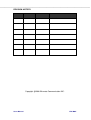
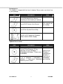
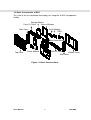
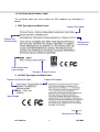
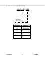
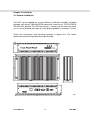
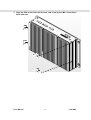
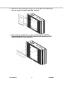
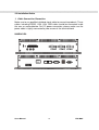
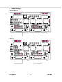
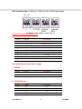
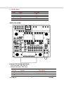
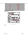
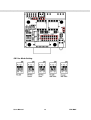
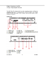
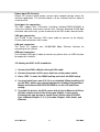
Embedded Automation
Controller BOX
USER MANUAL
Version: 1.4
I330EAC-ID3
Users Manual
Intel NM10 / Atom N2800 with 3 Isolated
Serial Port Controller
EAC BOX
REVISION HISTORY
REVISION
1.4
AUTHOR
Jovi Hsu
DATE
March 7,2013
DESCRIPTION
I330EAC-ID3
Copyright @2008 Winmate Communication INC.
Users Manual
EAC BOX
IMPORTANT SAFETY INSTRUCTIONS
Please read these instructions carefully before using the product and save for
later reference.
Follow all warnings and instructions marked on the product.
Unplug this product from the wall outlet before cleaning. Clean the product with
a damp soft cloth. Do not use liquid or aerosol cleaners as it may cause
permanent damage to the screen.
Do not use this product near water.
Do not place this product on an unstable cart, stand, or table. The product may
fall, causing serious damage to the product.
This product should be operated from the type of power indicated on the
marking label. If you are not sure of the type of power available, consult your
dealer or local power company.
This product is equipped with a 3-wire grounding type plug, a plug having a
third (grounding) pin. This plug will only fit into a grounding-type power outlet.
This is a safety feature. If you are unable to insert the plug into the outlet,
contact your electrician to replace your obsolete outlet. (For AC version only)
Do not defeat the purpose of the grounding-type plug.
Do not allow anything to rest on the power cord.
where persons will walk on the cord.
Do not locate this product
Never push objects of any kind into this product through cabinet slots as they
may touch dangerous voltage points or short out parts that could result in a risk
of fire or electric shock. Never spill liquid of any kind on the product.
Do not attempt to service this product by yourself, as opening or removing
covers may expose you to dangerous voltage points or other risks and will void
the warranty. Refer all servicing to qualified service personnel.
Unplug this product from the wall outlet and refer servicing to qualified service
personnel under the following conditions:
When the power cord or plug is damaged or frayed.
If liquid has been spilled into the product.
If rainy or water has been exposed to the product.
If the product does not operate normally that the operating instructions are
followed. Adjust only those controls that are covered by the operating
instructions since improper adjustment of other controls may result in damage
and will often require extensive work by a qualified technician to restore the
product to normal operation.
If the product has been dropped or the cabinet has been damaged.
If the product exhibited a distinct change in the performance, that indicates a
need for service.
Users Manual
2
EAC BOX
Packaging List
This product is shipped with the items list below. Please make sure that all are
in your package.
Item
Description
Note
1 pc of Mainboard User Manual
according to what model you ordered.
1 pc of EAC System User Manual.
This manual you
are reading.
1 pc CD for System Driver Utility.
1 pc AC to DC Adapter w/ Standard
Power Cord for Power Supply.
Optional Accessories
Item
Description
Note
1 pc of CD for Recovery CD for
Operation System (Windows 7
Embedded or Windows 7 Professional
Embedded).
Optional with
Windows 7
embedded or
Windows 7
Professional
1 pc of Windows 7 embedded or Embedded
Windows 7 Professional Embedded pre-installed.
Recovery Users Guide.
Users Manual
3
EAC BOX
Contents
IMPORTANT SAFETY INSTRUCTIONS .........................................................2
CHAPTER 1 GENERAL INFORMATION ........................................................6
1.1 FEATURES ABOUT THE EMBEDDED AUTOMATION CONTROLLER ..6
1.2 BASIC CONSTRUCTION OF EAC ...........................................................8
1.3 CERTIFICATE SERIAL NUMBER LABEL ................................................9
CHAPTER 2 INSTALLATION ........................................................................12
2.1 GENERAL INSTALLATION.....................................................................12
2.2 INSTALLATION NOTICE.........................................................................15
CHAPTER 3 OPERATION OF THE EAC ......................................................22
3.1 INPUT / OUTPUT SIGNALS OVERVIEW ...............................................22
3.2 STARTING THE EAC & O/S INSTALLATION.........................................23
Users Manual
4
EAC BOX
CHAPTER 1
General Information
Users Manual
5
EAC BOX
Chapter 1 General Information
The EAC (Embedded Automation Controller) is high performance, fanless, low
power consuming computer. The EAC is designed with wide temperature
ranged, Anti-shock, Anti-vibration, isolated RS232/422/485 serial ports, wide
voltage range power input acceptable, and anti-corrosion protection. The EAC
is born to the demands of maritime applications as navigation, ship automation,
surveillance, rugged industry and light military applications.
All product designs follow IEC-60945 Maritime Navigation and Radiocommunication Equipment and Systems requirements.
1.1 Features about the Embedded Automation Controller
Here are features of Embedded Automation Controllers:
Fanless, Low Power CPU with Versatile Functions
The EAC with Intel Atom N2800 / NM10 Chipset that delivers the most
performance per watt available in embedded computing systems. It’s a
PC-based system with DDR3 RAM, VGA controller, multi-COM port interface,
and on-board 10/100/1000 Mbps Ethernet, USB port. It is a compact design to
meet the demanding performance requirements of most applications.
Wide Voltage Input Range and Isolated Power Input
For marine and transportation power source characteristic, our displays use
wide voltage range from 9 to 36V input acceptable with isolation resistance at
1.5KV DC. 12V and 24V DC input are also available.
55
-15
C
°
Wide Range Operating Temperature
With excellent design on heat dissipation, the EAC could bear more critical
environment condition in temperature. This range is from 55°C to -15°C. Based
on this feature, the EAC could meet most of the requirement of marine time
applications.
Users Manual
6
EAC BOX
Anti-Shock and Vibration
With anti-vibration and shock mechanical design makes our EAC solution
enhanced shock and vibration resistance.
GPIO Phoenix Type Connector
The EAC reserved GPIO for general purpose control use of Input or output
needs. And the phoenix type connector is easy to plug in with wide range pitch
of wires.
Isolated Serial Ports with RS232//422//485
For mostly used connection of peripheral devices, the EAC provides rich serial
ports for NEMA compliance device, like GPS, ARPA, Gyro…etc. And for
protecting these devices from been surge voltage, isolated serial ports provide
2.5K DC protection by Auto-isolator technology to protect expensive devices.
Customize your products
Base on our well-experience modulated competence, we can do very flexible
and tailor-made design fulfilling any of customer’s solution. For different panel
characteristics, mechanical design, and electronic component, we can make it
for you.
Approved EAC
Winmate EAC designs are all followed IEC-60945 Maritime Navigation and
Radio- communication Equipment and Systems requirements.
The EAC series consist in different platform of industrial computing. By testing
for usability in a ship’s wheelhouse during different ambient conditions. All
these models can fulfill most of the demands in maritime applications
especially for navigation, ship automation and maritime surveillance.
About this Manual
The users’ manual introduces basic information about the product, electrical,
mechanical and input / output signal specifications. All specifications are
subject to change without prior notice due to manufacturing reasons. Check in
the “Revision History” in front page of this manual for any update reference.
Users Manual
7
EAC BOX
1.2 Basic Construction of EAC
The state of the art modulated technology can integrate all EAC components
flexibly.
Storage Module
Front I/O Cover
Service Window
Serial Module
GPIO
Side Cover
Main Board Module
Top Cover
Power Module
Back I/O Cover
Bottom Cover
Side Cover
Figure 1.1 Basic Constructions
Users Manual
8
EAC BOX
1.3 Certificate Serial Number Label
The certificate label and serial number for EAC products are described as
below.
1. DNV Type Approval Model Label:
Product and
Serial Number
Power Rating and
Input Voltage
Product Description
Manufacturer
and Country
Compass Safety Distance
2. No DNV Type Approval Model Label
Product and Serial Number
Product Description
Input Voltage
Manufacturer Country
Users Manual
9
EAC BOX
3. Model Serial Number (For EAC Box PC)
I330 EAC – XXX
Product
Category
Serial
Number
SBC Board
Platform
Serial Number
Users Manual
Description
201
Std Package
202
w/ display extension
203
w/ PCI extension
204
w/ USB extension
205
w/ COM extension
206
w/ Fan extension
ID3
w/ NM10 chipset
IV3
w/ HM76 chipset
10
EAC BOX
CHAPTER 2
Installation
Users Manual
11
EAC BOX
Chapter 2 Installation
2.1 General installation
The EAC can be applied for several different installation methods, Including
desktop, wall mount, 100x100 VESA mount with screws only; 75x75 VEAS or
DIN Rail with bracket. For DIN Rail mount is normally for the industrial fields
use, it’s easy to follow few steps to fix the display product in customer’s fixture.
Check the mechanical and mounting concept as below first. The fixture
dimension and mounting holes based on drawing.
mm
Users Manual
12
EAC BOX
1. Align the EAC to the fixture on the back, and screw by four M4 x 8 mm above
bolts with nuts.
Users Manual
13
EAC BOX
2. VESA mount with mounting kit using screw by four M4 x 8 mm above bolts
with nuts by special request. (Non-DNV approved)
3. (Optional) Use two M4x 8mm bolts to drill through the DIN Rail
mounting bracket into the mounting holes on the rear side of EAC
100x100 VEAS. (Non-DNV approved)
Users Manual
14
EAC BOX
2.2 Installation Notice
1. Cable Connection Precaution
Make sure to use qualified shielded signal cable to connect to products. These
cables including RS232, VGA, LAN, USB cable should be connected inside
the area as marked below. For DC power connection, please make sure the
power cable is tightly connected by two screws of the terminal block.
I330EAC-ID3
COM2
Users Manual
15
COM3 COM4
EAC BOX
2. Jumper Settings
1.RS-485/RS-422
RS2T4-420
2.RS-232
RS2T4-420
Users Manual
16
EAC BOX
SW1 (On Back side): COM3(J3) / COM4(J8) RS-422/485 Mode Switch
J8 RS485 / 422 setting is same with J3
D-Sub 9P RS-232/RS-422/RS-485 (J3,J8)
Used connector: DB9 Female
Related connector: DB9 Male
Pin No.
1
Symbol
P1
Description
DCD/D-/TX-/RX-
2
P2
RXD/D+/TX+/RX+
3
P3
TXD/RX+/TX+
4
P4
DTR/RX-/TX-
5
GND
Ground
6
P6
DSR/NC
7
P7
RTS/NC
8
P8
CTS/NC
9
P9
RI/NC
Pins definition of J3 and J8 of 3 types
1. RS-485
Pin No.
1
Symbol
P1
Description
D-
2
P2
D+
2. RS-422 Master
Pin No.
1
Symbol
P1
Description
TX-
2
P2
TX+
3
P3
RX+
4
P4
RX-
Users Manual
17
EAC BOX
3. RS-422 Slave
Pin No.
1
Symbol
P1
Description
RX-
2
P2
RX+
3
P3
TX+
4
P4
TX-
RS2T4-330 (COM2)
D-Sub 9P RS-232/RS-422/RS-485
Used connector: DB9 Female
Related connector: DB9 Male
Pin No.
1
Symbol
P1
Description
DCD/D-/TX-/RX-
2
P2
RXD/D+/TX+/RX+
Users Manual
18
EAC BOX
3
P3
TXD/RX+/TX+
4
P4
DTR/RX-/TX-
5
GND
Ground
6
P6
DSR/NC
7
P7
RTS/NC
8
P8
CTS/NC
9
P9
RI/NC
Jumpers for Mode Setting (COM2)
RS-485/RS-422
RS-232
Users Manual
19
EAC BOX
SW1 for Mode Setting
Users Manual
20
EAC BOX
CHAPTER 3
Operation the EAC
Users Manual
21
EAC BOX
Chapter 3 Operation of the EAC
3.1 Input / Output Signals Overview
The EAC Box PCs designed with versatile computing functions fulfilling the
embedded applications. The default function include COM ports (with isolated
RS232/422/485), VGA output, USB 2.0, power input connector, power switch,
audio jack, and GPIO
I330EAC-ID3
COM2
Users Manual
22
COM3
COM4
EAC BOX
Power input (DC Version)
Default DC terminal block power source input compact design meets the
maritime application. The terminal block is to be secured that the cable to
screw terminal.
Serial ports for connection
The EAC support Rich COM ports (including isolated RS232/422/485) to
satisfy the maritime accessories sensor units. Connect Standard D-SUB 9pin
connector from accessory system to connect to the EAC to be a control center.
VGA port connection
Use D-SUB 15-pin (Female) VGA signal cable to connect to the display.
Fasten cable connectors with screws.
LAN port connection
The Panel PC supports one 10/100/1000 Mbps Ethernet interface for
connecting to the internet.
USB port connection
Use standard USB type A cable to connect any device that use USB interface
for expansion functions.
3.2 Starting the EAC & O/S Installation
1. Connect the EAC to Monitor through VGA cable.
2. Connect the power to DC source and turn on the power switch.
3. Press “DEL” to enter the CMOS setting and check the BIOS setup.
4. You may install your own O/S if it is not installed. When installing O/S
for this EAC, please use external equipment including Keyboard and
Mouse and external USB CD/DVD-ROM to run the O/S and Driver
setting.
5. To install the drivers, the EAC comes with a User’s Manual and Driver
CD that contains most of the drivers and utilities of your needs.
Following the step by step to install Driver (Please refer ID32 SBC
User’s Manual Chapter 3, 4, 5, 6) include: Chipset, VGA, Audio, and
Ethernet.
Users Manual
23
EAC BOX