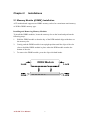
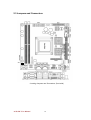
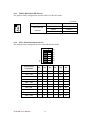
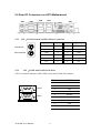
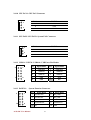
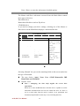
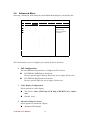
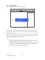
1
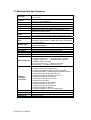
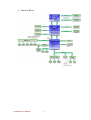
A270 SBC Mini-ITX SBC w/ Socket AM2 AMD Athlon 64 X2 / Athlon 64 35W and 65W CPU, VGA, DVI, LCD, Ethernet and Mini-PCI Interface. USER MANUAL Version 1.1 FCC Statement This device complies with part 15 FCC rules. Operation is subject to the following two conditions: This device may not cause harmful interference. This device must accept any interference received including interference that may cause undesired operation. This equipment has been tested and found to comply with the limits for a class "a" digital device, pursuant to part 15 of the FCC rules. These limits are designed to provide reasonable protection against harmful interference when the equipment is operated in a commercial environment. This equipment generates, uses, and can radiate radio frequency energy and, if not installed and used in accordance with the instruction manual, may cause harmful interference to radio communications. Operation of this equipment in a residential area is likely to cause harmful interference in which case the user will be required to correct the interference at him own expense. z z A270 SBC User Manual I Copyright Notice Copyright © 2007 Winmate Technology Inc., ALL RIGHTS RESERVED. No part of this document may be reproduced, copied, translated, or transmitted in any form or by any means, electronic or mechanical, for any purpose, without the prior written permission of the original manufacturer. Trademark Acknowledgement Brand and product names are trademarks or registered trademarks of their respective owners. Disclaimer Winmate Communication Inc. reserves the right to make changes, without notice, to any product, including circuits and/or software described or contained in this manual in order to improve design and/or performance. Winmate Communication assumes no responsibility or liability for the use of the described product(s), conveys no license or title under any patent, copyright, or masks work rights to these products, and makes no representations or warranties that these products are free from patent, copyright, or mask work right infringement, unless otherwise specified. Applications that are described in this manual are for illustration purposes only. Winmate Communication Inc. makes no representation or warranty that such application will be suitable for the specified use without further testing or modification. Warranty Winmate warrants that each of its products will be free from material and workmanship defects for a period of one year from the invoice date. If the customer discovers a defect, Winmate will, at its option, repair or replace the defective product at no charge to the customer, provided it is returned during the warranty period of one year, with transportation charges prepaid. The returned product must be properly packaged in it’s original packaging to obtain warranty service. If the serial number and the product shipping data differ by over 30 days, the in-warranty service will be made according to the shipping date. In the serial numbers the third and fourth two digits give the year of manufacture, and the fifth digit means the month (e. g., with A for October, B for November and C for December). For example, the serial number 1W07Axxxxxxxx means October of year 2007. A270 SBC User Manual II Packing List Before using this Motherboard, please make sure that all the items listed below are present in your package: ¾ 1 x A270 Motherboard ¾ 1 x A270 SBC User Manual ¾ 1 x A270 SBC User’s Manual & Driver CD ¾ 1 x A270 CPU Sink ¾ 1 x A270 CPU Holder ¾ 1 x 44pin HDD IDE Cable ¾ 1 x HDD SATA Cable ¾ 1 x RS-232 Cable ¾ 1 x USB Cable If any of these items are missing or damaged, contact your distributor or sales representative immediately. Customer Service We provide service guide for any problem as follow steps:First, visit the website at http://www.winmate.com to find the update information about the product. Second, contact with your distributor, sales representative, or our customer service center for technical support if you need additional assistance. You may have the following information ready before you call: ¾ Product serial number ¾ Peripheral attachments ¾ Software (OS, version, application software, etc.) ¾ Description of complete problem ¾ The exact wording of any error messages In addition, free technical support is available from our engineers every business day. We are always ready to give advice on application requirements or specific information on the installation and operation of any of our products. Please do not hesitate to call or e-mail us. Warranty Winmate warrants that each of its products will be free from material and workmanship defects for a period of one year from the invoice date. If the customer discovers a defect, Winmate will, at its option, repair or replace the defective product at no charge to the customer, provided it is returned during the warranty period of one year, with transportation charges prepaid. The returned product must be properly packaged in it’s original packaging to obtain warranty service. If the serial number and the product shipping data differ by over 30 days, the in-warranty service will be made according to the shipping date. In the serial numbers the third and fourth two digits give the year of manufacture, and the fifth digit means the month (e. g., with A for October, B for November and C for December). For example, the serial number 1W07Axxxxxxxx means October of year 2007. A270 SBC User Manual III Safety Precautions Warning! Always completely disconnect the power cord from your chassis whenever you work with the hardware. Do not make connections while the power is on. Sensitive electronic components can be damaged by sudden power surges. Only experienced electronics personnel should open the PC chassis. Caution! Always ground yourself to remove any static charge before touching the CPU card. Modern electronic devices are very sensitive to static electric charges. As a safety precaution, use a grounding wrist strap at all times. Place all electronic components in a static-dissipative surface or static-shielded bag when they are not in the chassis. A270 SBC User Manual IV Safety and Warranty 1. 2. 3. Please read these safety instructions carefully. Please keep this user's manual for later reference. Please disconnect this equipment from any AC outlet before cleaning. Do not use liquid or spray detergents for cleaning. Use a damp cloth. 4. For pluggable equipment, the power outlet must be installed near the equipment and must be easily accessible. 5. Keep this equipment away from humidity. 6. Put this equipment on a reliable surface during installation. Dropping it or letting it fall could cause damage. 7. The openings on the enclosure are for air convection. Protect the equipment from overheating. DO NOT COVER THE OPENINGS. 8. Make sure the voltage of the power source is correct before connecting the equipment to the power outlet. 9. Position the power cord so that people cannot step on it. Do not place anything over the power cord. 10. All cautions and warnings on the equipment should be noted. 11. If the equipment is not used for a long time, disconnect it from the power source to avoid damage by transient over-voltage. 12. Never pour any liquid into an opening. This could cause fire or electrical shock. 13. Never open the equipment. For safety reasons, only qualified service personnel should open the equipment. 14. If any of the following situations arises, get the equipment checked by service personnel: A. The power cord or plug is damaged. B. Liquid has penetrated into the equipment. C. The equipment has been exposed to moisture. D. The equipment does not work well, or you cannot get it to work according to the user’s manual. E. The equipment has been dropped and damaged. F. The equipment has obvious signs of breakage. 15. Do not leave this equipment in an uncontrolled environment where the storage temperature is below -20° C (-4°F) or above 60° C (140° F). It may damage the equipment. A270 SBC User Manual V Revision History Version Date Note Author 0.1 2007.05.16 9 First Version Tin Lai 0.2 2007.06.11 9 Increase Driver installation Tin Lai 0.3 2007.06.25 9 Update SW1 Pin definition for Panel 9 Revise BIOS Item Tin Lai solution Selector 9 Revise BIOS Item 9 Increase Chapter 2.5.7 Multiple Display Function 9 Increase Chapter 7 Cool n’ Quiet Driver Installation 1.0 2007.07.15 1.1 2007.10.15 9 Change Com1 and Com2 Aladin 2007.10.30 9 Add 1920x1080, 1920x1200 Aladin A270 SBC User Manual VI Tin Lai A270 SBC User Manual VII Contents CHAPTER 1 GENERAL INFORMATION.................................................................................... 2 1.1 INTRODUCTION....................................................................................................................... 2 1.2 FEATURE ................................................................................................................................ 2 1.3 MOTHERBOARD SPECIFICATIONS ........................................................................................... 3 1.4 BOARD DIMENSIONS ............................................................................................................... 5 CHAPTER 2 INSTALLATIONS ..................................................................................................... 7 2.1 MEMORY MODULE(DIMM)INSTALLATION ....................................................................... 7 2.2 I/O EQUIPMENT INSTALLATION .............................................................................................. 8 2.3 JUMPERS AND CONNECTORS................................................................................................. 10 2.4 JUMPER SETTING .................................................................................................................. 11 2.5 REAR I/O CONNECTORS ON A270 MOTHERBOARD .............................................................. 13 2.6 CONNECTORS AND PIN ASSIGNMENT.................................................................................... 16 CHAPTER 3 PHOENIX BIOS SETUP ........................................................................................ 24 3.1 STARTING SETUP .................................................................................................................. 24 3.2 PHOENIX BIOS SETUP .......................................................................................................... 26 3.3 MAIN MENU ......................................................................................................................... 27 3.4 ADVANCED MENU ................................................................................................................ 33 3.5 SECURITY MENU .................................................................................................................. 36 3.6 POWER MENU ...................................................................................................................... 38 3.7 BOOT MENU ......................................................................................................................... 39 3.8 EXIT MENU .......................................................................................................................... 41 CHAPTER 4 4.1 CHIPSET DRIVER INSTALLATION .................................................................. 45 STANDARD CMOS FEATURES .............................................................................................. 45 CHAPTER 5 ETHERNET DRIVER INSTALLATION .............................................................. 49 5.1 INTRODUCTION..................................................................................................................... 49 5.2 INSTALLATION OF ETHERNET DRIVER .................................................................................. 50 CHAPTER 6 AUDIO DRIVER INSTALLATION....................................................................... 53 6.1 INTRODUCTION..................................................................................................................... 53 6.2 INSTALLATION OF AUDIO DRIVER......................................................................................... 53 CHAPTER 7 AMD COOL N’ QUIET DRIVER INSTALLATION ........................................... 56 7.1 INTRODUCTION..................................................................................................................... 56 7.2 INSTALLATION OF AMD COOL N’ QUIET DRIVER ................................................................. 57 A270 SBC User Manual VIII CHAPTER General Information 1 This chapter includes A270 Motherboard background information. Sections include: z Introduction z Feature z Motherboard Specification z Function Block z Board Dimensions A270 SBC User Manual 1 Chapter 1 General Information 1.1 Introduction A270 Mini ITX board incorporates the AMD M690G Chipset for Embedded Computing, consisting of the two core components: AMD M690G and SB600 Chipset, an optimized integrated graphics solution with a 1000MHz HyperTransport Technology. Dimensions of the board are 170mm x 170mm. AMD M690G Chipset integrated powerful 3D graphics engine, based on ATI Radeon X700-based Graphics architecture. It features a low-power design, is validated with the AMD® Athlon™ 64 and AMD® Athlon™ 64 X2 35W and 65W processors on 90nm process. With dual channel DDR2 533/667/800 MHz two DIMM socket on board, up to 4GB of DDR2 system memory. AMD SB600 Chipset provides leading performance and the most universal connectivity options today. Eliminating the need for a USB hub, the SB600 provides up to 10 USB 2.0 ports. Connect with all types of peripherals with full compliancy to PCI and LPC bus support for all legacy devices. Complete the multimedia experience with high-definition audio and support for HD DVD and Blu-Ray HD audio. 1.2 Feature ¾ ¾ ¾ ¾ ¾ ¾ ¾ ¾ ¾ ¾ Designed for Mini-ITX Motherboard Socket AM2 supports AMD Athlon 64 / Athlon 64 X2 35W processor, up to 1.8GHz Socket AM2 supports AMD Athlon 64 / Athlon 64 X2 65W processor, up to 2.6GHz System memory up to 4GB DDR2 533/667/800 SDRAM Integrated AMD M690G + SB600 Chipset Integrated VGA / LVDS / DVI, ATI Graphic Integrate X700-based Dual Gigabit LAN High Performance and Anti-Vibration to ensure maximum reliability 2 x SATAI/II, 10 x USB 2.0, 4 x COM, 2 x RJ-45, 1 x Mini PCI, 1 x PCI, 1 x VGA, 1 x DVI A270 SBC User Manual 2 1.3 Motherboard Specifications CPU Type CPU HT CPU Socket Chipset BIOS Cache VGA LVDS DVI LAN Memory Type LPC I/O Keyboard/Mouse IDE Interface Sound USB Edge Connectors On Board Pin-Header Connectors Power Connector Expansion Slots Form Factor Dimensions A270 SBC User Manual AMD®Athlon™ 64 X2 / Athlon™ 64 35W or 65W processors, up to 2.6GHz HyperTransport™ interface speed is depended on AMD processors, up to 2000MHz Socket AM2 AMD M690G / SB600 chipset Phoenix 8Mbit BIOS 1MB AMD M690G built-in ATI Radeon X700-based Graphics 256MB shared with system AMD M690G built-in, single- or dual-channel panel support up to WUXGA panel resolution. Max. to 1920x1200, 24bit DVI out 2 x Gigabit Ethernet ( Dual Realtek RTL8111B Gigabit LAN COntroller, Optional Dual Realtek RTL8101E 10/100Base -T LAN Controller ) 2 x DDR2 DIMM socket, supports up to 4GB DDR 533/667/800 SDRAM ITE 8712 2 x PS/2 Keyboard/Mouse connectors One channels; supports Ultra DMA 33/66/100 Realtek ALC655 5.1 channel (Line-out, Line-in & Mic in) 10 ports, USB 2.0 ( 4 x USB Conn., 6 x USB pin-header ) 2 x PS/2 connector for keyboard/mouse 1 x Gigabit LAN RJ-45 + 1 x dual USB stack connector 1 x Gigabit LAN RJ-45 + 1 x dual USB stack connector 2 x DB9 for COM 1 & COM 2 1 x VGA out connector + 1 x DVI out connector 1 x Audio Jack for Audio (Line-Out, Line-In) 1 x 44 pins box-header 2 x SATA connector for SATAI/II ports, 2 x 10pins pin-header for COM 3 & COM 4 (RS232) 2 x 3pins pin-header for COM4 selection (RS232/422/485) 1 x 5pins pin-header for RS-422/485 insert 2 x 5pins pin-header for USB 5/6, 7/8, 9/10 x 3 2 x 6pins pin-header for Front Audio 1 x 40pins DF13 Connector for LVDS 1 x 20pins ATX connector. 2 x 5pins pin-header for Front Panel 1 x 3pins pin-header for CPU Fan 1 x 3pins pin-header for System Fan 1 x 3pins pin-header for NB Fan 1 x 2pins pin-header for 5V, 12V Voltage input Input: 20-pin ATX Power input 1 x PCI, 1 x Mini-PCI Mini-ITX 170mm x 170mm 3 ¾ Function Block 65W/ A270 SBC User Manual 4 1.4 Board dimensions A270 SBC User Manual 5 CHAPTER Installations 2 This chapter provides information on how to use the jumps and connectors on A270 Motherboard. The Sections include: z Memory Module Installation z I / O Equipment Installation z Setting the Jumpers z Connectors on A270 Motherboard A270 SBC User Manual 6 Chapter 2 Installations 2.1 Memory Module(DIMM)Installation A270 motherboard supports two DDR2 memory socket for a maximum total memory of 4GB in DDR2 memory type. Installing and Removing Memory Modules To install the DDR2 modules, locate the memory slot on the board and perform the following steps: 1. Hold the DDR2 module so that the key of the DDR module align with those on the memory slot. 2. Gently push the DDR2 module in an upright position until the clips of the slot close to hold the DDR2 module in place when the DDR module touches the bottom of the slot. 3. To remove the DDR2 module, press the clips with both hands. Lock DDR2 Module Lock A270 SBC User Manual Lock Lock 7 2.2 I/O Equipment Installation 2.5.1 Audio function The Audio 5.1 channel capabilities are provided by a Realtek ALC655 chipset supporting digital audio outputs. The audio interface includes two jacks: line-in and line-out. 2.5.2 Serial COM ports Two RS-232 connectors build in the rear I/O. One optional COM ports support RS-232. When an optional touch-screen is ordered with PPC, serial com port can connect to a serial or an optional touch-screen. One optional COM port supports RS232/422/485 choice through jumper setting. 2.5.3 Ethernet interface The Motherboard is equipped with Dual Realtek RTL8111B (Optional Dual Realtek RTL8101E) chipset which is fully compliant with the PCI 10/100/1000 Mbps Ethernet protocol compatible. It is supported by major network operating systems. The Ethernet ports provide the standard RJ-45 jack. 2.5.4 USB ports Ten USB device may be connected to the system though an adapter cable. Various adapters may come with USB ports. USB usually connect the external system to the system. The USB ports support hot plug-in connection. Whatever, you should install the device driver before you use the device. 2.5.5 External VGA The Motherboard has one VGA port that can be connected to an external CRT/ LCD monitor. Use VGA cable to connect to an external CRT / LCD monitor, and connect the power cable to the outlet. The VGA connector is a standard 15-pin D-SUB connector. 2.5.6 External DVI The Motherboard has one DVI port that can be connected to an external DVI/ LCD monitor. Use DVI cable to connect to an external DVI / LCD monitor, and connect the power cable to the outlet. The DVI connector is a standard DVI-D connector. 2.5.7 Multiple Display Function A270 SBC integrated AMD M690G chipset, and provided VGA / LVDS / DVI outputs. The Mutli-display application is available for A270 SBC. Customers can A270 SBC User Manual 8 select two display devices of the VGA / DVI / LVDS output interface display. Then these displays can be set as desktop or extended desktop display via ATI Graphic utility. Possible configurations include: 9 LCD and CRT 9 LCD and DVI 9 CRT and DVI A270 SBC User Manual 9 2.3 Jumpers and Connectors SW1 Locating Jumpers and Connectors (front side) A270 SBC User Manual 10 2.4 Jumper Setting A270 has a number of jumpers that allow you to configure your system to suit your application. The table below lists the functions of the various jumpers. The following tables list the function of each of the board's jumpers. Label Function Note JP1 Clear CMOS 3x1 header, pitch 2.0mm JP2 Brightness control VR 3x1 header, pitch 2.0mm JP602 RS232/422/485 Selector 3x4 header ,pitch 2.0mm SW1 Panel Solution Selector 6 x 2 Jumper 2.4.1 JP1: Clear CMOS User must make sure the power supply to turn off the power supply before setting Clear CMOS. Users remember to setting jumper back to Normal before turning on the power supply. * : default Description 1 2 3 Function Pin# Clear CMOS 1 Short 2 Normal * 2 Short 3 Pin# Function 1 VCC (5V) 2 Control Pin 3 Gnd Power on Mode 2.4.2 JP2: Brightness control VR JP2 is Brightness control VR 1 Description 2 3 Brightness control VR A270 SBC User Manual 11 2.4.3 JP602: RS232/422/485 Selector The jumper can be configured to operate in RS-232/422/485 mode. * : default Description 1 2 3 4 RS232/422/485 5 6 Selection Function Pin# RS232* 1 Short 2 RS422 3 Short 4 RS485 5 Short 6 2.4.4 SW1: Panel Resolution Selector The Switch can be configured to select Panel Resolution mode. NO 0 6 1 ID5 0 5 1 ID4 0 4 1 ID3 0 3 1 ID2 0 2 1 ID1 0 1 1 ID0 Panel Resolution ID0 ID1 ID2 ID3 ID4 ID5 Default 0 0 0 0 NC NC 1024 x 768 1 0 0 0 NC NC 1280 x 1024 0 1 0 0 NC NC 1600 x 1200 1 1 0 0 NC NC 1680 x 1050 0 0 1 0 NC NC 640 x 480 1 0 1 0 NC NC 800 x 600 0 1 1 0 NC NC 1366 x 768 1 1 1 0 NC NC 1920 x 1080 0 0 0 1 NC NC 1920 x 1200 1 0 0 1 NC NC For A270 SBC A270 SBC User Manual 12 2.5 Rear I/O Connectors on A270 Motherboard CN1 CN2 CN3 CN4 CN7 CN5 CN6 2.5.1 CN1:PS/2 Keyboard and PS/2 Mouse Connectors PS/2 Mouse Signal Name Keyboard Mouse Signal Name Keyboard data 1 1 Mouse data N.C. 2 2 N.C. GND 3 3 GND 5V 4 4 5V Keyboard clock 5 5 Mouse clock N.C. 6 6 N.C. PS/2 Keyboard 2.5.2 CN2:COM1 and COM2 serial Ports CN2 is a stacked connector with COM2 on top and COM1 at the bottom. 1 2 3 4 5 6 7 8 9 1 2 3 4 5 6 7 8 9 A270 SBC User Manual COM 2 COM 1 13 Pin No. SYMBOL 1 DCD 2 RxD 3 TxD 4 DTR 5 Ground 6 DSR 7 RTX 8 CTS 9 RI 2.5.3 CN3: RJ45 and 2 USB Ports CN3 is a stacked connector with RJ45 on top and 2 USB Port at the bottom. 2.5.4 CN4: RJ45 and 2 USB Ports CN4 is a stacked connector with RJ45 on top and 2 USB Port at the bottom 2.5.5 CN5: VGA Connector Pin No. A270 SBC User Manual SYMBOL 1 RED 2 GREEN 3 BLUE 4 NA 5 GND 6 GND 7 GND 8 GND 9 LVGA5V 10 GND 11 NA 12 DAC_SDAT 13 HSYNC# 14 VSYNC# 15 DAC_SCL 14 2.5.6 CN6: DVI Connector Pin # Signal Name Pin # Signal Name Pin # Signal Name 1 TMDS Data2- 9 TMDS Data1- 17 TMDS Data0- 2 TMDS Data2+ 10 TMDS Data1+ 18 TMDSData0+ 3 TMDS Data2/4 Shield 11 TMDS Data1/3 Shield 19 TMDS Data0/5 Shield 4 TMDS Data4- 12 TMDS Data3- 20 TMDS Data5- 5 TMDS Data4+ 13 TMDS Data3+ 21 TMDS Data5+ 6 DDC Clock [SCL] 14 +5 V Power 22 TMDS Clock Shield 7 DDC Data [SDA] 15 Ground (for +5 V) 23 TMDS Clock + 8 Analog vertical sync 16 Hot Plug Detect 24 TMDS Clock - C1 N/A C3 N/A C2 N/A C4 N/A C5 N/A 2.5.7 CN7: Audio Connector The audio connector, from top to bottom, is composed of Line in and Line out. A270 SBC User Manual 15 2.6 Connectors and Pin Assignment The table below lists the function of each of the board’s connectors. Label Function Note CON3 LVDS LCD Output Connector DF13-40DP-1.25V CON4 CON5 Control Digital Panel Power On / Off Digital Panel Backlight Brightness Control 3x2 header, pitch 2.54mm 7x1 header, pitch 2.0 mm CON6 RS-422 / RS-485 Header 5x1 header, pitch 2.0 mm CON7 VCC(+5V) 2x1 header, pitch 2.0 mm CON8 VCC(+12V) 2x1 header, pitch 2.0 mm COM3/COM4 RS-232 Series Port 2x10 header, pitch 2.0mm IDE1 Primary IDE Connector 2x22 pin IDE Conn. ATX1 ATX Power Connector 20 pin ATX Power Conn. CPU FAN1 CPU FAN Conn. 3x1 header, pitch 2.54mm SYS FAN1 System FAN Conn. 3x1 header, pitch 2.54mm SYS FAN2 System FAN Conn. 3x1 header, pitch 2.54mm USB5.6 USB Ports 5x2 header, pitch 2.0 mm USB7.8 USB Ports 5x2 header, pitch 2.0 mm USB9.10 USB Ports 5x2 header, pitch 2.0 mm PANEL 1 System Function Connector 5x2 header ,pitch 2.0mm Audio 2 Audio Function Connector 6x2 header ,pitch 2.0mm A270 SBC User Manual 16 2.6.1 CON3: LVDS LCD Output Connector 40 2 1 1 39 Pin No. SYMBOL Pin No. SYMBOL 1 LCDVDD 21 GND 2 LVDS_TXL0N 22 LVDS_TXU0N 3 LCDVDD 23 GND 4 LVDS_TXL0P 24 LVDS_TXU0P 5 LCDVDD 25 GND 6 LVDS_TXL1N 26 LVDS_TXU1N 7 GND 27 GND 8 LVDS_TXL1P 28 LVDS_TXU1P 9 GND 29 GND 10 LVDS_TXL2N 30 LVDS_TXU2N 11 GND 31 GND 12 LVDS_TXL2P 32 LVDS_TXU2P 13 GND 33 GND 14 LVDS_TXLCKN 34 LVDS_TXUCKN 15 GND 35 GND 16 LVDS_TXLCKP 36 LVDS_TXUCKP 17 GND 37 GND 18 LVDS_TXL3N 38 LVDS_TXU3N 19 GND 39 GND 20 LVDS_TXL3P 40 LVDS_TXU3P A270 SBC User Manual 17 2.6.2 CON4: Control Digital Panel Power On / Off * : default Description 1 2 3 4 Control Digital Panel 5 6 Power On / Off Function Pn# VCC3(3.3V)* 1 Short 2 VCC( 5V) 3 Short 4 +12V 5 Short 6 2.6.3 CON5: Digital Panel Backlight Brightness Control 1 1 2 3 4 5 6 7 7 Pin No. 1 2 3 4 5 6 7 SYMBOL +12V +12V +12V Gnd Control Pin Gnd BLON( TO NB) 2.6.4 CON6: RS-422 / RS-485 Header 1 422 RX2- Pin No. 2 422 RX2+ 3 485TXRX2- 4 485TXRX2+ 5 Gnd 1 2 3 4 5 A270 SBC User Manual SYMBOL 422 RX2422 RX2+ 485 TXRX2485TXRX2+ Gnd 18 2.6.5 CON7: VCC(+5V) Pin No. 1 SYMBOL +5V 2 Gnd 1 2 2.6.6 CON8: VCC(+12V) 1 Pin No. 2 1 SYMBOL +12V 2 Gnd 2.6.7 COM3/COM4: RS-232 Series Port F81216D Pin No. SYMBOL Pin No. SYMBOL 20 19 1 FK_NDCD1 11 FK_NDCD2 2 17 2 FK_NDSR1 12 FK_NDSR2 16 15 3 FK_NSIN1 13 FK_NSIN2 14 13 4 FK_NRTS1 14 FK_NRTS2 12 11 10 9 5 FK_NSOUT1 15 FK_NSOUT2 8 7 6 FK_NCTS1 16 FK_NCTS2 6 5 7 FK_NDTR1 17 FK_NDTR2 4 3 8 FK_NRI1 18 FK_NRI2 2 1 9 GND 19 GND 10 GND 20 GND A270 SBC User Manual 19 2.6.8 IDE1: 44Pin IDE Connector Pin No. SYMBOL Pin No. SYMBOL 1 DD7 2 GND 3 DD6 4 DD8 5 DD5 6 DD9 7 DD4 8 DD10 9 DD3 10 DD11 11 DD2 12 DD12 13 DD1 14 DD13 15 DD0 16 DD14 17 DMARQ 18 DD15 19 DIOW- 20 KEY(Removed) 21 DIOR- 22 GND 23 IORDY 24 GND 25 DMACK- 26 GND 27 INTRQ 28 CSEL 29 DA1 30 GND 31 DA0 32 IOCS16- 33 CS1FX- 34 PDIAG- 35 DASP- 36 DA2 37 CS1FX- 38 CS3FX- 39 DASP- 40 GND(Motor) 41 5VDC(Logic) 42 5VDC(Motor) 43 GND(Logic) 44 Reserved 2.6.9 ATX1: ATX Power Connector PIN A270 SBC User Manual SYMBOL PIN SYMBOL 11 3.3V 1 3.3V 12 -12V 2 3.3V 13 Ground 3 Ground 14 PS_ON (Soft on/off) 4 VCC 15 Ground 5 Ground 16 Ground 6 VCC 17 Ground 7 Ground 18 -5V 8 Power Good 19 VCC 9 5V SB (Stand by +5V) 20 VCC 10 +12V 20 2.6.10 CPU FAN1: CPU FAN Connector 1 Pin No. SYMBOL 1 GND 2 +12V 3 SENSE 3 2.6.11 SYS FAN1/ SYS FAN2: System FAN Connector 1 Pin No. SYMBOL 1 GND 2 +12V 3 SENSE 3 2.6.12 USB5.6 / USB7.8 / USB9.10 : USB Ports Pin Header 2 1 10 9 2.6.13 PANEL 1: 2 10 Pin Signal Name Pin Signal Name 1 USBPWR1 2 USBPWR1 3 USBPxN 4 USBPxN 5 USBPxP 6 USBPxP 7 GND 8 GND 9 GND 10 N/C System Function Connector 1 9 A270 SBC User Manual Pin Signal Name Pin Signal Name 1 PW ON LED+ 2 HDD_LED+ 3 PW ON LED- 4 HDD_LED- 5 PW ON Button+ 6 Reset Button- 7 PW ON Button- 8 Reset Button+ 9 N/C 10 5VSB 21 2.6.14 Audio 2: Audio Function Connector 2 12 1 11 A270 SBC User Manual Pin Signal Name Pin Signal Name 2 NC 1 VCC 4 NC 3 GND 6 MIC-R 5 Line-Out R 8 GND 7 GND 10 MIC-L 9 Line-Out L 12 GND 11 GND 22 This chapter describes how to set BIOS configuration A270 SBC User Manual 23 CHAPTER Phoenix BIOS Setup 3 Chapter 3 3.1 Phoenix BIOS SETUP Starting Setup Your computer comes with a hardware configuration program called BIOS Setup that allows you to view and set system parameters. The BIOS (Basic Input / Output System) is a layer of software, called ‘firmware’, that translates instructions from software (such as the operating system) into instructions that the computer hardware can understand. The BIOS settings also identify installed devices and establish special features. ¾ USE BIOS SETUP TO Set the current time and date. Customize your hardware settings according to your needs, Secure your computer with a password. Note: Values for the various setup items that appear on your own screen (including default values) may not be the same as the values shown on the screen figures in this chapter. This is because the BIOS is revised and updated from time to time. If in doubt, check Winmate website for the latest BIOS versions and related information. ¾ ENTERING BIOS SETUP You can access the BIOS program just after you turn on your computer. Just press the F2 key when the following prompt appears: Press <F2> to enter Setup. When you press F2 to enter BIOS Setup, the system interrupts the Power-On Self-Test (POST). If the system detects an error during POST, it prompts you with a double beep and a message: Press <F1> to resume. If you press F1, the system enters the BIOS Setup program. If you want to fix the error, carefully read the error message that appears above the prompt (taking notes if you want) and press F2. Note: If you receive this message repeatedly and the date displayed by your computer is inaccurate, then your CMOS battery may have lost charge. Contact your Technical Support Centre for advice. A270 SBC User Manual 24 ¾ BIOS SETUP SCREENS After you press F2, the system displays the BIOS Setup interface. Use the left and right arrow keys to toggle through the BIOS Setup menu items. ¾ LOOKING AT SCREENS BIOS setup screens have four areas: Menu items - the top of the screen. This area highlights which menu are active. Parameters - the left side of the screen. This area lists parameters and their current settings. Available Options and Help - the right side of the screen. This area lists alternate settings and Help text for each parameter. Key Legend - the bottom of the screen. These lines display the keys that move the cursor and select parameters. Options that are grayed out are not available for the current selection. Settings displayed in blue are automatically detected by your computer. ¾ USING KEYS The following table lists the BIOS Setup keys and their functions: Table 1: BIOS Setup Keys and Associated Functions Key F1 Function Displays a general help screen ← and → Moves between the available menus. ↑ and ↓ Moves the cursor between the displayed parameters. Selects a sub-menu (sub-menus are indicated with a Enter at the beginning of the line), a menu command (such as Exit Discarding Changes), or displays the options available for the currently selected parameter. F5/F6 Steps forward/backward through the settings available for the selected parameter. For some parameter settings, moves the cursor between the subfields. For Tab example, for System Time, Tab moves the cursor from hour to minute to second. Esc Exits any pop-up window and from any menu screen, pressing Escape jumps directly to the Exit menu. F9 Loads the default configurations, as recorded before the computer left the factory. F10 Saves and exits the BIOS setup utility. A270 SBC User Manual 25 3.2 Phoenix BIOS Setup Once you enter the Phoenix BIOS™ CMOS Setup Utility, the Main Menu will appear on the screen. The Setup Utility features five menus which are listed on the menu bar at the top of the screen. The Main Menu allows you to select from several setup functions and two exit choices. User the arrow keys to select among the items and press <← and → > to accept and enter the sub-menu. ¾ Main - use this menu for basic system configuration. ¾ ¾ Advanced - use this menu to set I/0 device configuration and more. Security - use this menu to set user and administrator passwords, and other security features. ¾ ¾ ¾ Power - Use this menu to specify your setting for power management. Boot - use this menu to set the boot sequence. Exit - use this menu to exit the Setup utility with various save or discard options. These menus are described in detail in the following pages. A270 SBC User Manual 26 3.3 Main Menu Use the Main menu screen to view the System Time, System Date and to modify drive parameters and related settings via the HDD Sub-menu. PhoenixBIOS Setup Utility Main Advanced Security Power System Time: [20:27:01] System Date: [01/01/2007] IDE Channel 0 Master [HTS541040G9AT00-(PM)] IDE Channel 0 Slave [None] SATA Port 1 [None] SATA Port 2 [None] Boot Exit Item Specific Help Keyboard Features Boot Features System Memory 633 KB Extended Memory 915456 KB F1 Help ↑ ↓ Select Item Esc Exit ←→ Select Menu -/+ Change Values Enter Select Sub-Menu F9 Setup Defaults F10 Save and Exit The Main Menu allows users to configure system components such as date, time, hard disk drive, floppy drive and display. Use the arrow keys to highlight the item and then use the <Page Up> or <Page Down> keys to select the value you want in each item. The Main Menu screen is shown above. Follow each item: ¾ System Time (hh/mm/ss) Set the time. Enter the current hour, minute and second in hr/min/sec, 24-hour format. To set the time use the Tab or Enter keys to move from field to field. Simply type the new number required. ¾ System Date (mm/dd/yyyy) Set your system's calendar month, day and year. These settings remain in the memory even after you turn off system power. To set the date use the Tab or Enter keys to move from field to field. Simply type the new number required. ¾ IDE Channel1 0 Master / Slave A270 SBC User Manual 27 Press <Enter> to enter the sub-menu to detailed options. The Master and Slave sub-menus accessed from the Main Menu control these types of devices: Hard-disk drives Removable-disk drives such as Zip drives CD-ROM drives If you need to change your drive settings, selecting one of the Master or Slave drives on the Main Menu displays a sub-menu like this: PhoenixBIOS Setup Utility Main Advanced Security Power IDE Channel Master [HTS541040G9AT00-(PM)] Type [Auto] Boot Exit Item Specific Help User= your enter LBA Format Parameters Total Sectors 78140160 driver Maximum Capacity 40008MB connection. of installed hard-disk at this Auto = autotypes Multi-Sector Transfers [16 Sectors] Hard-disk driver LBA Mode Control: [Enabled] Installed here. 32 Bit I/O: [Disabled] CD-ROM = a CD-ROM driver Transfer Mode: [FPIO 4 / DMA 2] is installed here. Ultra DMA Mode: [Mode2] ATAPI Removable removable disk driver = is installed here F1 Help ↑ ↓ Select Item Esc Exit ←→ Select Menu -/+ Change Values Enter Select Sub-Menu F9 Setup Defaults F10 Save and Exit Selecting ‘Manual’ lets you set the remaining fields on this screen and select the type of fixed disk. The type choice: Auto*, None, User, ATAPI Removable, IDE Removable and CD-ROM Default: Auto* Auto = Autotyping, the drive itself supplies the correct drive information. When set to Auto, the BIOS detects what the drive is capable of, not the translation mechanism that was used to format the drive. If a drive is run in a mode other than the mode in which it was partitioned and formatted, unpredictable results may occur, including data loss. A270 SBC User Manual 28 None = Autotyping is not able to supply the drive type or end user has selected None, disabling any drive that may be installed. When set to None, this informs the system to ignore this drive. User = You supply the hard-disk drive information in the following fields. When set to User, allows the manual entry of some of the fields described below. In most cases, we recommend you not to configure your hard disk drive manually using the CHS (Cylinders, Heads, Sectors) mode. This should be done only for hard disk drives which don’t support the LBA mode, or are not automatically detected. PhoenixBIOS Setup Utility Main Advanced Security Power IDE Channel Master [HTS541040G9AT00-(PM)] Type [User] Item Specific Help Parameters of [16383] driver Heads [16] connection. Sectors [63] Auto = autotypes Maximum Capacity 8455MB Hard-disk driver installed hard-disk at this Installed here. LBA Format Total Sectors 78140160 CD-ROM = a CD-ROM driver Maximum Capacity 40008MB is installed here. ATAPI Multi-Sector Transfers [16 Sectors] LBA Mode Control: [Enabled] [Disabled] [FPIO 4 / DMA 2] Ultra DMA Mode: [Mode2] ↑ ↓ Select Item Esc Exit ←→ Select Menu 29 -/+ disk driver = is installed here Transfer Mode: Help Removable removable 32 Bit I/O: F1 A270 SBC User Manual Exit User= your enter CHS Format Cylinders Boot Change Values Enter Select Sub-Menu F9 Setup Defaults F10 Save and Exit Feature Multi-Sector Transfers LBA Mode Control 32-Bit I/O Transfer Mode Ultra DMA Mode Options Disabled 2 Sectors 4 Sectors 8 Sectors 16 Sectors Enabled Disabled Enabled Disabled Standard Fast PIO 1 Fast PIO 2 Fast PIO 3 Fast PIO 4 FPIO3 / DMA1 FPIO4 / DMA2 Disabled Mode 0 Mode 1 Mode 2 Mode 3 Mode 4 Mode 5 Mode 6 Description Any selection except Disabled determines the number of sectors transferred per block. Enabling LBA causes Logical Block Addressing to be used in place of Cylinders, Heads & Sectors. Enables 32-bit communication between CPU and IDE card. Requires PCI or local bus. Selects the method for transferring the data between the hard disk and system memory. The Setup menu only lists those options supported by the drive and platform. Selects the Ultra DMA mode used for moving data to/from the drive. IDE Removable = Removable read-and-write media (e.g., IDE Zip drive). When set to IDE Removable, allows the manual entry of some fields. CD-ROM = Readable CD-ROM drive. When set to CD-ROM, allows the manual entry of some fields. ATAPI Removable = Read-and-write media (e.g., LS120, USB Floppy, USB Zip). When set to ATAPI Removable, allows the manual entry of some fields. WARNING: Incorrect settings can cause your system to malfunction. To correct mistakes, return to Setup and restore the Setup Defaults with <F9> and re-enter the correct drive parameters. ¾ SATA Part 1 / 2 Press <Enter> to enter the sub-menu to detailed options. The choice: None, User, Auto*, ATAPI Removable, IDE Removable and CD-ROM Default: Auto* A270 SBC User Manual 30 ¾ Keyboard Features Selecting "NumLock" on the Main Menu displays the Keyboard Features menu: PhoenixBIOS Setup Utility Main Advanced Security Power Boot Keyboard Features Exit Item Specific Help NumLock [Auto] Selects Power-on state Key Click [Disabled] for NumLock Keyboard auto-repeat rate [30/ sec] Keyboard auto-repeat delay [1/2 sec] F1 Help ↑ ↓ Select Item Esc Exit ←→ Select Menu -/+ Change Values Enter Select Sub-Menu F9 Setup Defaults F10 Save and Exit Use the following chart to configure the keyboard features: * Default Feature NumLock Key Click Keyboard auto-repeat rate Keyboard auto-lag delay ¼ sec ¾ Options Auto* On Off Enabled Disabled* 2/sec 6/sec 10/sec 13.3/sec 21.8/sec 26.7/sec 30/sec* ¼ sec ½ sec ¾ sec 1 sec Description On or Off turns NumLock on or off at boot up. Auto turns NumLock on if it finds a numeric key pad. Turns audible key click on. Sets the number of times a second to repeat a keystroke when you hold the key down. Sets the delay time after the key is held down before it begins Boot Features Summary screen: Display system configuration on boot. Boot-time Diagnostic Screen: Display the diagnostic screen during boot. A270 SBC User Manual 31 QuickBoot Mode: Allows the system to skip certain tests while booting. This will decrease the time needed to boot the time needed to boot the system. . A270 SBC User Manual 32 3.4 Advanced Menu Selecting "Advanced" from menu bar on the Main Menu displays a menu like this: PhoenixBIOS Setup Utility Main Advanced Security Power Boot Exit Item Specific Help PnP Configuration Video Display Configuration Additional setup Advanced Chipset Control Menus to configure I/O Device Configuration PCI devices PS/2 Mouse [Enabled] On chip SATA [Enabled] SATA Class ID [IDE native class] USB Host Controller: [Enabled] USB BIOS Legacy Support [Enabled] LOM Boot Rom [Disabled] F1 Help ↑ ↓ Select Item Esc Exit ←→ Select Menu -/+ Change Values Enter Select Sub-Menu F9 Setup Defaults F10 Save and Exit This section allows you to configure your system for basic operation. ¾ PnP Configuration You can additional setup menus to configure the PCI devices. PCI/PNP ISA UMB Region Exclusion Reserve specific upper memory blocks for use by legacy ISA devices. PCI/PNP ISA IRQ Resource Exclusion Reserve specific IRQs for use by legacy ISA devices. ¾ Video Display Configuration Select options for video display. The choice: Auto*, CRT Only, LCD Only, CRT/DVI Force, Others Auto. ¾ Default: Auto* Advanced Chipset Control Select options for Advanced Chipset. Advanced NB Options: A270 SBC User Manual 33 PCIE Options: Direct TMDS Support the choice: Enabled* or Disabled. Primary Display: Use PCI Gfx or IGP Gfx for the boot display device. UMA Frame Buffer Size: 9 The choice: AUTO*, 32MB, 64MB, 96MB, 128MB, 160MB, 192MB, 224MB, 256MB. 9 Default: Auto* Advanced SB Options: Audio Onboard Choice: 9 9 ¾ The choice: Enabled*, Disabled Default: Enabled * I/O Device Configuration Many systems allow you to control the configuration settings for the I/O ports. Select "I/O Device Configuration" on the Advanced Menu to display this menu and specify how you want to configure these I/O Devices: PhoenixBIOS Setup Utility Main Advanced Security Power Boot I/O Device Configuration Serial port A: Base I/O address/IRQ Serial port B: Exit Item Specific Help [Enabled] Configure serial port A [3F8/IRQ 4] using options: [Enabled] Base I/O address/IRQ Serial port C: [Disabled] [2F8/IRQ 3] No configuration [Enabled] Base I/O address/IRQ Serial port D: [Enabled] [3F8/IRQ 5] User configuration [Enabled] Base I/O address/IRQ [Auto] [2F8/IRQ 11] BIOS or OS chooses configuration (OS controlled) Display when Controlled by OS F1 Help ↑ ↓ Select Item Esc Exit ←→ Select Menu A270 SBC User Manual -/+ Change Values Enter Select 34 Sub-Menu F9 Setup Defaults F10 Save and Exit Use the following chart to configure the Input/Output settings: * Default ¾ Feature Serial port A: Serial port B: Serial port C: Serial port D: Options Enabled* Disabled Auto Base I/O Address/IRQ 3F8, IRQ 4 2F8, IRQ 3 3E8, IRQ 5 2E8, IRQ 11 Description Disabled turns off the port. Enabled requires you to enter the base Input/Output address and the Interrupt number on the next line. Auto makes the BIOS configure the port automatically during POST. If you select Enabled, choose one of these combinations. PS/2 Mouse Disabled disables any installed PS/2 mouse, but frees up IRQ 12 for use by another device. Auto lets the BIOS control the mouse. The choice: Enabled*, Disabled, Auto Default: Enabled* ¾ On Chip SATA The choice: Enabled*, Disabled Default: Enabled* ¾ SATA Class ID The choice: IDE native class*, IDE Legacy class Default: IDE native class * ¾ USB Host Controller The choice: Enabled*, Disabled Default: Enabled* ¾ USB BIOS Legacy Support The choice: Enabled*, Disabled Default: Enabled* ¾ LOM Boot Rom The choice: Enabled, Disabled* Default: Disabled* WARNING: Incorrect settings can cause your system to malfunction. To correct mistakes, return to Setup and restore the Setup Defaults with <F9> and re-enter the correct drive parameters A270 SBC User Manual 35 3.5 Security Menu Use the Security Menu to establish system passwords. PhoenixBIOS Setup Utility Main Advanced Security Power Boot Exit Item Specific Help Supervisor Password is Clear User Password is Clear Set Supervisor Password [Enter] Set User Password [Enter] Diskette access: Fixed disk boot Virus check remi System backup re Password on boot F1 Help ↑ ↓ Select Item Esc Exit ←→ Select Menu -/+ Change Values Enter Select Sub-Menu F9 Setup Defaults F10 Save and Exit Your computer supports a password for system security on several levels. Keep in mind that you must set the supervisor password before the BIOS Setup utility allows you to set a user password. Once you set a supervisor password, you must type it before you can enter BIOS Setup, and then depending on the selections made in the Security menu, access the system at start-up or Hibernation (Save To File). Note: 1. When entering BIOS Setup using the user password, only a limited number of fields can be changed; the most sensitive items are read-only 2. In some systems, the User and Supervisor passwords are related; you cannot have a User password without first creating a Supervisor password. In other systems, you can create and use them independently. A270 SBC User Manual 36 Use the following chart to configure the system-security and anti-virus options. * Default Feature Set Supervisor Password Options Up to seven alphanumeric characters Description Pressing <Enter> displays dialog box for entering the supervisor password. In related systems, this password gives full access to Setup menus. Set User Password Up to seven alphanumeric characters Fixed disk boot sector Normal* Write Protect Virus check reminder Disabled* Daily Weekly Monthly System backup reminder Disabled* Daily Weekly Monthly Pressing <Enter> displays the dialog box for entering the user password. In related systems, this password gives restricted access to SETUP menus. Write protects the boot sector on the hard disk for virus protection. Requires a password to format or Fdisk the hard disk Displays a message during boot up asking (Y/N) if you have backed up the system or scanned it for viruses. Message returns on each boot until you respond with "Y". Daily displays the message on the first boot of the day, Weekly on the first boot after Sunday, and Monthly on the first boot of the month. Displays a message during boot up asking (Y/N) if you have backed up the system or scanned it for viruses. Message returns on each boot until you respond with "Y". Daily displays the message on the first boot of the day, Weekly on the first boot after Sunday, and Monthly on the first boot of the month. A270 SBC User Manual 37 3.6 Power Menu Use this menu to specify your settings for Power Management. Remember that the options available depend upon the hardware installed in your system. Those shown here are from a typical system. PhoenixBIOS Setup Utility Main Advanced Security Power Boot Exit Item Specific Help Enable ACPI (debug only) [Yes] Enable Cool’ n’ Quiet: [Enabled] En/Disable ACPI BIOS High Precision Event Timer: [No] (Advance Configuration PWRON After PWR-Fail [Off] and Power Interface) ¾ F1 Help ↑ ↓ Select Item Esc Exit ←→ Select Menu -/+ Change Values Enter Select Sub-Menu F9 Setup Defaults F10 Save and Exit Enable Cool n’ Quiet If you want to enable Cool n’ Quiet function, please refer the chapter 7. ¾ PWRON After PWR-Fail Select the item “On”, the system can be reboot automatically when power fail. Select “Former-Sts” will follow former setting. Select “Off”, you need to reboot the system manually. The choice: Off*, On, Former-Sts Default: Off* Use the following chart in making your selections: * Default Feature Enable Cool n’ Quiet Options Enabled* Disabled Description Enable / Disable Cool n’ Quiet for CPU Power management. High Precision Event Timer Yes* No Off* On Former-Sta Enable / Disable High Precision Event Timer System can be reboot automatically / follow former setting / Off when power fail PWRON After PWR-Fail A270 SBC User Manual 38 3.7 Boot Menu Use this menu to modify the boot options, and to specify the order of the bootable devices. PhoenixBIOS Setup Utility Main Advanced Security Power Boot Exit Item Specific Help Boot priority order 1: All USB Floppy 2: All USB HDD 3: All PCI SCSI 4: Legacy Network Card 5: 6: 7: 8: Excluded form boot order : All IDE HDD : All IDE CDROM : All USB KEY : All USB ZIP : All USB LS120 : All PCI BEV F1 Esc Help Exit ↑ ↓ ←→ Select Item Select Menu Clear [Enter] [Enter] Keys used to view or configure devices: Up and Down arrows select a device. <+> and <-> moves the device up or down. <f> and <r> specifies the device fixed or removable. <x> exclude or include the device to boot. <Shift + 1> enables or disable a device. <1 – 4> Loads default boot sequence. -/+ Change Values Enter Select Sub-Menu F9 Setup Defaults F10 Save and Exit The entries from this field represent devices that can be used to start your computer. When your computer starts it will search each device, following the order defined in the list, for any 'boot' (start-up) instructions available. If a disk is found that contains such information, it will be used to start your computer. This can be useful if the disk contains a 'rescue' program, that will solve a serious problem with your computer (your Recovery Disk or Recovery CD does this). Consequently, you should keep removable devices above your main hard drive in this list. Should your computer's hard drive develop a major fault, you will also be able to use a bootable CD or floppy disk to start your computer. ¾ Move the devices up or down the list by using the <+> or <-> keys on the keyboard. ¾ Fixed or removable the device by using the <f> or <r> key on the keyboard. ¾ Should you have more than one of the type of device specified, you can expand the entry to see a list of peripherals by pressing the <x> key. A270 SBC User Manual 39 ¾ Boot priority order The choice: All USB Floppy, All USB HDD, All PCI SCSI, Legacy Network Card, All IDE HDD, All IDE CDROM, All USB KEY, All USB CDROM, ALL USB ZIP, All USB LS120, All PCI BEV. A270 SBC User Manual 40 3.8 Exit Menu Use this menu to implement or discard the changes you made to the BIOS Setup, and/or to exit the utility. Select any parameter and press Enter to perform the corresponding action. PhoenixBIOS Setup Utility Main Advanced Security Power Boot Exit Item Specific Help Exit Saving Changes Exit Discarding Changes Exit System Setup and Load Setup Defaults save your changes to Discard Changes CMOS. Save Changes F1 Help ↑ ↓ Select Item Esc Exit ←→ Select Menu -/+ Change Values Enter Select Sub-Menu F9 Setup Defaults F10 Save and Exit ¾ Exit Saving Changes Save configuration changes and exit now? (Yes / No ) Pressing ‘Y’, and the BIOS accepts changes made to current settings, and exits BIOS Setup. ¾ Exit Discarding Changes Configuration has not been saved! Save before exiting? (Yes / No ) Pressing ‘Y’, and the BIOS exits Setup without applying any changes that have been made during this session. A270 SBC User Manual 41 ¾ Load Setup Defaults Loads default configuration settings that were defined before the computer left the factory. To display the default values for all the Setup menus, select "Load Setup Defaults" from the Main Menu. The program displays this message: ROM Default values have been loaded! Press <space> to continue If, during boot up, the BIOS program detects a problem in the integrity of values stored in CMOS, it displays these messages: System CMOS checksum bad - run SETUP Press <F1> to resume, <F2> to Setup The CMOS values have been corrupted or modified incorrectly, perhaps by an application program that changes data stored in CMOS. Setup Confirmation Load default configuration now? [Yes] A270 SBC User Manual [No] 42 ¾ Discard Changes Use this option to exit Setup without storing in CMOS any new selections you may have made. The selections previously in effect remain in effect. Setup Confirmation Load previous configuration now? [Yes] ¾ [No] Save Changes Selecting “Save Changes” saves all the selections without exiting Setup. You can return to the other menus if you want to review and change your selections. Setup Confirmation Save configuration changes now? [Yes] A270 SBC User Manual [No] 43 CHAPTER 4 Chipset Driver Installation This chapter offers information on the chipset software installation utility. Sections include: z Installation of Chipset Utility z Further Information A270 SBC User Manual 44 Chapter 4 4.1 Chipset Driver Installation Standard CMOS Features The Motherboard is equipped with AMD M690G / SB600 Companion Device. The ATi Chipset Drivers should be installed first, and it will enable “SM Bus Controller” and “Video Controller (VGA Compatible)”. Follow the instructions below to complete the installation. You will quickly complete the installation. Setp.1. Insert the CD that comes with the motherboard. Open the file document “ati_chipset_8.37” and click on “Setup.exe” to execute the setup. A270 SBC User Manual 45 Setp.2. Click on “Next“ to install driver. Setp.3. Click on “Yes“ to agree License. Step.4. Click on “Express: Recommended” to install Driver. A270 SBC User Manual 46 Step.5. Click on “Continue Anyway” to go on. Step.5. Click on “Yes, I want to restart my computer now” to go on. A270 SBC User Manual 47 CHAPTER 5 Ethernet Driver Installation This chapter offers information on the Ethernet software installation utility. Sections include: z Introduction z Installation of Ethernet Driver A270 SBC User Manual 48 Chapter 5 5.1 Ethernet Driver Installation Introduction A270 Motherboard is equipped with the Realtek RTL8111B Gigabit Ethernet controller combines a triple-speed IEEE 802.3 compliant Media Access Controller (MAC) with a triple-speed Ethernet transceiver, PCI Express bus controller, and embedded memory. With state-of-the-art DSP technology and mixed-mode signal technology, it offers high-speed transmission over CAT 5 UTP cable or CAT 3 UTP (10Mbps only) cable. Functions such as Crossover Detection & Auto-Correction, polarity correction, adaptive equalization, cross-talk cancellation, echo cancellation, timing recovery, and error correction are implemented to provide robust transmission and reception capability at high speeds. The device supports the PCI Express 1.0a bus interface for host communications with power management and is compliant with the IEEE 802.3u specification for 10/100Mbps Ethernet and the IEEE 802.3ab specification for 1000Mbps Ethernet. It also supports an auxiliary power auto-detect function, and will auto-configure related bits of the PCI power management registers in PCI configuration space. A270 SBC User Manual 49 5.2 Installation of Ethernet Driver The Users must make sure which operating system you are using in A270 Motherboard before installing the Ethernet drivers. Follow the steps below to complete the installation of the Realtek RTL8111 LAN drivers. You will quickly complete the installation. Setp.1. Insert the CD that comes with the motherboard. Open the file document “Lan_PCIE_Realtek” and click on “Setup.exe” to execute the setup. Setp.2. Click on “Next“ to install driver. A270 SBC User Manual 50 Setp.3. Click on “install“ to go on. Setp.4. Click on “Finish“ to complete installation. A270 SBC User Manual 51 CHAPTER 6 Audio Driver Installation This chapter offers information on the Audio software installation utility. Sections include: z Introduction z Installation of Audio Driver A270 SBC User Manual 52 Chapter 6 6.1 Audio Driver Installation Introduction A270 Motherboard is equipped with the ALC655 is a 16-bit, full-duplex AC'97 Rev. 2.3 compatible six-channel audio CODEC designed for PC multimedia systems, including host/soft audio and AMR/CNR-based designs.. The ALC655 CODEC provides three pairs of stereo outputs with 5-bit volume control, a mono output, and multiple stereo and mono inputs, along with flexible mixing, gain, and mute functions to provide a complete integrated audio solution for PCs. 6.2 Installation of Audio Driver The users must make sure which operating system you are using in A270 Motherboard before installing the Audio drivers. Follow the steps below to complete the installation of the Realtek ALC655 Audio drivers. You will quickly complete the installation. Step.1. Insert the CD that comes with the motherboard. Open the file document “Audio_alc_655” and click on “Setup.exe” to execute the setup. A270 SBC User Manual 53 Step.2. Click on “Next“ to install driver. Step.2. Click on “Yes, I want to restart my computer now” to finish installation. A270 SBC User Manual 54 CHAPTER 7 Cool n’ Quiet Driver Installation This chapter offers information on the AMD Cool n’ Quiet software installation utility. Sections include: z Introduction z Installation of AMD Cool n’ Quiet Driver A270 SBC User Manual 55 Chapter 7 7.1 AMD Cool n’ Quiet Driver Installation Introduction AMD Cool n’ Quiet™ technology is an innovative solution available on AMD Athlon™TM 64 processor-based systems that can effectively lower the power consumption and enable a quieter-running system while delivering performance on demand, for the ultimate computing experience. Some applications require less processing power than others. Word processing, for example, consumes relatively few processor cycles, but if you run games, video editing or other multimedia applications on the same system, more processor cycles will be required for responsive performance. AMD Cool ‘n’ Quiet™ technology controls your system’s level of processor performance automatically, dynamically adjusting the operating frequency and voltage up to 30 times per second, according to the task at hand. When an application does not require full performance, significant amounts of power can be saved. A270 SBC User Manual 56 7.2 Installation of AMD Cool n’ Quiet Driver The users must make sure which using AMD Cool n’ Quiet function before enable the AMD Cool n’ Quiet in BIOS setting.( Please see the page.38) Follow the steps below to complete the installation of the “AMD Cool n’ Quiet” drivers. You will quickly complete the installation. Step.1. Insert the CD that comes with the motherboard. Open the file document “Test_cool'n'quiet” and click on “amdcpu.exe” to execute the setup. Step.2.To enable the Cool ‘n’ Quiet feature on a Windows XP system, you have to change the power scheme. Open the ‘Power Options’ from the Control Panel. Choose the power scheme ‘Minimal Power Management’ and click ‘OK’ to enable Cool ‘n’ Quiet. A270 SBC User Manual 57 Copyright Notice Copyright © 2007 Winmate Communication Inc., ALL RIGHTS RESERVED. No part of this document may be reproduced, copied, translated, or transmitted in any form or by any means, electronic or mechanical, for any purpose, without the prior written permission of the original manufacturer. Trademark Acknowledgement Brand and product names are trademarks or registered trademarks of their respective owners. A270 SBC User Manual 58


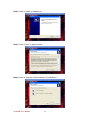


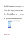


![[SPT-3000] e](http://vs1.manualzilla.com/store/data/005667089_1-a5f3766b3193f6552f250995926a69c5-150x150.png)