1
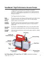
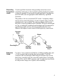
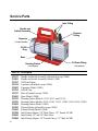
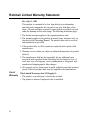
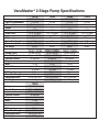
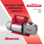
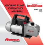
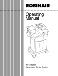
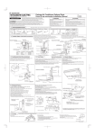
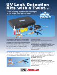
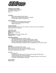
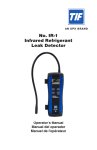
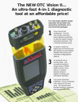
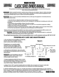
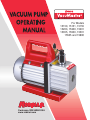
For Models
15150, 15151, 15155
15203, 15300, 15301
15355, 15500, 15501
15505 and 15800
Owatonna, MN 55060 USA
www.robinair.com
SAFETY PRECAUTIONS
WARNING! To prevent personal injury,
Wear goggles when working with refrigerants. Contact with
refrigerants may cause injury.
Incorrect use or connections may cause electrical shock hazards.
Read and follow the instructions carefully, and take precautions to
avoid electrical shock hazards. Confirm that all associated devices
are grounded correctly before energizing circuits.
Normal operating temperature will cause certain external portions of
the pump to be hot to the touch. Do not touch the pump housing or
motor during operation.
For use on A/C-R systems using CFCs, HCFCs, and HFCs in conjunction
with mineral oil, ester oil, alkylbenzene oil, and PAG oil as lubricants.
Not for use with ammonia or lithium bromide systems. Not for use with
flammable refrigerants.
VacuMaster® High Performance Vacuum Pumps
Congratulations on purchasing one of Robinair’s top quality
VacuMaster® vacuum pumps. Your pump has been engineered specifically for air conditioning and refrigeration service, and is built for fast,
thorough evacuation.
You’ll appreciate these key features . . .
High
Vacuum
Rating
The two-stage rotary vane design provides powerful, quiet, high vacuum
capability and ensures moisture removal, while the high pumping
capacity reduces evacuation time.
Lifetime
Filtration
The intake screen prevents foreign matter from entering the pumping
chamber, and an internal exhaust filter separates oil vapor from the
exhaust flow.
Sure-Grip
Handle
The one-piece, molded handle makes it easy to carry the pump to and
from job sites, and the handle stays cool to the touch during operation.
Compact
Design
Aluminum housing and rotary vanes keep the pump weight low, making
it easy to carry.
Inlet Fitting
Handle and
Switch Assembly
Exhaust Fitting
Capacitor
(under handle)
Sight Glass
Oil Fill
Plug
Base
Housing Gasket
Oil Drain Fitting
(not shown)
(not shown)
Inlet Fitting Adapter, 3/8" Female Flare x 1/2" ACME (included but not shown).
522683 Rev. F, 11-11-13
1
Before using your vacuum pump . . .
Note about Motor Voltage Connections:
In all cases, motors are designed for operating voltages plus or minus
10% of the normal rating (see Pump Specifications). Single voltage
motors are supplied fully connected and ready to operate.
1. Confirm that the voltage and frequency at the outlet match the specifications on the pump motor decal.
2. Confirm the ON-OFF switch is in the OFF position before you plug the
pump into an outlet.
3. Remove and discard the exhaust plug from the exhaust fitting.
4. The pump is shipped without oil in the reservoir. Before starting the
pump, fill it with oil. Remove the OIL FILL cap (red plastic plug at the
front of the handle), and add oil until oil appears in the bottom of the sight
glass. For oil capacities, refer to Pump Specifications in this manual.
5. Replace the OIL FILL cap, and remove the cap from one of the inlet ports.
6. Turn the motor switch to ON.
7. When the pump runs smoothly, replace the cap on the inlet port. This
may take from two to 30 seconds, depending on the ambient temperature.
8. After the pump has run for approximately one minute, check the sight
glass for the correct oil level — oil should be even with the sight glass
OIL LEVEL line. With the pump off, add oil if necessary.
Note: When the pump is running, the oil level should be even with the
line on the sight glass. Underfilling the pump will result in poor vacuum
performance; overfilling can result in oil blowing from the exhaust.
Your pump is now ready to evacuate air conditioning and refrigeration
systems. Follow normal service procedures and the A/C-R manufacturer’s instructions for connections to the system.
IMPORTANT: Before connecting your vacuum pump to an A/C-R system,
remove refrigerant from the system in an accepted manner.
Damage to the pump may occur if evacuation is started while the
system is under high pressure. Robinair recommends the use of
its Refrigerant Recovery and Recycling equipment.
2
To shut down the pump after use . . .
To help prolong pump life and promote easy starting, follow these
procedures for shutdown:
1. Close the manifold valve between the pump and the system.
2. Remove the hose from the pump inlet.
3. Cap the inlet port to prevent any contamination or loose particles from
entering the port.
To maintain your high vacuum pump . . .
Vacuum
Pump Oil
For maximum performance, Robinair recommends changing vacuum
pump oil after each use.
The condition and type of oil used in any high vacuum pump are
extremely important in determining the ultimate attainable vacuum.
Robinair recommends the use of its Premium High Vacuum Pump Oil.
This oil has been specifically blended to maintain maximum viscosity at
normal running temperatures and to improve cold weather starts.
Robinair Premium High Vacuum Pump Oil is available in handy quart
containers or in convenient gallon containers. Order by part number:
13119 — Pint (shipped 12 pints per case)
13203 — Quart (shipped 12 quarts per case)
13204 — Gallon (shipped 4 gallons per case)
1. Confirm the pump is warmed up. (The pump should have run for apOil
proximately one minute.)
Change
Procedure 2. Remove the OIL DRAIN cap. Drain contaminated oil into a suitable
container, and dispose of it according to local, state, and federal regulations. Oil can be forced from the pump by opening the inlet and partially
blocking the exhaust with a cloth while the pump is running. Do not
operate the pump for more than 20 seconds using this method.
3. When the flow of oil has stopped, tilt the pump forward to drain
residual oil.
3
4. Replace the OIL DRAIN cap.
Oil
Change
5. Remove the OIL FILL cap, and fill the reservoir with new vacuum pump
Procedure
oil until the oil appears at the bottom of the sight glass. For oil capacities,
contd.
refer to Pump Specifications in this manual.
6. Verify the inlet ports are capped; then turn ON the pump. Allow it to run
for one minute, and check the oil level. If the oil is below the sight glass
OIL LEVEL line, add oil slowly (with the pump running) until the oil
reaches the OIL LEVEL line. Replace the OIL FILL cap, and confirm
the inlet is capped and the drain cap is tight.
7. a) If the oil is badly contaminated with the sludge that forms when water
is allowed to collect in the oil, you may need to remove the oil reservoir cover and wipe it out.
b) Another method of dealing with heavily contaminated oil is to force
the oil from the pump reservoir. To do this, allow the pump to run
until it is warmed up. While the pump is still running, remove the oil
drain cap. Slightly restrict the exhaust. This will back-pressure the oil
reservoir and force the oil from it, carrying more contaminants. When
the oil ceases to flow, turn off the pump.
Repeat this procedure as required until the contamination is removed.
Replace the OIL DRAIN cap, and refill the reservoir until the oil
appears at the bottom of the sight glass with fresh pump oil. (See Step 4.)
Cleaning
the Pump
Clean the pump with soap and water only. Do not use commercial
cleaners that contain degreasing agents.
Grounding This product must be grounded. In the event of an electrical short,
Instructions grounding reduces the risk of electrical shock by providing an escape
wire for the electric current. This product is equipped with a power cord
having a grounding wire with an appropriate grounding plug. The outlet
used must be correctly installed and grounded according to local codes
and ordinances.
WARNING : Incorrect installation of the grounding plug will
result in electrical shock. When repair or replacement of the power
cord or plug is required, do NOT connect the grounding wire to
either flat blade terminal. The wire with green insulation (with or
without yellow stripes) is the grounding wire.
4
Grounding Consult a qualified electrician when grounding instructions are not
Instructions completely understood, or when in doubt regarding whether the product
contd.
is correctly grounded. Do not modify the plug provided; if the plug does
not fit the outlet, have an appropriate outlet installed by a qualified
electrician.
This product is for use on a nominal 120V circuit. A temporary adapter
may be used to connect this plug to a 2-pole receptacle when a correctly
grounded outlet is not available. The temporary adapter shall be used
only until a correctly grounded outlet is installed. The green colored rigid
ear, lug, or similar part extending from the adapter must be connected to
a permanent ground, such as a correctly grounded outlet box cover.
Whenever the adapter is used, it must be held in place by a metal screw.
Grounded
Outlet
Grounding Pin
Extension
Cords
Adapter
Metal
Screw
Grounded
Outlet Box
Tab for
Grounding
Screw
Use only a 3-wire extension cord that has a 3-blade grounding plug, and
a 3-slot receptacle that accepts the plug on the product. Verify the
extension cord is not damaged. When using an extension cord, use one
that is heavy enough to carry the current the product draws. For lengths
less than 25 ft., use 18 AWG extension cords. An undersized cord results
in a drop in line voltage, loss of power, and overheating.
5
Service Parts
Inlet Fitting
Handle and
Switch Assembly
Exhaust
Fitting
Capacitor
(under handle)
Oil Fill
Plug
Base
Housing Gasket
Oil Drain Fitting
(not shown)
(not shown)
Part No. Description
523192
535491
523193
523194
535492
523195
523197
535493
523199
523201
535494
523203
535495
523208
525402
525488
6
Handle and Switch Assembly (all models except 15800)
Handle and Switch Assembly (Model 15800)
Oil Drain Fitting
Capacitor (all models except 15800)
Capacitor (Model 15800)
Oil Fill Plug
Base (all models except 15800)
Base (Model 15800)
Housing Gasket (Models 15150, 15151, and 15155)
Housing Gasket (Models 15300, 15301, 15355, 15500, 15501, 15505, 15203)
Housing Gasket (Model 15800)
Exhaust Fitting (all models except 15800)
Exhaust Fitting (Model 15800)
Inlet Fitting Adapter, 3/8" Male Flare x 1/2" Female ACME
Inlet Fitting, 1/4" and 3/8" Male Flare
Inlet Fitting Adapter, 3/8" Female Flare x 1/2" Male ACME
Troubleshooting Guide
Your VacuMaster® pump has been designed for dependable use and long
life. If something should go wrong, however, the following guide will help
you get the pump back into service as quickly as possible.
If disassembly of the pump is required, check your warranty. The warranty
may be voided by misuse or customer tampering that results in the pump
being inoperable.
Failure
To Start
1. Check line voltage. Robinair VacuMaster® pumps are designed to start at
+10% line voltage (loaded) at 41o F (5° C). At extremes, however,
switching between the start and run windings may occur.
Oil
Leakage
1. Verify the oil is not a residual accumulation from spillage, etc.
Failure
To Pull
A Good
Vacuum
1. Confirm the vacuum gauge and all connections are in good condition and
leak-free. You can confirm leakage by monitoring the vacuum with a
thermistor gauge while applying vacuum pump oil at connections or
suspected leak points. The vacuum will improve briefly while the oil is
sealing the leak.
2. If leakage exists, the module cover gasket or the shaft seal may need to
be replaced. If leakage exists in the area of the oil drain plug, you may
need to reseal the plug using a commercial pipe thread sealer.
2. Verify the pump oil is clean. A badly contaminated pump may require
several oil flushes. See OIL CHANGE PROCEDURE.
Note: Use only high vacuum pump oil such as Robinair’s Premium High
Vacuum Pump Oil. Other oils will prevent pull-down to a deep vacuum.
3. Verify the oil is at the correct level. For maximum pump operation, the
oil must be even with the OIL LEVEL line on the sight glass when the
pump is running. See OIL CHANGE PROCEDURE. Do not overfill —
operating temperatures will cause the oil to expand, so it will appear at a
higher level than when the pump is not running. To
check the oil level, start the pump with the inlet capped.
Check the oil level in the sight glass. Add oil if necessary.
When You
Need Help
If these procedures do not correct the problem, contact
your nearest Robinair distributor, or call Robinair’s
toll-free service line for further information:
800-822-5561
7
Robinair Limited Warranty Statement
Rev. July 11, 2003
Out of
Warranty
8
This product is warranted to be free from defects in workmanship,
materials, and components for a period of one year from date of purchase. All parts and labor required to repair defective products covered
under the warranty will be at no charge. The following restrictions apply:
1. The limited warranty applies to the original purchaser only.
2. The warranty applies to the product in normal usage situations only, as
described in the Operating Manual. The product must also be serviced
and maintained as specified.
3. If the product fails, it will be repaired or replaced at the option of the
manufacturer.
4. Warranty service claims are subject to authorized inspection for product
defect(s).
5. The manufacturer shall not be responsible for any additional costs
associated with a product failure including, but not limited to, loss of
work time, loss of refrigerant, cross-contamination of refrigerant, and
unauthorized shipping and/or labor charges.
6. All warranty service claims must be made within the specified warranty
period. Proof-of-purchase date must be supplied to the manufacturer.
This Limited Warranty does NOT apply if:
• The product, or product part, is broken by accident.
• The product is misused, tampered with, or modified.
VacuMaster® 2-Stage Pump Specifications
1515015300 15500
15800
Voltage
115V / 60 Hz
115V / 60 Hz
115V / 60 Hz
120V / 60 Hz
Free Air Displacement
1.5 CFM
3 CFM
5 CFM
8 CFM
Ultimate Vacuum
50 microns
40 microns
40 microns
40 microns
Stages
22 22
Motor
1/4 HP
1/3 HP
1/3 HP
1 HP
1/4" & 3/8" Flare,
1/4" & 3/8" Flare,
1/4" & 3/8" Flare,
1/4" & 3/8" Flare,
Intake Ports
1/2" ACME
1/2" ACME
1/2" ACME
1/2" ACME
Oil Capacity
7.4 oz.
7.4 oz.
7.4 oz.
18.6 oz.
Power Cord Length
6 ft.
6 ft.
6 ft.
6 ft.
Dimensions (in.)
12.5 x 4.75 x 9.5
13.25 x 5 x 10
13.25 x 5 x 10
15.5 x 5.75 x 10.25
Net Weight
22 lbs.
28 lbs.
28 lbs.
38 lbs.
15151 / 15155
15301 / 15355
15501 / 15505
Voltage (220V)
50 Hz / 60 Hz
50 Hz / 60 Hz
50 Hz / 60 Hz
Free Air Displacement
35 lpm / 1.5 CFM
71 lpm / 3 CFM
118 lpm / 5 CFM
Ultimate Vacuum
50 microns
40 microns
40 microns
Stages
22 2
Motor
1/4 HP
1/3 HP
1/3 HP
1/4" & 3/8" Flare,
1/4" & 3/8" Flare,
1/4" & 3/8" Flare,
Intake Ports
1/2" ACME
1/2" ACME
1/2" ACME
Oil Capacity
220 ml
220 ml
220 ml
Power Cord Length
1.82 m
1.82 m
1.82 m
Dimensions (mm)
315 x 120 x 240
336 x 123 x 255
336 x 123 x 255
Net Weight
9.6 kg
12.5 kg
12.5 kg
15203
Voltage
100V / 50–60 Hz
Free Air Displacement
85 lpm @ 60 Hz
71 lpm @ 50 Hz
Ultimate Vacuum
40 microns
Stages
2
Motor
1/3 HP
1/4" & 3/8" Flare,
Intake Ports
1/2" ACME
Oil Capacity
220 ml
Power Cord Length
1.82 m
Dimensions (mm)
336 x 123 x 255
Net Weight
12.5 kg
Please register your product at www.robinair.com
Due to ongoing product improvements,
we reserve the right to change design,
specifications, and materials without notice.
655 Eisenhower Drive
Owatonna, MN 55060 USA
Technical Services: 1-800-822-5561
Fax: 1-866-259-1241
Customer Service: 1-800-533-6127
Fax: 1-800-322-2890
Web Site: www.robinair. com
522683 Rev. F November 11, 2013
© Bosch Automotive Service Solutions LLC