Transcript
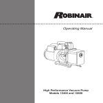
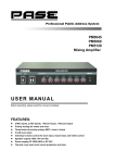
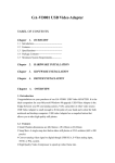
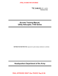
GB
RG79V973H01
Package Air Conditioner Optional Parts
Drain lift up mechanism Installation Manual
* Before installation, read this manual and the installation manual
of the indoor unit carefully.
* Be sure to read these safety precautions thoroughly to ensure correct installation.
Safety Precautions
* The precautions described here are important for your safety and must be followed.
* The following two symbols are used to denote dangers that may be caused by incorrect
installation. They are classified according to the degree of danger.
WARNING
CAUTION
Type:
PAC-SH83DM-E
PAC-SH84DM-E
PAC-SH85DM-E
CAUTION
WARNING
This symbol denotes what could lead to serious injury or death if you install the mechanism incorrectly.
Ask your dealer or technical representative to
install the unit.
Any deficiency caused by your own installation may
result in water leakage, an electric shock or fire.
Make sure that the refrigerant pipes are insulated in order to prevent
condensation.
Incomplete insulation may cause condensation on the surface of pipes,
wetting of the ceiling, floor and other important properties.
Ensure that installatiom work is done correctly
following this installation manual.
Any deficiency caused by installation may result
in water leakage, an electric shock or fire.
Make sure that the drainage pipes are carried out correctly following this
manual and that it is insulated in order to prevent condensetion.
Any dificiency caused by piping may result in water leakage, wetting of the
ceiling, floor and other personal properties.
This symbol denotes what could lead to personal injury or damage to your property if you install the mechanism incorrectly.
* After the installation has been completed,carry out a test run and checkthat there are no abnormalities. At the same time explain
the safety precautions, method of operation and maintenance to your customers, and hand this manual over to them.
* The customer id requested to keep this manual together with the user’s manual in a safe place. If another user is going to use this
unit, make sure that the manuals are handed over to him.
1 Confirming Supplied Accessories
* Before starting installation, make sure that the following accessories are present.
1 Drain lift up mechanism 2 Attachment 3 Screws (4×10) 4 VP-20 pipe 5 Pipe cover 6 Flexible hose 7 Fastener
8 L-shaped pipe (gas pipe) 9 L-shaped pipe (liquid pipe)
0 Insulator A
1 Insulator B
6t×220×80
3t×250×120
(For internal insulation)(For external insulation)
Drainage outlet
(for VP-20) 112
Viewed from the Front
L-shaped pipe 9
(liquid pipe)
47
L-shaped pipe 8
(gas pipe)
100
* Please refer to the installation manual of an indoor unit for details.
* The L-shaped pipes there are bringing are corresponding to either refrigerant plumbing.
W1 In case of accessory parts VP-20pipe 4 and pipe cover 5 do not have enough length because
the lifting height is high, please supply locally.
[ Unit:mm ]
Elbow pipe
(locally supplied)
VP-20pipe 4 W1
(outer diameter:[26)
(pipe cover 5)
W1
134
210
Attachment 2
Liquid pipe
L-shaped pipe 8,9
(gas pipe, liquid pipe)
Drain lift up mechanism 1
Gas pipe
VP-20pipe
Positions
(locally supplied)
Viewed from the Right
73
Drain lift up mechanism 1
* This drain lift up mechanism must be installed inside an indoor unit.
* Installing this drain lift up mechanism limits to arrange the refrigerant pipe only upward.
* To facilitate installation of the drain lift up mechanism, it should be installed before indoor unit.
* The size of the plumbing that must connect, by the refrigerant kind of the indoor unit
that corresponds in the case of PAC-SH85DM-E, changes.
Fixing hole
[9.52
[6.35/[9.52
230
108.5
[15.88
[15.88
Attachment 2
Drain lift up mechanism Model
PAC-SH83
PAC-SH84
PAC-SH85
Fixing screw 3
Drainage plug
61
Ceiling hole(2-[100)
Knockout hole on the
indoor unit(for upper piping)
41
Liquid Pipe
[6.35
Right side of
the indoor
unit
Fixing screw 3
〈Table 1〉
Gas pipe
120
9
Fixing screw 3
Flexible hose 6
[12.7
Rear side of the indoor unit
Drain lift up
mechanism
1
Right side panel
Knockout hole on the indoor
unit(for upper piping)
of Holes on the Ceiling
70
Viewed from the Top
PAC-SH83/84 ×1 For the insulation of L-shaped For the insulation of L-shaped
pipes ⑧ and ⑨ and the
pipes ⑧ and ⑨ and the
PAC-SH85 ×2 refrigerant pipes.
×2
×2 refrigerant pipes.
×1
×1
130
Installation Diagram of the Drain lift up mechanism
×1
Max. 600
2
For insulation of
VP20 pipe④ ×1
×1
221
For the installation of
drain lift up mechanism①
1 Drain lift up
×1 mechanism fixture ×1
×6
126
Drain connecting hole on
the indoor unit
Drain connecting hole
Flexible hose 6
40
27
W In case of accessory parts VP-20pipe 4
and pipe cover 5 do not have enough
length because the lifting height is high,
please purchase procure supply locally. *Refer to the installation manual of the indoor unit together with this manual.
1.Remove the intake grille and side panel. (Refer to the indoor unit installation manual.)
*Perform the work after checking that the power supply is off.
2.Prepare the knockout hole to be used for the upper piping of the indoor unit.
*For details on piping, refer to the installation manual of the indoor unit.
1.Remove the beam.
3.Fix the attachment 2 with the fixing screws 3 (×2)
1.Apply vinyl chloride type abhesive to the drainage outlet of the drain lift up mechanism ① , then insert
2.Remove the electric parts cover.
4.Fix the drain lift up mechanism 1 with the fixing screws 3 (×4)
the VP-20 pipe ④ into it, (30mm deep)
3.Pull the electric parts box downwards.
2.Connect the VP20 pipe ④ and existing drain pipe using a 90-degree elbow etc. and adhesive.
4.Connect the lead wire of drain lift up mechanism to the CNP and CN4F connectors
3.Cover the VP-20 pipe ④ with the pipe cover ⑤.
provided on the control PCB of the indoor unit.
4.Apply vinyl chloride type adhesive to the drain lift up mechanism ① and drain connecting hole on the
5.Tie up the lead wires with the fastener 7 so that the wires do not come apart inside
Drain lift up mechanism 1
indoor unit, then insert the flexible hose ⑥ into them. Take care that the hose does not twist.
Fixing screws 3
the electric parts box.
*Insulate all pipes, from the drain lift up mechanism up to the outside.
6.When the wiring is finished, re-install the electric parts box, its cover and the beam.
Fixing screws 3
3
Installing the Drain lift up mechanism
5
6
Drain Piping
Electric Wiring
VP-20 pipe
(locally supplied)
Elbow (locally supplied)
Attachment 2
Max. 600mm
W
VP-20 pipe 4
Viewed from the Right
W
Pipe cover 5
Push to the end.
Convex
for locating
Drain lift up mechanism ①
Rear side panel
(metal plate)
Drain lift up mechanism 1
Electric parts box
Electric parts cover
(An electric wiring diagram
is provided on the back.)
Fixing screws 3
Knockout hole
for upper piping
Drain connecting hole on
the indoor unit
Right side panel
(metal plate)
Beam
Flexible hose 6
Apply vinyl chloride type adhesive to these areas.
Lead wire of the drain lift up mechanism
4
[Make sure to follow the following points during drain piping.]
Refrigerant Piping
*For details on piping, refer to the installation manual of the indoor unit.
[With the stop valve of the outdoor unit fully closed]
1.Apply lubricant to the flare sheet of the L-shaped pipes (gas pipe, liquid pipe) 89.
2.Remove the flare nut and cap from the indoor unit.
3.Apply lubricant to the flare sheet connecting section of the indoor unit.
4.Connect the L-shaped pipes (gas pipe, liquid pipes) 8 and 9 quickly.
5.Fit the removed flare nut to the existing pipes and carry out flaring.
6.Connect the L-shaped pipes with the existing pipes in the same way.
7.Cover each connection with heat insulator 01.
*Drain lifting height must be less than 600mm.
*Incline the drain pipe downwards (1/100 or more) to the drainage side (outdoor).
*Do not create traps or peaks.
*Keep the horizontal piping within 20m. Use fixtures to prevent the pipe from waving.
*Do not install air vent pipes. The drainage may spout out.
*Use general-purpose hard vinyl chloride pipes (outer diameter:[26) and apply vinyl chloride type adhesive
to prevent any leakage.
*Cover with insulator (made of foamed polyethylene, with specific gravity of 0.03 thickness of 9mm or more).
*Do not install odor trap at the drain outlet.
*Locate the end of pipe at a point where odor is unlikely to occur.
*Do not insert the pipe directly into a drainage ditch where sulfur gas may be produced.
*Use VP-30 pipes for centralized piping. Install the centralized drain pipe approximately
10cm below the output of pipes connected from the drain lift up mechanism.
[After the refrigerant circuit is complete]
8.Vacuumize the refrigerant lines through the service port of the liquid stop valve.
9.Fully open the stop valves (both liquid and gas).
* The method for oparating the stop valve is described on the outdoor unit installation manual.
Support
CNP(pump)
Connect to the blue
connector.
Air vent
Cover this part with insulator
A 0 and then cover it over
with insulator B 1
Wrap this part with the insulator
that comes with the indoor unit.
Control PCB
After the box is re-installed,secure
the excess part of the lead wire with
the clamp located on the right of
the electric parts box.
Electric parts box
(Possible to fix temporarily hanging the lug that is
on back of the electric parts box on the panel behind)
Use the flare nut which has
been removed from
the indoor unit.
lnsulator A,B 01
Fix the lead wire
Tie up with existing lead wire
Fastener 7
1.5~2m
Refrigerant pipes(locally supplied)
WApply the ester-oil or ether-oil
or alkylbenzene
(locally supplied)
Fix with the clamp located on
upper right of the electric parts box.
Downward
inclination
(1/100 or more)
Re-rizing
Odor trap
Make the drop as long as possible(approx. 10cm)
CN4F (float switch)
Connect to the white connector.
*A jumper connector is used in place of CN4F at
the time of shipment, so replace it with CN4F
Drain lift up mechanism
VP-30
[Example of centralized piping]
Drain lift up mechanism
Indoor unit
7
Test Run
L-shaped pipes 8,9
(gas pipe, liquid pipe)
Downward
inclination
(1/100 or more)
*The positions of the connectors which must be connected to the control PCB in certain
models differ from those specified in the above diagram. Make sure that the lead wire
are connected to CNP and CN4F connectors.
*Through this test run, check that drainage is discharged properly and that there is no water leakage from any of the connections.
*Refer to the installation manual of the indoor unit together with this manual.
2.Carrying out a test run
(1) Turn the power ON.
(2) Press the TEST RUN button on the remote controller twice.
(3) Press the MODE button to select cooling mode.
*The drain lift up mechanism will be activated to start discharging the water.
(4) Check whether water is discharged properly.
(5) Press the POWER ON/OFF button to cancel the test run.
(6) Turn the power OFF.
1. Supplying water
Supply approximately 1000cc of water to the air outlet.
Air outlet
Water supply pump
3.Re-install each part after checking.
*If the drain lift up mechanism is installed at the time of the year
when heating is used, make sure that the water for the drain check
has been removed.
After removal of the water, reinstall the drainage plug.
Drainage plug
Drain pan