1
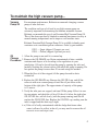
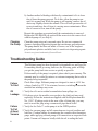
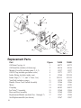
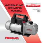
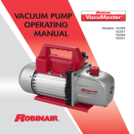
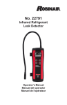
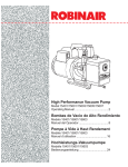
Operating Manual
High Performance Vacuum Pump
Models 15400 and 15600
Robinair High Performance Vacuum Pumps
Congratulations on purchasing one of Robinair’s top quality vacuum
pumps. Your pump has been engineered specifically for air conditioning
and refrigeration service, and is built with Robinair’s proven offset rotary
vane for fast, thorough evacuation.
You’ll appreciate these key features...
Iso-ValveTM
Allows the pump to be shut off while still connected to the A/C-R
system, which is handy for checking rate of rise. With the valve handle in
the OPEN position, the pump is open to the system being evacuated. In
the CLOSED position, the pump is isolated from the system.
High
Vacuum
Rating
The two-stage, offset, rotary vane design provides powerful, quiet,
high vacuum capability and ensures moisture removal, while the high
pumping capacity reduces evacuation time.
Lifetime
Filtration
The intake filter prevents foreign matter from entering the pumping
chamber, and an internal exhaust filter separates oil vapor from the
exhaust flow.
Directed
Exhaust
Exhaust is expelled through the handle to direct it away from the service
technician.
Gas
Ballast
A precise amount of atmospheric air is introduced into the pump,
preventing condensation of moisture vapor and helping maintain the
purity of the pump oil. By using the gas ballast, the pump operates more
efficiently and pump life is extended.
Sure-Grip
Handle
The one-piece, molded handle makes it easy to carry the pump to and
from job sites, and the handle stays cool to the touch during operation.
Compact
Design
The pump measures just 151/2" long, while aluminum housing and offset
rotary vanes keep the pump weight low, making it easy to carry.
For use on A/C-R systems using CFCs, HCFCs, and HFCs in conjunction
with mineral oil, ester oil, alkylbenzene oil, and PAG oil as lubricants.
Not for use with ammonia or lithium bromide systems. Not for use with
flammable refrigerants.
1
12
11
1
2
3
4
10
9
5
8
7
Pump
Components
1. Intake Fitting
2. Gas Ballast Valve
(located beside handle base)
3. Oil Fill Port
4. Sight Glass
5. Die-Cast Aluminum Housing
6. Oil Drain
6
7. Molded Polycarbonate Base
8. Iso-ValveTM
(isolates the pump from the system)
9. High-Torque Motor
10. Power Switch
11. Through-The-Handle Exhaust
12. Sure-Grip Handle
WARNING!
2
Wear safety goggles when working with refrigerants. Contact with
refrigerants may cause eye injury.
Incorrect use or electrical connections may cause electrical shock.
Read and follow instructions carefully, and take precautions to avoid
electrical shock hazards. All associated devices must be correctly
grounded before energizing circuits.
Normal operating temperatures will cause certain external portions
of the pump to be hot to the touch. Do not touch the pump housing
or motor during operation.
Before using your vacuum pump...
CAUTION
Note on Motor Voltage Connections:
In all cases, motors are designed for operating voltages, plus or minus
10% of the normal rating (see SPECIFICATIONS). Single voltage
motors are supplied fully connected and ready to operate.
1.Verify the voltage and frequency at the outlet match the specifications on the
pump motor decal. Place the ON / OFF switch in the OFF position before
you plug the pump into an outlet. Verify the gas ballast valve is closed.
Remove and discard the exhaust plug from the end of the pump handle.
2.The pump is shipped without oil in the reservoir. Before starting the
pump, fill it with oil. Remove the OIL FILL cap (plastic plug directly in
front of the handle), and add oil until oil just shows in the bottom of the
sight glass. The approximate oil capacity of the pump is 15 ounces.
3.Replace the OIL FILL cap, and remove the cap from one of the inlet
ports. OPEN the Iso-Valve™. Turn ON the motor switch. When the
pump runs smoothly, CLOSE the Iso-Valve™, and replace the cap on the
inlet port. This may take from two to 30 seconds depending on ambient
temperature. After the pump runs for approximately one minute, check
the sight glass for the correct oil level — the oil should be even with the
sight glass OIL LEVEL line. Add oil if necessary.
Note: When the pump is running, the oil level should be even with
the line on the sight glass. Underfilling will result in poor vacuum
performance; overfilling can result in oil blowing from the exhaust.
Your pump is now ready to evacuate air conditioning and refrigeration
systems. Follow normal service procedures and the A/C-R
manufacturer’s instructions for connections to the system.
Before connecting your vacuum pump to an A/C-R system,
remove refrigerant from the system in an accepted manner
using an approved recovery unit. Damage to the pump may
occur if evacuation is started while the system is under high
pressure.
3
To use the gas ballast feature...
Moisture from the A/C-R system that is carried into the pump as a vapor
tends to condense into a liquid and combine with the vacuum pump oil.
When moisture contaminates the pump oil, it reduces the pump’s ability
to reach its ultimate deep vacuum level.
The gas ballast valve purges a small amount of atmospheric air through
the exhaust chamber. This extra volume of air mixes with the vapor
from the refrigerant system to prevent condensation and to help exhaust
moisture in the form of vapor from the pump.
The gas ballast valve is located beside the handle, opposite the inlet
fitting. To use the gas ballast, start the pump and open the gas ballast
valve until the system has reached 1000–3000 microns. Close the valve
to allow the pump to pull down to its ultimate vacuum level.
The gas ballast valve may be opened or closed at any time during pump
operation. It is fully open at two turns counterclockwise.
Note: Robinair recommends the use of a thermistor vacuum gauge to
most accurately measure vacuum levels.
To shut down the pump after use...
To prolong pump life and promote easy starting, follow these procedures
for shutdown:
1.Close the manifold valve between the pump and the system.
3.Remove the hose from the pump inlet.
4
2.Turn the Iso-Valve™ to the CLOSED position.
4.Turn the pump power switch to OFF. Return the Iso-Valve™ to the
OPEN position for a few seconds to relieve any vacuum inside the pump.
5.Cap the inlet port to prevent any contamination or loose particles from
entering the port.
To maintain the high vacuum pump...
Vacuum
Pump Oil
For maximum performance, Robinair recommends changing vacuum
pump oil after each use.
Robinair Premium High Vacuum Pump Oil is available in handy quart
containers or in convenient gallon containers. Order by part number:
The condition and type of oil used in any high vacuum pump are
extremely important in determining the ultimate attainable vacuum.
Robinair recommends the use of our Premium High Vacuum Pump Oil.
This oil has been specifically blended to maintain maximum viscosity at
normal running temperatures and to improve cold weather starts.
13203 — Quart(shipped 12 quarts per case)
13204 — Gallon (shipped 4 gallons per case)
Oil
1.Allow the pump to run until it is warmed up.
Change
2.Remove the OIL DRAIN cap. Drain contaminated oil into a suitable
Procedure
container and dispose of it according to the regulations in your
jurisdiction. Oil can be forced from the pump by opening the inlet and
partially blocking the exhaust with a cloth while the pump is running. Do
not operate the pump for more than 20 seconds using this method.
3.When the flow of oil has stopped, tilt the pump forward to drain
residual oil.
4.Replace the OIL DRAIN cap. Remove the OIL FILL cap, and fill the
reservoir with new vacuum pump oil until the oil just shows at the
bottom of the sight glass. The approximate oil capacity of the pump
is 15 ounces.
5.Verify the inlet ports are capped, and turn ON the pump. Allow it to run
for one minute, and check the oil level. If the oil is below the sight glass
OIL LEVEL line, add oil slowly (with the pump running) until the oil
reaches the OIL LEVEL line. Replace the OIL FILL cap, making sure the
inlet is capped and the drain cap is tight.
6.a)If the oil is badly contaminated with the sludge that forms when
water is allowed to collect in the oil, you may need to remove the oil
reservoir cover and wipe it out.
5
b)Another method of dealing with heavily contaminated oil is to force
the oil from the pump reservoir. To do this, allow the pump to run
until it is warmed up. While the pump is still running, remove the oil
drain cap. Slightly restrict the exhaust. This will back-pressure the oil
reservoir and force the oil from it, carrying more contaminants. When
the oil ceases to flow, turn off the pump.
Cleaning
the Pump
Repeat this procedure as required until the contamination is removed.
Replace the OIL DRAIN cap, and refill the reservoir to the correct level
with fresh pump oil (see Step 4).
Clean the pump using only soap and water. Do not use commercial
cleaners containing degreasing agents that can damage polycarbonates.
The pump handle and base are made of Lexan®, one of the toughest
polycarbonate plastics available, but it is sensitive to degreasing agents.
*Lexan is a registered trademark of General Electric.
Troubleshooting Guide
Failure
To Start
This Robinair pump has been designed for dependable use and long life.
If something should go wrong, however, the following guide will help
you get the pump back into service as quickly as possible.
If disassembly of the pump is required, please check your warranty. The
warranty may be voided by misuse or customer tampering that results in
the pump being inoperable.
Check line voltage. Robinair pumps are designed to start at +10% line
voltage (loaded) at 32o F. At extremes, however, switching between the
start and run windings may occur.
Oil
Leakage
1.Verify the oil is not a residual accumulation from spillage, etc.
Failure
To
Pull
A Good
Vacuum
1.Verify the Iso-Valve™ on the pump is in the OPEN position.
6
2.If leakage exists, the module cover gasket or the shaft seal may need
replacing. Follow the instructions supplied with Seal Replacement Kit
No. 15367. If leakage exists in the area of the oil drain plug, you may
need to reseal the plug using a commercial pipe thread sealer.
2.Verify the vacuum gauge and all connections are in good conditon and
leak-free. Confirm leakage by monitoring the vacuum with a thermistor
gauge while applying vacuum pump oil at connections or suspected leak
points. Vacuum will improve briefly while the oil is sealing the leak.
When
You
Need Help
3.Verify the pump oil is clean. A badly contaminated pump may require
several oil flushes. See OIL CHANGE PROCEDURE.
Note: Use only high vacuum pump oil such as Robinair’s Premium High
Vacuum Pump Oil. Other oils will prevent pull-down to a deep vacuum.
4.Verify the gas ballast knob is tightly closed.
5.Verify the oil is at the correct level. For maximum pump operation, the
oil must be even with the OIL LEVEL line on the sight glass when the
pump is running. See OIL CHANGE PROCEDURE. Do not overfill —
operating temperatures will cause the oil to expand so it will appear at a
higher level than when the pump is not running. To check the oil level,
start the pump with the inlet capped. Check the oil level in the sight
glass. Add oil if necessary.
If these procedures do not correct the problem,
contact your nearest Robinair distributor. The
distributor may recommend an additional
replacement part (this manual contains a
replacement parts list) or suggest you send your
pump to the nearest authorized service center.
Call Robinair’s toll-free Service Line for further
information: You may also visit our website at
www.robinair.com for technical support.
800-822-5561
Warranty Coverage
Out
of
Warranty
Robinair vacuum pumps are warranted against defects in material and
workmanship for one year of normal use from the date of purchase. See
your distributor for warranty details.
A pump that is no longer covered by the one-year warranty period, and
which fails to operate correctly, should be returned to the distributor
or an authorized Robinair service center with a complete, written
explanation of the problem. Before returning an out-of-warranty pump,
review maintenance procedures to avoid an unnecessary return. Note
that contaminated oil or an incorrect oil level will adversely affect pump
performance. Replacement parts are available for doing your own service;
however, this should be considered only in out-of-warranty situations.
Product
Registration Register your vacuum pump at www.robinair.com.
7
11
12
9
8
9
9
7
13
6
14
5
4
15
16
Replacement Parts
Part
Oil Drain Cap (qty. 6)
Oil Drain Kit (includes oil drain cap)
Module Cover Kit (includes items 2, 4, 5)
Oil Fill Cap (includes gas ballast valve)
Intake Fitting (includes intake caps)
Intake Caps (1/4", 3/8", and 1/2" flare; 1 ea.)
Vent Bolt (includes o-rings)
Handle, Power Cord, Switch Assembly
Motor
Coupling
Iso-Valve™ Assembly
Base and Foot Assembly
Replacement Module (includes Nos. 1 through 7)
Seal Replacement Kit (not shown)
8
17
Figure
1
2
3
4
8
9
11
12
13
14
15
16
17
--
3
2
15400
40572
48116
15337
15371
15364
555133
15338
15366
15365
48103
15368
15369
15547
15367
1
15600
40572
48116
15337
15371
555124
555133
15338
15366
15370
48103
15368
15369
15548
15367
Pump Specifications
Model
Free Air Displacement
Stages
Motor Speed
Voltage +10%
Factory Micron Rating
Approximate Oil Capacity
Weight
Width
Height
Length
Intake
Min. Starting Temperature
(at 90% Voltage)
Motor Size
Operating Temp.
15400
4 CFM
2
1725 RPM
115V 60 Hz
15 microns
15 oz.
27 lbs.
55/8 in.
93/4 in.
151/2 in.
1
/2" and 1/4" SAE MFL
15600
6 CFM
2
1725 RPM
115V 60 Hz
15 microns
15 oz.
27 lbs.
55/8 in.
93/4 in.
151/2 in.
1
/4", 3/8", and 1/2" SAE MFL
32° F
/2 hp; capacitor start
155° F
32° F
1
/2 hp; capacitor start
155° F
1
Note: 1. All motors are internally protected (automatic reset).
2. Operating temperatures are typical for normal operating conditions.
Due to ongoing product improvements, we reserve the right
to change design, specifications, and materials without notice.
655 Eisenhower Drive
Owatonna, MN 55060 USA
Technical Services: 1-800-822-5561
Fax: 1-866-259-1241
Customer Service: 1-800-533-6127
Fax: 1-800-283-8665
Web Site: www.robinair. com
110973 Rev. F June 17, 2013
© Bosch Automotive Service Solutions