1
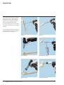
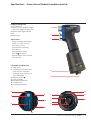
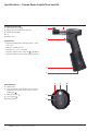
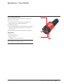
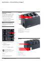
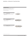
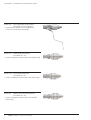
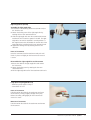
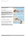
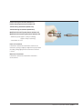
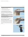
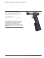
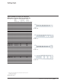
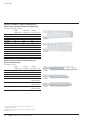
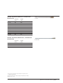
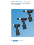
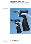
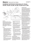
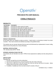
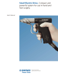
Trauma Recon System (TRS).
Battery-driven power system designed
for traumatology and arthroplasty.
User’s Manual
Table of Contents
Introduction
Applications
2
Specifications
TRS Handpieces and Lids
3
Power Module
5
Universal Battery Charger
6
Attachments for Trauma Recon System
7
Operating Instructions
Product Information
Universal Battery Charger II
12
Power Module
15
TRS Modular Lids
20
Attachments
21
Saw Attachments
29
Radiolucent Drive
33
TRS Recon Saw Lid
36
TRS Recon Saw
37
Troubleshooting
39
Technical Data
45
Ordering Information
47
Cutting Tools
49
Image intensifier control
Trauma Recon System User’s Manual Synthes
Applications
The Trauma Recon System is a batterydriven power system with a range of
attachments and accessories for use
in general traumatology and arthroplasty, including drilling, sawing,
inserting/ removing K-wires, DHS / DCS,
RIA, and intramedullary and acetabular
reaming.
The TRS Recon Sagittal Saw is a dedicated handpiece specifically designed
for knee and hip arthroplasty.
2
Drilling
Reaming
K-wire insertion
Bone graft harvesting
Sagittal sawing
Reciprocating sawing
Synthes Trauma Recon System User’s Manual
Specifications — Trauma Recon Modular Handpiece and Lid
Handpiece (05.001.201)
1 Coupling sleeve
2 Instant reverse or oscillation trigger
(when both triggers are depressed)
3 Variable-speed trigger (forward)
4 Lid
5 Mode switch
1
2
3
Specifications
– Weight (including power module
and lid): 1.31 kg (2 lb. 14 oz.)
– Cannulation: 4.1 mm
– Speed (without attachment):
0 –18,000 rpm
– Protection against electric
shock: BF , EN 60601-1
– Protection against water intrusion:
IPX4, EN 60529
Lids (05.001.227/05.001.231)
6 Mode switch
7 Safety button for mode selector
switch (prevents inadvertent
opening of the lid; only press to
set to UNLOCK )
8 UNLOCK position
9 LOCK position
10 Drilling/reaming position
11 Sawing position
12 Oscillating drill position
4
5
8
10
9
7
11
9
7
10
6
12
8
6
11
12
Trauma Recon System User’s Manual Synthes
3
Specifications — Trauma Recon Sagittal Saw and Lid
Handpiece (05.001.240)
1 Saw blade screw coupling
2 Sliding sleeve for positioning saw head
3 Variable-speed trigger
4 Lid
5 Mode switch
Specifications
– Weight (including power module and lid): 1.76 kg
(3 lb. 9 oz.)
– Frequency: 11,000 osc /min
– Deflection: 4.5° (2.25° each side)
– Protection against electric shock: BF
, EN 60601-1
– Protection against water intrusion: IPX4, EN 60529
2
1
3
4
5
Lid (05.001.241)
6 Mode switch
7 Safety button for mode selector switch (prevents
inadvertent opening of the lid; only press to set
to UNLOCK )
8 UNLOCK position
9 LOCK position
10 Sawing position
4
Synthes Trauma Recon System User’s Manual
8
7
6
9
10
Specifications — Power Module
Power module (05.001.202)
The power module includes the motor, circuit board, and
lithium ion (Li-ion) battery.
1 Information button (when pressed, the charge status
display and / or service indicator illuminates)
2 Charge status display
3 Service indicator (if/when red LED illuminates, immediately
send the power module to the Synthes Service Department for repair)
4 Lever to remove the power module from the handpiece
Specifications
– Voltage: 25.2 V
– Type: Li-ion (lithium ion)
– Capacity: 1.2 Ah
– Charging time: 60 minute maximum
3
2
1
4
Important: DO NOT STERILIZE POWER MODULE!
Power module will no longer function.
Trauma Recon System User’s Manual Synthes
5
Specifications — Universal Battery Charger II
Universal Battery Charger II
(05.001.204)
The Universal Battery Charger II includes
four independent charging bays. Each
charging bay has three slots for the
following batteries / power module:
Front view
– Battery Power Line Battery
– Trauma Recon System Power Module
– Small Battery Drive Battery
4
1
2
3
Note: The maximum charging time,
depending on the charge status and
type of battery/power module, is 45
to 80 minutes.
5
1
1
2
3
4
5
Charging bays (4)
Symbols for battery / power module type
ON / OFF display
Control display for each charging bay
Ventilation holes
2
3
1 Battery Power Line Battery (530.620)
2 Trauma Recon System Power Module
(05.001.202)
3 Small Battery Drive Battery
(532.003 or 532.033)
Complies with standards: UL 60601-1, 1st Edition
IEC 60601-1, 2nd Edition
10PB
Universal Battery Charger II
With respect to electrical shock, fire and
mechanical hazards only in accordance
with UL 60601-1/ CAN/CSA C22.2
No. 601.1
IEC 60601-1-2
IEC 60601-1-4
Please refer to the Universal Battery Charger II
User’s Manual for additional information.
6
Synthes Trauma Recon System User’s Manual
Rear view
6
7
8
9
6
7
8
9
Ventilation holes
Power switch
Fuses: 2 x 5 AT
Power cord connection
Specifications — Attachments for Trauma Recon System
Drilling speed attachments
All drilling speed attachments are geared to transfer the speed
of the drive unit, with a maximum speed of 1,450 rpm.*
Drilling speed attachments are etched with “DRILL” and
marked in blue color coding.
05.001.205
AO Quick Coupling
Cannulation: 2.1 mm
– Accepts cutting tools and instruments with AO quick
coupling fitting
05.001.206
Chuck with Key, Drill Speed
Cannulation: 4.1 mm
– Accepts round and triangular shafts: up to 7.3 mm
Includes key (510.191)
05.001.208
Chuck, Keyless, Drill Speed
Cannulation: 4.1 mm
– Accepts round and triangular shafts: up to 6.5 mm
* Performance specifications on file at Synthes.
Trauma Recon System User’s Manual Synthes
7
Specifications — Attachments for Trauma Recon System
05.001.212
Quick Coupling for Kirschner Wires
Cannulation: 4.0 mm (fully open)
– To insert / remove Kirschner wires and guide pins,
1.0 mm – 4.0 mm diameter (any length)
05.001.217
Hudson Drilling Attachment
Cannulation: 4.1 mm
– Accepts cutting tools and instruments with Hudson fitting
05.001.219
Trinkle Drilling Attachment
Cannulation: 4.1 mm
– Accepts cutting tools and instruments with Trinkle fitting
05.001.221
Modified Trinkle Drilling Attachment
Cannulation: 4.1 mm
– Accepts cutting tools and instruments with modified
Trinkle fitting
8
Synthes Trauma Recon System User’s Manual
Reaming speed attachments
All reaming speed attachments are geared to transfer the
speed of the drive unit, with a maximum speed of 330 rpm.*
Reaming speed attachments are etched with “REAM” and
marked in red color coding.
05.001.207
Chuck with Key, Ream Speed
Cannulation: 4.1 mm
– Accepts round and triangular shafts: up to 7.3 mm
Includes key (510.191)
05.001.210
AO Reaming Attachment
Cannulation: 4.1 mm
– Accepts cutting tools and instruments with AO
reaming fitting
05.001.213
Large Quick Coupling
Max speed: 670 rpm
Max torque: 6.5 Nm
Cannulation: 4.1 mm
– Accepts cutting tools and instruments with large quick
coupling fitting (includes RIA, DHS / DCS Triple Reamers)
* Performance specifications on file at Synthes.
Trauma Recon System User’s Manual Synthes
9
Specifications — Attachments for Trauma Recon System
05.001.218
Hudson Reaming Attachment
Cannulation: 4.1 mm
– Accepts cutting tools and instruments with Hudson fitting
05.001.220
Trinkle Reaming Attachment
Cannulation: 4.1 mm
– Accepts cutting tools and instruments with Trinkle fitting
05.001.222
Modified Trinkle Reaming Attachment
Cannulation: 4.1 mm
– Accepts cutting tools and instruments with modified
Trinkle fitting
10
Synthes Trauma Recon System User’s Manual
Screw insertion attachment
05.001.214
AO Screw Attachment
Cannulation: 2.1 mm
– Inserts screws at a maximum speed of 330 rpm
Saw attachments
05.001.224
Sagittal Saw Attachment, with key
Frequency: 11,000 oscillations per minute
in “Saw” mode
Deflection: 4.5° (2.25° each side)
Includes key (05.001.229)
05.001.225
Reciprocating Saw Attachment
Frequency: 11,000 oscillations per minute
in “Saw” mode
Stroke: 4 mm
Trauma Recon System User’s Manual Synthes
11
Operating Instructions — Universal Battery Charger II (05.001.204)
Connect the electrical cord to the charger, and plug the cord
into a grounded 110 / 120 VAC outlet.
Turn on the charger by pressing the “I” on the power switch.
(Figure 1)
The ON / OFF display light on the front of the charger
will illuminate.* (Figure 2)
Note: If the red caution display light for a single charging
bay illuminates before the power module / battery is inserted,
this charging bay is damaged (Figure 3). The power modules/
batteries can still be charged in the other charging bays, but
it is recommended that the device be sent to the Synthes
Service Department for repair.
Figure 1
Important:
Do not operate the charger in the direct vicinity of radiators
or other heat emitting devices, as these can affect the device.
Place the charger on a hard, non-slip, stable base. Ensure
that the ventilation holes in the base of the device are not
covered by towels or other objects.
Do not expose the device to direct sunlight or moisture.
Do not cover the side ventilation holes on the device.
Figure 2
Figure 3
* If LED does not illuminate, please refer to the troubleshooting section, page 43.
12
Synthes Trauma Recon System User’s Manual
Insert the power module into one of the appropriate
charging bays. The yellow LED should remain illuminated,
indicating that the battery is charging.* (Figure 4)
When the green LED illuminates, the power module is fully
charged.* (Figure 5) The power module should be left in the
charging bay until needed.
Note: The power module can be removed during the charging
process; however, the battery may not be fully charged and
operational time may be shorter.
Important:
Always leave the charger switched on when a power module
is inserted in a charging bay.
Figure 4
The battery cells of the power module do not discharge if
not used; however, it is still good practice to check if it is
fully charged prior to use by pressing the information button
and reading the battery charge status display.
Never attempt to insert more than one power module or
battery in the same charging bay.
Figure 5
* If LEDs do not follow this sequence, refer to the troubleshooting section, page 43.
Trauma Recon System User’s Manual Synthes
13
Operating Instructions — Universal Battery Charger II (05.001.204)
Power module diagnostic test
The flashing yellow arrow on the charger display indicates
that it is time for the power module to undergo a diagnostic
test within the next 3 charging cycles. (Figure 1)
Note: Please choose a convenient time for the diagnostic
test as it can take up to 4 hours to complete. If the diagnostic
test is not initiated within the next 3 charging cycles, the
device will carry out the diagnostic test automatically. The
charger will indicate a need for a diagnostic test when
50 charging cycles have been completed since the last
diagnostic test.
To perform the diagnostic test:
1 Insert the power module in an open charging bay.
2 Press the exclamation mark button on the charger display
for that charging bay and hold for at least 2 seconds. The
yellow arrow light will turn off, then illuminate while the
diagnostic test is in process.
Diagnosis
– If the green battery symbol illuminates, the power module
has been tested, charged and is ready to use. (Figure 2)
– If the red caution symbol illuminates, the power module
has been checked, is not charged and cannot be used.
(Figure 3) The red service indicator (wrench) on the power
module will also illuminate. Send power module to the
Synthes Service Department.
flashing
Figure 1
Figure 2
Notes:
If the power module is inserted in the charger, the service
indicator will remain illuminated. If the power module is
removed from the charger, the service indicator turns off
after a few seconds to save the battery.
Power modules can be charged or undergo diagnostic tests
independently in each charging bay.
Important: Only press the exclamation mark to initiate the
diagnostic test. This test should only be initiated when the
arrow flashes yellow.
Figure 3
For Small Battery Drive or Battery Power Line batteries, please refer to the
Universal Battery Charger II User’s Manual.
14
Synthes Trauma Recon System User’s Manual
Operating Instructions — Power Module (05.001.202)
Battery charge status
To check the battery charge status of the power module,
press the information button, and the LED lights will indicate
the charge level (Figure 1).
– If all four LEDs illuminate, the power module is fully
charged.
– If three or fewer LEDs illuminate, the power module is
not fully charged. The battery charge may be sufficient,
depending on the level of the charge. Synthes recommends
using a fully charged power module.
– If the bottom LED flashes, the power module is fully
discharged.
Figure 1
Service indicator
If the wrench LED illuminates red, the power module must
be sent in for repair (Figure 2).
Note: The service indicator does not illuminate constantly.
It only illuminates if the information button is pressed and
maintenance is required. The indicator light shuts off after
a few seconds to save the battery.
The service indicator not illuminating does not necessarily
mean that the power module is fully functional.
Figure 2
Trauma Recon System User’s Manual Synthes
15
Operating Instructions — Power Module (05.001.202)
Charger and power module displays
If the charger is on and the power module is inserted in a
charging bay, the battery charge status (or service indicator)
will remain illuminated.
Charging
Only use the Synthes Universal Battery Charger II to charge
the power module. The use of other chargers can damage
the power module.
Charge the power module within an ambient temperature
range of 10°C to 40°C.
Storage
Never expose the power module to temperatures over 50°C.
The battery cells of the power module do not discharge if
not used. Before using the power module it is important to
check if it is fully charged by pressing the information button
and reading the battery charge status.
Note: Do not apply force to the power module or let it fall.
Important: DO NOT STERILIZE THE POWER MODULE!
This will destroy the power module with possible secondary
damage.
– Do not wash the power module.
– Do not use damaged power modules. Damaged power
modules should be sent to the Synthes Service Department.
– Only use the power module in the designated handpiece.
– The power module may only be opened by the Synthes
Service Department. Unauthorized opening voids the
warranty.
16
Synthes Trauma Recon System User’s Manual
Synthes nonsterile power modules and
advanced charging technology optimize
intraoperative battery capacity, maximize
battery lifespan, significantly decrease
memory effect, and shorten turnaround time. One Universal Battery
Charger II for most Synthes batterydriven systems simplifies the charging
process. Simple aseptic technique
preserves the sterile field when
assembling the drive unit.
1
2
3a
3b
Instruments
05.001.201
Trauma Recon System
Handpiece
05.001.202
Power Module
05.001.203
Insertion Shield
05.001.227
Lid for Handpiece
Scrubbed person
1 Hold the sterilized handpiece with
the open side up.
2 Position the sterile insertion shield
securely on top of the handpiece
opening. The insertion shield helps
guide the power module into the
handpiece and prevents contamination of the sterile handpiece by the
nonsterile power module.
4
Circulating person
3 Insert the power module into the
handpiece (3a) and press down
to ensure it is fully seated (3b).
4 Remove the insertion shield.
Trauma Recon System User’s Manual Synthes
17
Operating Instructions — Power Module (05.001.202)
Scrubbed person
5 Ensure the mode switch is in the
UNLOCK position. Place the sterile
lid on the handpiece taking care to
not contact the power module or inside of the handpiece.
5
Align the dot on the handpiece with
the dot on the lid (5a) to ensure the
correct alignment of the lid.
Twist the lid clockwise (5b) to secure
and lock the lid by turning the mode
switch to the LOCK position (5c).
Notes:
Although one power module is
usually sufficient for one operation,
Synthes recommends preparing a
second drive unit with power module
to ensure a quick intraoperative
exchange of drive units under sterile
conditions.
Press the information button before
using the power module to check the
battery charge status.
5a
5b
To ensure aseptic conditions, the power
module may not be removed from the
handpiece until the end of surgery.
When fully charged, the power module
should have enough battery capacity
for the entire surgery.
Energy saving function
If the handpiece with the inserted
power module is not used for two
hours, the power module automatically
switches off. To continue working, the
mode switch must first be set to the
LOCK position and then back to the
desired mode (DRILL / REAM, SAW,
or OSC DRILL).
18
5c
Synthes Trauma Recon System User’s Manual
Overheating protection
An internal thermal overload safety system prevents the drive
unit from overheating. If the drive unit becomes too hot
during use, the power will automatically reduce, thereby
reducing the speed. If this occurs, discontinue use and allow
the drive unit to cool down (refer to Duty cycles on page 45).
If the drive unit begins overheating and operation of the
drive unit continues, the drive unit will eventually switch
off completely and will not operate again until the drive
unit has cooled down.
Assessing a damaged power module
1 Check the power module for signs of mechanical damage,
tears, etc. Damaged power modules must not be used
and have to be sent to the Synthes Service Department
for repair.
2 Press the information button briefly to check the battery
charge status and the service indicator. If the service
indicator illuminates, the power module may not be used
and has to be sent to the Synthes Service Department.
3 Press the information button for approximately 10 seconds
until the motor starts and the power module performs
a self-test. If this is completed and the service indicator
does not illuminate, the power module can be used. If
the power module does not function properly after the
self-test is complete, the power module must be sent to
the Synthes Service Department.
Removing the power module
Press the safety button of the mode switch and set to the
UNLOCK position. Turn the lid counterclockwise to open
and remove the lid. Pull the power module lever to remove
the power module from the handpiece. Return the power
module to the battery charger.
Note: Synthes recommends placing the power module into
the charger immediately after use.
Important: DO NOT STERILIZE THE POWER MODULE!
The power module will no longer function.
Trauma Recon System User’s Manual Synthes
19
Operating Instructions — Trauma Recon Modular Lids
Mode switch
The mode switch can be set to 5 different positions.
1 UNLOCK position
In this position the lid can be attached and removed. To
position the mode switch to UNLOCK, press the safety
button on the mode switch and turn to unlock.
Note: After inserting the power module into the handpiece, attach and tighten the lid, then set the mode
switch to the LOCK position . This prevents the lid from
being opened inadvertently.
2 LOCK position
In this position the lid is secured to the drive unit and the
drive unit is in safety mode.
Note: To avoid injuries, turn the mode switch to the LOCK
position when inserting/removing attachments or cutting tools and when placing the drive unit down.
3 DRILL/REAM mode
For forward / reverse operation, position the mode switch
to DRILL / REAM. Press the variable-speed trigger for
forward (clockwise) rotation. Press both triggers for
reverse (counterclockwise) rotation.
4 SAW mode
For sagittal saw and reciprocating saw attachments.
The bottom trigger gradually controls the speed. The top
trigger has no function in SAW mode.
Notes:
Never use saw attachments in DRILL / REAM or OSC DRILL
mode. The saw performance is not optimal in these
modes and may cause damage to the attachments.
The rotating attachments are most effective in the DRILL /
REAM mode. They are much slower and less efficient in
the SAW mode.
5 OSC DRILL mode
For forward / oscillate drilling, position the mode switch
to OSC DRILL. Press the variable-speed trigger for forward
rotation. Press both triggers for oscillating.
Notes:
You can only switch to reverse by turning the mode
switch to “DRILL / REAM” position.
Only use oscillation mode with the drilling or K-wire
attachments.
3
4
2
5
1
05.001.227
20
Synthes Trauma Recon System User’s Manual
05.001.231
Operating Instructions — Attachments
Inserting attachments
Important: To prevent injuries, the mode switch on the lid
of the drive unit should be in the LOCK position when inserting or removing attachments or instruments.
The attachments can be inserted in 8 different positions,
in 45 degree increments.
While holding the drive unit in the upright position, turn the
coupling sleeve clockwise in the direction of the arrow, until
it locks in the open position. The coupling sleeve will protrude
slightly from the main body of the drive unit and a yellow
line will be visible.
Insert the attachment into the coupling, aligning the
positioning pins of the attachment with the grooves on
the coupling sleeve.
Press the attachment lightly against the drive unit; the
coupling sleeve will lock automatically. Pull lightly on the
attachment to confirm that it is secure.
Note: If the coupling sleeve closes before the attachment is
fully inserted, align the positioning pins of the attachment
with the grooves on the coupling sleeve and turn the attachment clockwise while applying pressure against the drive unit
until the attachment engages. Pull lightly on the attachment
to confirm that it is secure.
Removing attachments
Turn the coupling sleeve clockwise, in the direction of the
arrow, until it locks in the open position. The coupling sleeve
will protrude slightly from the main body of the drive unit
and a yellow line will be visible.
Remove the attachment. The coupling sleeve should stay
in the open position, ready for the next attachment.
Trauma Recon System User’s Manual Synthes
21
Operating Instructions — Attachments
AO Quick Coupling (05.001.205)
– Maximum speed: approx. 1,450 rpm
– Cannulation: 2.1 mm
Insert an instrument
Introduce the instrument into the attachment, applying
slight pressure and turning slightly until it locks into place.
Pull lightly on the instrument to ensure it is secure.
Note: It is not necessary to pull back the collar of the
attachment to insert the instrument.
Remove an instrument
Pull back the collar of the attachment and remove the
instrument.
22
Synthes Trauma Recon System User’s Manual
Chuck with Key, Drill Speed (05.001.206)
Chuck with Key, Ream Speed (05.001.207)
– Maximum speed: approx. 1,450 rpm (drilling)
approx. 330 rpm (reaming)
– Cannulation: 4.1 mm
– Drill chuck accepts round and triangular shafts:
up to 7.3 mm
– Ream chuck accepts round and triangular shafts:
up to 7.3 mm
Insert an instrument
Open the chuck jaws by turning the key counterclockwise,
or by manually turning the collar. Insert the instrument shaft
into the opened chuck. Close the chuck manually by rotating
the collar, keeping the shaft centered in the jaws. Tighten
the chuck by turning the key clockwise.
Remove an instrument
Turn the key counterclockwise to open the jaws. Remove
the instrument.
Chuck, Keyless, Drill Speed (05.001.208)
– Maximum speed: approx. 1,450 rpm
– Cannulation: 4.1 mm
– Accepts round and triangular shafts: up to 6.5 mm
Insert an instrument
Open the chuck jaws by pulling back the release ring and
turning the chuck clockwise. Insert the instrument shaft into
the opened chuck. Close the chuck by holding on to the
release ring and manually turning the chuck counterclockwise
until the release ring engages with an audible click.
Remove an instrument
Open the chuck jaws by pulling back the release ring and
turning the chuck clockwise. Remove the instrument.
Trauma Recon System User’s Manual Synthes
23
Operating Instructions — Attachments
AO Reaming Attachment (05.001.210)
– Maximum speed: approx. 330 rpm
– Cannulation: 4.1 mm
Insert an instrument
Insert the instrument into the attachment and turn it clockwise
until it locks in place. Pull lightly on the instrument to ensure
it is secure.
Note: It is not necessary to pull back the collar of the
attachment to insert the instrument.
Remove an instrument
Pull back the collar of the attachment and remove
the instrument.
24
Synthes Trauma Recon System User’s Manual
Right Angle Drive (510.20)
Assemble the right angle drive
1 Assemble the AO Reaming Attachment (05.001.210) to
the TRS drive unit.
2 Loosen the locking screw of the right angle drive by
rotating the lever arm counterclockwise.
3 Slide the right angle drive over the assembled AO reamer
attachment until it reaches a groove in the drill. The right
angle drive can now be mounted in several positions. A
90° angle between the drill handle axis and the axis of the
right angle drive’s coupling head is most commonly used.
4 Tighten the locking screw by rotating the lever arm
clockwise.
Insert an instrument
Insert the instrument into the attachment and push until
it locks in place. Pull lightly on the instrument to ensure it
is secure.
Disassemble the right angle drive and instrument
1 Retract the collar of the right angle drive and remove
the instrument.
2 Loosen the locking screw by rotating the lever arm
counterclockwise.
3 Pull the right angle drive off of the attachment / drive unit.
Large Quick Coupling (05.001.213)
– Maximum speed: approx. 670 rpm
– Cannulation: 4.1 mm
Insert an instrument
Push forward on the collar of the attachment and insert
the instrument, turning it slightly to align the keyway.
Release the collar, pulling lightly on the instrument to
ensure it is secure.
Remove an instrument
Push forward on the collar of the attachment and remove
the instrument.
Trauma Recon System User’s Manual Synthes
25
Operating Instructions — Attachments
AO Screw Attachment (05.001.214)
– Maximum speed: approx. 330 rpm
– Cannulation: 2.1 mm
Insert a screwdriver shaft
Introduce the screwdriver shaft into the attachment, applying
slight pressure and turning slightly until it locks into place.
Pull lightly on the instrument to ensure it is secure.
Note: It is not necessary to pull back the collar of the
attachment to insert the instrument.
Remove an instrument
Pull back the collar of the attachment and remove the
screwdriver shaft.
Important:
Do not fully insert screws under power. Always tighten or
lock screws manually.
Always use the appropriate torque limiting attachment when
inserting locking screws into a locking plate.
Although it is possible to use the AO quick coupling to insert
screws, the AO screw attachment has a lower speed and
higher torque that is more suitable for inserting screws.
Screws with a larger diameter require more torque than
speed for proper insertion and, therefore, should only be
used with the AO screw attachment.
26
Synthes Trauma Recon System User’s Manual
Hudson Drilling Attachment (05.001.217)
Hudson Reaming Attachment (05.001.218)
Trinkle Drilling Attachment (05.001.219)
Trinkle Reaming Attachment (05.001.220)
Modified Trinkle Drilling Attachment (05.001.221)
Modified Trinkle Reaming Attachment (05.001.222)
– Maximum speed: approx. 1,450 rpm (drilling)
approx. 330 rpm (reaming)
– Cannulation: 4.1 mm
Insert an instrument
Pull back the collar of the attachment and insert the
instrument, turning it slightly to align the keyway. Release
the collar, pulling lightly on the instrument to ensure it
is secure.
Remove an instrument
Pull back the collar of the attachment and remove
the instrument.
Trauma Recon System User’s Manual Synthes
27
Operating Instructions — Attachments
Quick Coupling for Kirschner Wires (05.001.212)
– Maximum speed: approx. 1,450 rpm
– Cannulation: 4.0 mm (fully open)
– To insert / remove Kirschner wires and guide pins,
1.0 mm – 4.0 mm diameter (any length)
Insert a K-wire /guide pin into the attachment
Completely open the adjusting sleeve at the end of the attachment. Insert the K-wire / guide pin and close the adjusting sleeve until it clamps the wire. Then, open the adjusting
sleeve two clicks. The K-wire / guide pin is lightly held in the
selected position.
Note: Ensure K-wire / guide pin is centered in cannulation
prior to tightening the adjusting sleeve.
Insert a K-wire / guide pin into bone
Grasp the K-wire / guide pin by pulling the lever against the
handpiece, and press the bottom (forward) trigger.
Remove a K-wire / guide pin from bone
Open the adjusting sleeve of the attachment completely.
Slide the drive unit and coupling over the K-wire / guide pin.
Close the adjusting sleeve until it clamps the wire / pin. Then
open the adjusting sleeve two clicks. Grasp the wire/pin by
squeezing the lever toward the handpiece and press both
triggers (reverse) simultaneously to remove the wire from
the bone.
28
Synthes Trauma Recon System User’s Manual
Operating Instructions — Saw Attachments
Tips for optimal saw performance
– Start the drive unit prior to placing the blade on the bone.
– Avoid excess pressure on the saw blade and perform the cut
with a slight back and forth motion in the plane of the saw
blade, allowing the blade to oscillate freely just beyond the
bone on each side
– Press down while tightening saw blade
Note: Very precise cuts can be made when the saw blade
is guided steadily. Imprecise cuts indicate worn saw blades,
excessive pressure, or jamming of the saw blade due to tilting.
Important:
Synthes recommends using a new saw blade for each operation. This ensures that the saw blade is optimally sharp and
clean. The following risks are associated with used blades:
– Necrosis caused by excessive heat build-up
– Infection caused by residue
– Extended cutting time from poor sawing performance
Trauma Recon System User’s Manual Synthes
29
Operating Instructions — Saw Attachments
Sagittal Saw Attachment with key (05.001.224)
– Frequency: approx. 11,000 oscillations / minute
– Deflection: approx. 4.5° (approx. 2.25° on each side)
Insert a saw blade
1 Ensure the drive unit is turned off by placing the mode
switch in the LOCK position.
2 Position the attachment. The saw attachment can be
locked in 8 different positions in 45° increments. To
reposition the saw attachment, remove the attachment
and reattach in the desired position.
3 Open the saw blade coupling screw by turning the key
(05.001.229) counterclockwise.
4 Insert saw blade into the attachment coupling and
adjust to the desired position. The blade can be locked
in different positions at 45° increments.
5 Lock the saw blade coupling by pressing down and turning the key clockwise. Ensure that the screw and blade are
firmly tightened.
Remove a saw blade
Open the saw blade coupling screw by turning the key
counterclockwise and remove the saw blade.
Note: Only use in SAW mode.
30
Synthes Trauma Recon System User’s Manual
Reciprocating Saw Attachment (05.001.225)
– Frequency: approx. 11,000 oscillations / minute
– Stroke: approx. 4 mm
Insert a saw blade
1 Ensure the drive unit is turned off by placing the mode
switch in the LOCK position.
2 Position the attachment. The saw attachment can be
locked in 8 different positions in 45° increments. To
reposition the saw attachment, remove the attachment
and reattach at the desired position.
3 Ensure the coupling is open by turning the release knob
in the direction of the arrow.
4 Insert a reciprocating saw blade into the coupling and
push until the saw blade locks in place.
5 Carefully pull the saw blade to ensure it is secure.
Remove a saw blade
Turn the release knob in the direction of the arrow to eject
the reciprocating saw blade.
Note: Only use in SAW mode.
Trauma Recon System User’s Manual Synthes
31
Operating Instructions — Saw Attachments
Sternum Top, for use with Reciprocating Saw
Attachment (511.904)
Assemble the sternum top
Instruments
05.001.225
Reciprocating Saw Attachment
511.915S
Reciprocating Saw Blade for Sternum Top
1 Insert the sternum saw blade into the reciprocating saw
attachment by following the instructions on page 31.
2 Slide the sternum top over the inserted saw blade until
the base of the top is seated on the black collar, just
behind the silver release knob, of the reciprocating
saw attachment.
3 Engage the screw with the Allen wrench, rotating clockwise to tighten the screw at the base of the top until it
is fully seated.
Remove the sternum top
Engage the screw with the Allen wrench, rotating counterclockwise to loosen the screw at the base of the top. Slide
the top over the attachment and saw blade.
Note: Only use the saw blade for sternum top (511.915S)
with the sternum top, as the length of this saw blade is
designed to fit the length of the sternum top.
32
Synthes Trauma Recon System User’s Manual
Operating Instructions — Radiolucent Drive
Adaptor for Radiolucent Drive (05.001.226)
– Maximum speed: approx. 1,500 rpm
Radiolucent Drive (511.30)
Assemble radiolucent drive
1 Insert the adaptor for radiolucent drive into the
coupling sleeve of the TRS handpiece.
2 Slide the radiolucent drive over the adaptor and twist
until the drive shaft engages.
Insert radiolucent drill bits
1 Push the collar of the radiolucent drive forward.
2 Insert the drill bit into the coupling, rotating slightly,
until the coupling is fully seated.
3 With the drill bit fully seated, pull back on the collar
to secure the drill bit into place.
4 Gently pull on the drill bit to ensure it is securely seated.
Remove radiolucent drill bits
Push the collar of the radiolucent drive forward. Remove
drill bit.
Remove radiolucent drive
Pull the radiolucent drive off the adaptor.
Important:
To protect the gears, the radiolucent drive is equipped with
a slip clutch that disengages and emits an audible rattling
in case of an overload.
The following may cause an overload:
– Correcting the drilling angle when the cutting edges
of the drill bit are completely in the bone.
– Running into the nail with the drill bit.
To continue drilling when an overload occurs:
– Correct the drilling angle by removing the drill bit until
the flutes are visible, and begin drilling again.
– Remove the drill bit until the flutes are visible, and re-aim
the drill bit or exchange the drill bit if necessary.
Note: Depending on the setting of the image intensifier, a
zone may appear in the rear of the radiolucent drive that
is not radiolucent. However, this does not inhibit aiming or
using the device correctly.
Please refer to page 51 for Synthes drill bits for use with the radiolucent drive.
Trauma Recon System User’s Manual Synthes
33
Operating Instructions — Radiolucent Drive
1
Align
Align the image intensifier until the distal locking hole
of the medullary nail is round and easily visible.
2
Center drill bit
After the incision, position the radiolucent drive and center
the drill bit tip over the locking hole.
34
Synthes Trauma Recon System User’s Manual
3
Center radiolucent drive
Center the radiolucent drive precisely so that the drill
bit appears as a round point and the locking hole visibly
surrounds it. Use the target ring to assist in centering the
drill bit.
4
Drill
Directly drill the locking hole.
Trauma Recon System User’s Manual Synthes
35
Operating Instructions — Trauma Recon Sagittal Saw Lid
Mode switch
The mode switch on the lid for Trauma Recon Sagittal Saw
(05.001.241) can be set to 3 different positions.
1 UNLOCK position
2 LOCK position
3 SAW position
The lid for Trauma Recon Sagittal Saw (05.001.241) only
fits onto the Trauma Recon Sagittal Saw handpiece
(05.001.240).
UNLOCK position :
In this position, the lid can be attached and removed. In all
other positions the lid is secured so that it cannot fall during
surgery.
To position the mode switch to UNLOCK , press the safety
button on the mode switch and turn to UNLOCK. The safety
button prevents inadvertent switching of the mode switch
to UNLOCK , which could disengage the lid from the
handpiece. It is not necessary to press the safety button to
turn the mode switch to any other position.
Note: Once the power module has been inserted the mode
switch should be set to LOCK . This prevents the lid from
being opened inadvertently.
LOCK position :
In this position, the lid is secured and the saw is not
operational.
Note: To avoid injuries, the mode switch has to be in the
LOCK position when inserting / removing cutting tools and
when placing the drive unit down.
SAW position:
In this position, the saw is operational.
Working in SAW mode:
The trigger gradually controls the speed. When the trigger
is released, the drive unit immediately stops.
Note: For safety reasons, there is a response delay when
switching from LOCK to SAW. The saw will not run when
the trigger is engaged.
36
Synthes Trauma Recon System User’s Manual
1
2
3
Working with the Trauma Recon Sagittal Saw
Operating the Trauma Recon Sagittal Saw
Turn the mode switch to the SAW position. The single
variable speed trigger allows control of the oscillating
frequency from 0 to 11,000 oscillations per minute.
Positioning the saw head
The saw head can be locked into 8 different positions in
45º increments.
To set the desired position, pull the sliding sleeve back for
positioning the saw head and turn the saw head to the
selected position. Release the sliding sleeve. Turn the saw
head slightly to the left or to the right. It automatically
locks into place once the exact position is found.
Note: To position the saw head, turn the mode switch on
the lid to LOCK.
Trauma Recon System User’s Manual Synthes
37
Working with the Trauma Recon Sagittal Saw
Only use original Synthes saw blades. These are optimized to
meet the specific requirements of the drive unit. Generic saw
blades can considerably reduce the life of the system.
Insert a Saw Blade
1. Ensure the drive unit is turned off by placing the mode
switch in the LOCK position.
2. Open the saw blade coupling screw by turning the key
(05.001.229) counterclockwise.
3. Insert saw blade into the saw blade coupling and adjust
to the desired position. The blade can be locked in
different positions at 45º increments.
4. Lock the saw blade coupling by pressing down and turning the key clockwise. Ensure that the screw and blade are
firmly tightened.
Remove a saw blade
Open the saw blade coupling screw by turning the key
counterclockwise and remove the saw blade.
Note: The saw blade must be oscillating prior to contact
with the bone. Do not use excessive force as this can reduce
the cutting efficiency.
Always position the saw head with the fitted saw blade
away from the body in order to avoid injury.
Saw Blade Recommendations
Synthes recommends using a new saw blade for each
operation to ensure that the saw blade is optimally
sharpened and clean. The following risks are associated
with used blades:
– Necrosis caused by excessive heat build-up
– Infection caused by residue
– Extended cutting time from poor sawing performance
Noise and vibration values can differ significantly when:
– Sawing vertically
– Working with poorly maintained equipment
– Working with saw blades from a supplier other
than Synthes
Please refer to the Trauma Recon System User’s Manual for additional information.
38
Synthes Trauma Recon System User’s Manual
Troubleshooting — Drive Units and Attachments
Problem
Possible causes
Remedy
Drive unit does not start.
No power module in handpiece.
Insert charged power module.
Power module is drained.
Charge power module.
Mode switch is set to LOCK.
Set mode switch to DRILL / REAM,
SAW or OSC DRILL.
Energy saving feature activated and
drive unit automatically turned off.
Set mode switch to LOCK and then
back to the applicable operating mode.
Power module is inoperable (service
indicator lamp may be lit when
information button is pressed).
Send power module to Synthes Service
Department.
Trigger was depressed before power
module registered.
Wait 1-2 seconds when switching
from lock mode to working mode
before depressing the trigger.
Power module is drained.
Charge power module.
Incorrect attachment used (e.g. drilling
speed vs. reaming speed attachment).
Change attachment.
Mode switch set to incorrect mode.
Set to correct mode.
Power module is drained.
Charge power module.
Drive unit has overheated.
Allow to cool to room temperature.
Drive unit is inoperable.
Send to Synthes Service Department.
Drive unit continues to run after
releasing trigger.
Trigger is jammed by residue.
Immediately turn mode switch to LOCK.
Clean and oil trigger according to care
and maintenance guidelines.
Drive unit or attachment becomes
excessively hot.
Drive unit or attachment is used
too long.
Allow drive unit or attachment to cool.
(see Duty cycles on page 45)
Saw blade is not firmly tightened.
Tighten saw blade.
Mode switch set to incorrect mode.
Set to correct mode.
Incorrect attachment used (e.g. reaming
speed vs. drilling speed attachment).
Change attachment.
Drive unit lacks power.
Drive unit suddenly stops.
Drive unit is too slow.
Note: Drive unit consists of a handpiece, power module and lid.
Trauma Recon System User’s Manual Synthes
39
Troubleshooting — Drive Units and Attachments
Problem
Possible causes
Remedy
Drive unit saws too fast or aggressively.
Mode switch set to incorrect mode.
Set to SAW mode.
Drive unit saws erratically.
Mode switch set to OSC DRILL mode.
Set to SAW mode.
Attachments cannot couple to
drive unit.
Coupling is blocked by residue.
Remove solid particles with pickups.
Oil according to care and maintenance
guidelines.
Difficulty removing attachments
from drive unit.
Coupling is blocked by residue.
Clean and lubricate coupling sleeve.
Difficulty assembling lid to handpiece.
Lid is not properly aligned.
Align dot on lid with dot on handpiece
until fully seated and rotate toward
arrow.
Mode switch not in UNLOCK position.
Set mode switch to UNLOCK position.
Cannot remove lid from handpiece.
Mode switch not in UNLOCK position.
Set mode switch to UNLOCK position.
Mode switch cannot be turned.
Mode switch is blocked by residue.
Clean and lubricate mode switch.
Safety button was not pressed to change Press safety button and simultaneously
to the UNLOCK position.
turn mode switch to UNLOCK.
Triggers are difficult to move.
40
Trigger shafts are blocked by residue.
Clean and lubricate trigger.
Trigger shafts are not lubricated.
Lubricate trigger shafts.
Synthes Trauma Recon System User’s Manual
Troubleshooting — Attachments and Instruments
Problem
Possible causes
Remedy
Difficulty inserting instruments into
attachment.
Attachment or instrument excessively
worn.
Replace attachment or instrument.
K-wire cannot be inserted into the
K-wire attachment.
K-wire attachment is not opened.
Fully open the adjustment sleeve at
the end of the attachment, insert the
K-wire and close the adjustment sleeve.
K-wire cannot be secured despite
pulling the clamping lever.
K-wire attachment is opened too far.
Close the adjustment sleeve at the end
of the attachment until the wire is
tensioned and release by two clicks.
K-wire is jammed in the attachment
and cannot be moved.
K-wire was inserted at an angle
and is jammed in the attachment.
Send to Synthes Service Department.
Sagittal saw attachment vibrates
too fast or aggressively.
Saw blade coupling is loose.
Retighten locking knob of the saw
blade coupling.
Mode switch set to incorrect function.
Set to SAW mode.
Mode switch incorrectly set to
OSC DRILL.
Set to SAW mode.
Saw blade is not firmly tightened.
Tighten saw blade.
Cutting tool is worn.
Replace the cutting tool.
Sagittal saw attachment vibrates
erratically.
Bone and cutting tool becomes
excessively hot.
Trauma Recon System User’s Manual Synthes
41
Troubleshooting — Power Module
Problem
Possible causes
Remedy
Power module cannot be inserted
into handpiece.
Power module inserted in wrong
direction.
Turn power module to align correctly
and insert again.
Power module cannot be removed
from the handpiece.
Power module is jammed in the
handpiece.
Send to Synthes Service Department.
Fully charged power module does
not operate.
Energy saving feature activated and
drive unit automatically turned off.
Set mode switch to LOCK and then
back to the applicable operating mode.
Mode switch is set to LOCK.
Set mode switch to DRILL / REAM, SAW
or OSC DRILL.
Power module damaged.
Send to Synthes Service Department.
Charge status display does not light
when information button is pressed.
Power module is damaged.
Send to Synthes Service Department.
Service indicator light is constantly lit.
Power module is damaged.
Send to Synthes Service Department.
Power module is physically damaged.
Power module has been dropped.
Send to Synthes Service Department.
Power module was sterilized.
Send to Synthes Service Department.
42
Synthes Trauma Recon System User’s Manual
Troubleshooting — Universal Battery Charger II
Problem
Possible causes
Remedy
ON / OFF display does not illuminate.
Charger is switched off.
Turn charger power switch on.
Power cord is not plugged in.
Connect power cord to charger, plug
into wall outlet, and switch on.
Power supply is interrupted
(e.g., damaged fuse).
Check power supply. Replace fuse
if necessary.
Charger is damaged.
Send to Synthes Service Department.
Charger is damaged.
Send to Synthes Service Department.
ON / OFF display flashes.
Power module / battery is inserted and
Power module / battery is not fully
charge display status does not illuminate. inserted.
Ensure the power module / battery
is inserted properly.
Contacts in the charging bay are dirty.
Carefully clean contacts.
Power module / battery was not
recognized by the charger.
Remove power module / battery and
reinsert in an open charging bay.
Battery is damaged.
Replace battery.
Charging bay is damaged.
Send to Synthes Service Department.
Red caution display
illuminates
when no power module / battery
is inserted.
Charging bay is damaged.
Send to Synthes Service Department.
Yellow battery display
charging.
Power module / battery is too hot.
Leave power module / battery inserted
in charging bay. Charger automatically
continues the charging process once
the battery has cooled.
Button was released too soon.
Press button and hold for at least
2 seconds.
Charging bay is damaged.
Send to Synthes Service Department.
Charger has an error.
Switch off charger, wait 3 seconds,
and switch charger on. If the ON / OFF
display flashes, send to the Synthes
Service Department.
flashes when
Arrow display does not illuminate
when exclamation button is pressed.
Trauma Recon System User’s Manual Synthes
43
Troubleshooting—Universal Battery Charger II
Problem
Possible causes
Remedy
Power module / battery is impossible
to insert.
Power module / battery is being inserted
into wrong slot in charging bay.
Insert power module / battery into
correct slot in charging bay.
Contacts in charging bay are bent.
Send to Synthes Service Department.
Vents on sides, back or base are
covered.
Position charger so that vents are
exposed.
Charger positioned next to heat
source.
Position charger away from heat
source.
Expected battery life is reached.
Test power module / battery (see page
14). If the red display
illuminates,
replace battery or send power module
to Synthes Service Department for
battery replacement.
Battery is not ready for use.
Charge power module/battery until
green display
illuminates.
Drive unit or attachment is compromised.
(i.e. due to insufficient maintenance)
Send drive unit or power module to
Synthes Service Department for repair.
Charger is noisy.
Power module / battery performance
is low.
Important:
If the suggested solutions are unsuccessful, please contact
the Synthes Service Department at 1-800-288-6698.
Synthes recommends an annual preventive maintenance
service by qualified Synthes personnel.
44
Synthes Trauma Recon System User’s Manual
Technical Data
Environmental conditions
Operation
Temperature
Transportation and storage
40°C
10°C
Relative humidity
50°C
–20°C
90%
30%
Atmospheric pressure
90%
10%
1060 hPA
500 hPA
1060 hPA
500 hPA
The machine may not be stored or operated in explosive atmospheres.
Duty cycle
Intermittent operation
X sec on
Y sec off
Cycles
Drilling, screw insertion,
Kirschner wire setting
30
60
5
Reaming
30
60
5
Sawing
30
60
5
TRS Recon Sagittal Saw
60
240
5
To prevent overheating, the handpiece and the attachment
should be allowed to cool for at least 60 seconds following
30 seconds of constant use. After 5 such cycles, the handpiece
and attachment should be allowed to cool for 30 minutes.
The user is responsible for following the indicated guidelines.
If longer periods of constant use are required, an additional
handpiece and/or attachment should be used.
Important:
– Always use new cutting tools to prevent overheating
of the system due to reduced cutting performance.
– Careful maintenance of the system will reduce heat
development in the handpiece and the attachments.
Trauma Recon System User’s Manual Synthes
45
Technical Data
Explanation of symbols used
The following symbols are applied to the device or individual
components.
Caution. Read the provided instructions for use
before operating the device.
Do not immerse device in liquids.
The device is classified as type BF against electrical
shock and leakage current. The device is suitable
for use on patients according to the standards
defined by UL 60601-1CAN / CSA C22.2 No. 601.1
and IEC 60601-1.
Li-Ion
This device contains batteries (lithium ion =
chemical symbol of the toxic substance) that
should be disposed of in an environmentally
friendly manner. The European Battery Directive
2006 / 66 / EC applies to this device.
The device fulfills the UL requirements for USA
and Canada.
Lid is unlocked and can be attached or removed.
Lid is locked.
Information button on the power module.
Charge status display on power module.
Service indicator lamp on power module.
Compliance
The device meets the following standards:
UL 60601-1
IEC 60601-1
46
Synthes Trauma Recon System User’s Manual
Ordering Information
Trauma Recon System handpiece and lid (Modular)
05.001.201
TRS Battery Handpiece, modular
05.001.227
Lid for TRS Handpiece, modular
(05.001.201)
05.001.231
Lid for TRS Handpiece, modular
(05.001.201), Flat / Stand
Trauma Recon System handpiece and lid
(Recon Sagittal Saw)
05.001.240
TRS Battery Handpiece, Recon Sagittal
Saw with key (includes key 05.001.229)
05.001.241
Lid for TRS Handpiece, Recon Sagittal
Saw (05.001.240)
Graphic Case Nylon, for Trauma Recon
System (includes lid and insert tray)
60.550.140
Charger, Battery and Accessories for battery
05.001.202
Power Module
05.001.203
Insertion Shield
05.001.204
Universal Battery Charger II
05.001.228
Slot Covers, for Universal Battery
Charger II, 3 pk.
Attachments for Trauma Recon System
05.001.205
AO Quick Coupling for Drill Bits
05.001.206
Chuck with Key, Drill Speed
(includes key 510.191)
05.001.207
Chuck with Key, Ream Speed
(includes key 510.191)
05.001.208
Chuck, Keyless, Drill Speed
05.001.210
AO Reaming Attachment
05.001.212
Quick Coupling for Kirschner Wires
05.001.213
Large Quick Coupling for Drill Bits
05.001.214
AO Screw Attachment
05.001.215
Torque Limiting Attachment, 1.5 Nm
05.001.216
Torque Limiting Attachment, 4.0 Nm
05.001.217
Hudson Drilling Attachment
05.001.218
Hudson Reaming Attachment
05.001.219
Trinkle Drilling Attachment
05.001.220
Trinkle Reaming Attachment
05.001.221
Modified Trinkle Drilling Attachment
05.001.222
Modified Trinkle Reaming Attachment
05.001.224
Sagittal Saw Attachment, long
(includes key 05.001.229)
05.001.225
Reciprocating Saw Attachment
05.001.226
Adaptor for Radiolucent Drive
For information about saw blade options for TRS please refer to the specific saw blade brochure J3273.
Note: For additional information, please refer to package insert.
For detailed cleaning and sterilization instructions, please refer to
http://www.synthes.com/sites/NA/MedicalCommunity/Cleaning-sterilization/Pages/default.aspx or to
the below listed inserts, which will be included in the shipping container:
– Processing Synthes Reusable Medical Devices - Instruments, Instrument Trays and Graphic Cases —
DJ1305
– Processing Non-sterile Synthes Implants — DJ1304
Trauma Recon System User’s Manual Synthes
47
Ordering Information
Graphic Case and Washing Basket
60.550.140
Graphic Case Nylon, for Trauma Recon System
(includes lid and insert tray 60.550.141 and 60.550.143)
60.550.145
Graphic Case Nylon, for Trauma Recon System (includes
lid and insert tray 60.550.146 and 60.550.147)
68.001.602
Lid for Washing Machine Basket
68.001.605
Washing Machine Basket for 2 TRS Handpieces
68.001.606
Washing Machine Basket for 2 TRS Handpieces or 1
Modular and 1 Saw
Additional Accessories
510.20
Right Angle Drive
511.30
Radiolucent Drive
511.904
Sternum Top, for use with Reciprocating Saw
Attachment (05.001.225) and Saw Blade (511.915S)
Replacement Accessories
510.191
Replacement Key for TRS Chuck Attachments
(05.001.206 and 05.001.207)
05.001.140
Medical Grade Power Cord
05.001.229
Replacement Key for Sagittal Saw Attachment, long
(05.001.224) and TRS Recon Sagittal Saw (05.001.240)
60.550.141
Replacement Lid for Graphic Case (60.550.140)
60.550.143
Replacement Insert Tray for Graphic Case (60.550.140)
60.550.146
Replacement Lid for Graphic Case (60.550.145)
60.550.147
Replacement Insert Tray for Graphic Case (60.550.145)
Cleaning and Maintenance Accessories
516.101
Cleaning Brush
519.97
Autoclavable Oil (50 ml)
48
Synthes Trauma Recon System User’s Manual
Washing Machine Basket for 2 TRS Handpieces
or 1 Modular and 1 Saw
68.001.606
Cutting Tools
Sagittal Saw Blades for Sagittal Saw Attachment
(05.001.224) or TRS Recon Sagittal Saw (05.001.240)
Saw blades with aggressive tooth, calibrated, sterile*
Blade
Calibrated
Cutting
Width (mm) Length (mm) Thickness (mm)
05.003.100S
12.5
90
0.89
05.003.102S
12.5
90
1.00
05.003.103S
12.5
90
1.07
05.003.104S
12.5
90
1.19
05.003.106S
12.5
90
1.27
05.003.107S
12.5
90
1.37
05.003.109S
12.5
90
1.47
05.003.110S
05.003.112S
05.003.113S
05.003.114S
05.003.116S
05.003.117S
05.003.119S
19
19
19
19
19
19
19
90
90
90
90
90
90
90
0.89
1.00
1.07
1.19
1.27
1.37
1.47
05.003.120S
05.003.122S
05.003.123S
05.003.124S
05.003.126S
05.003.127S
05.003.129S
19-12.5**
19-12.5**
19-12.5**
19-12.5**
19-12.5**
19-12.5**
19-12.5**
90
90
90
90
90
90
90
0.89
1.00
1.07
1.19
1.27
1.37
1.47
05.003.130S
05.003.132S
05.003.133S
05.003.134S
05.003.136S
05.003.137S
05.003.139S
25
25
25
25
25
25
25
90
90
90
90
90
90
90
0.89
1.00
1.07
1.19
1.27
1.37
1.47
05.003.100S
05.003.116S
05.003.126S
05.003.136S
* Please contact your Synthes Sales Consultant or Customer Service
for additional information.
** Blade width-shaft width
Illustrations not to scale.
Trauma Recon System User’s Manual Synthes
49
Cutting Tools
Sagittal Saw Blades for Sagittal Saw Attachment
(05.001.224) or TRS Recon Sagittal Saw (05.001.240)
Saw blades, calibrated, sterile*
Blade
Calibrated
Cutting
Width (mm) Length (mm) Thickness (mm)
519.100S
27
50
0.6
519.103S
10
25
0.6
519.104S
10
50
0.6
519.105S
20
50
0.6
519.106S
19
70
1.0
519.113S
18
70
1.2
519.150S
14
50
0.6
519.170S
27
70
0.8
519.190S
50
70
0.8
519.200S
27
70
1.0
519.210S
27
70
1.2
519.230S
6
25
0.6
519.250S
14
25
0.6
Reciprocating Saw Blades for Reciprocating Saw
Attachment (05.001.225)
Saw blades, sterile*
Blade
Cutting
Cutting
Height (mm) Length (mm) Thickness (mm)
511.905S
10
80
1.05
511.906S
10
70
1.27
511.907S
10
55
1.05
511.909S
10
55
0.85
511.912S
12
68
1.10
(double-sided)
511.913S
12
68
1.00
(double-sided)
511.914S
12
68
0.80
(double-sided)
511.915S†
10
40
1.10
* Please contact your Synthes Sales Consultant or Customer Service
for additional information.
† Use with Sternum Top for Reciprocating Saw Attachment (511.904).
Illustrations not to scale.
50
Synthes Trauma Recon System User’s Manual
519.106S
519.170S
511.905S
511.909S
511.912S
Drill Bits, Three-Fluted, Brad Point* for Radiolucent
Drive (511.30)
Diameter
Length
(mm)
(mm)
511.411
511.412
511.413
511.414
511.415
511.416
511.417
511.418
511.431
511.432
2.0
2.5
2.7
3.2
3.5
3.6
4.0
4.5
3.2
4.0
511.417
150
150
150
150
150
150
150
150
105
105
Drill Bits, Three-Fluted, Needle Point*, for Radiolucent
Drive (511.30)
Diameter
Length
(mm)
(mm)
03.010.100
3.2
145
03.010.101
4.2
145
03.010.102
5.0
145
03.010.100
* Please contact your Synthes Sales Consultant or Customer Service
for additional information.
† Use with Sternum Top for Reciprocating Saw Attachment (511.904).
Illustrations not to scale.
Trauma Recon System User’s Manual Synthes
51
Synthes USA
1302 Wrights Lane East
West Chester, PA 19380
Telephone: (610) 719-5000
To order: (800) 327-6887
Fax: (800) 327-6661
E-mail: [email protected]
© 2009 Synthes, Inc. or its affiliates. All rights reserved.
Synthes (Canada) Ltd.
2566 Meadowpine Boulevard
Mississauga, Ontario L5N 6P9
Telephone: (905) 567-0440
To order: (800) 668-1119
Fax: (905) 567-3185
DCS, DHS and Synthes are trademarks of Synthes, Inc. or its affiliates.
Printed in U.S.A. 7/12 J8805-D