1
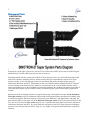
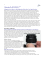
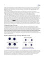
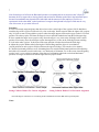
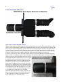
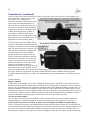
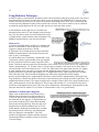
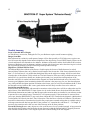
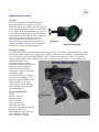
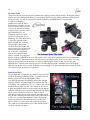
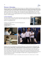
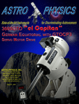
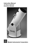
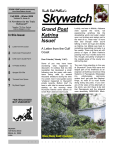
1
BINOTRON-27
Owner's Manual
2
2.Table
of Contents
3. Diagram of Parts
4. Eyepiece Holder Diagram
5. CollitronTM Rings and Collimation Without a Telescope
6. Collimation Without a Telescope ctd, Collimation With a Telescope
7. Collimation With a Telescope/ Field Chart
8. Collitron Ring Tightening Tool, The Power x Switch
9. Newtonian Telescopes
10. Newtonian Telescopes ctd
11 .Refractor Telescopes
12. Refractor Telescopes ctd
13. SCT Telescopes
14. Optional Accessories: OCS-A45, Eyepieces
15. Optional Accessories: Filter Switch, Filters
16. Warranty and Contact Information
3
Diagram of Parts
The BINOTRON-27 Super System has been designed to focus at three magnifications in virtually any telescope
designed for typical single eyepiece use. Not only is focus achieved, but three powers are accessible using the
patented Power x Switch while using only one pair of eyepieces.
Becoming familiar with the various parts of the B-27 Super System will be very useful and allow smooth and
trouble free operation. Obtaining focus in various telescope designs is dependent on using the B-27 Super
System correctly. In the following pages, there are descriptions and pictures detailing proper usage for
Newtonians, Refractors and SCTs. Importantly, become very familiar with the diagram of the B-27 Collitron
Eyepiece holders on the following page. Otherwise, incorrect parts of the eyepiece holder assembly will be
turned at night during use in the field and this will become frustrating. By spending time indoors in the light of
your home and using the eyepiece holders correctly, misidentifying the eyepiece holder parts at night can be
avoided.
TM
Referring to the above diagram, all parts are required when using a Newtonian Telescope. See the Newtonian
Telescopes Section for specific instructions. When using a Refractor and other scopes that work similarly such
as classical cassegrains, Mewlons, Planewave Telescopes, some Maksutovs, and many Ritchey Chretians, the
parts labled D and E are not used. refer to the Refractor Telescopes section. In SCTs, the parts labeled D, E and
F are not used so refer to the SCT section. Specific use is explained with more detail in each of the sections on
Newtonians, Refractors and SCTs. So, please learn how to properly use the B-27 Super System by reading the
sections on any telescope that you will be using. It is very simple, as long as the brief instructions are properly
followed.
4
Eyepiece Holder Parts and Use
The patent pending CollitronTM equipped eyepiece holders are a Denkmeier innovation that we are very excited
about. The Binoviewer can be collimated in a minute or less and very easily using this feature. This is thoroughly
explained in the page following this one.
However, the Collitron Ring is not the only feature that is special about the B-27 eyepiece holder. The diopter
rings on each eyepiece holder allow the user to obtain a very sharp focus for individual eyes. Therefore, those
without perfect 20/20 vision can adjust focus for both the right and left eye while viewing through their B-27
Binoviewer System. In fact, these new focusing mechanism do not rotate the eyepiece. The eyepiece moves up
and down in a very smooth motion. The focus adjustment has been set to an ideal speed as well. A change is
easily observed, but the motion is still considered to be "micro".
Loading the Eyepieces
The top "Eyepiece Locking Ring" (EPLR) allows the eyepiece to be inserted smoothly by turning this uppermost
ring counter-clockwise and removing the Dust Plugs. This allows an internal self centering split ring to expand.
Once the eyepiece barrel is fully inserted, the Locking Ring is then turned clockwise until the eyepiece is held
securely. Over tightening is not necessary but the ring should be turned to a point where it is nicely fingertightened.
Focusing Individual Eyepieces
Now, the diopters should be turned upward but only
slightly by rotating the Diopter Ring
Clockwise. If both Diopters are moved upward so
that perhaps the second white gradient line below the
+ sign is showing, each diopter may now be used at
the telescope and be moved both up and down for
sharp individual focus in each eye. Each person's
eyes may focus differently so the individual using the
B-27 will want to take note of where the diopters are
set for best focus so that this can be quickly readied
for each observing session.
Note: It is our opinion that focus should be monitored
and adjusted as needed during a nights' observing.
Rather than assuming one is in perfect focus, we have
found that it is essential to check focus of each
eyepiece periodically as sky conditions change and
the scope is moved to different locations of the sky
throughout the night. Viewing in proper and sharpest
focus is too important to ignore or leave to chance. It
is our recommendation that you use the focusing feature of the B-27 as often as you feel necessary! Even when
viewing with single eyepieces, one should be checking focus frequently. The same holds true for viewing with
the B-27 Super System.
Do Not Over-Tighten The Diopter Ring
It is recommended that the eyepiece barrel be fully inserted into the eyepiece holder initially with the diopter
fully bottomed out (turned clockwise). However, it is not necessary nor advisable to bottom out the diopter too
tightly. Over-tightening the diopter mechanism when turning counter-clockwise after it bottoms out can
then make it hard to free when turning clock-wise, and the lower Collitron Ring may then also become
loosened unintentionally and eyepiece holder collimation will have to be performed again. This is only
somewhat inconvenient though and can be quickly taken care of by using the Collitron Rings to collimate the
BINOTRON-27. You will find that this is a fast and simple process, and even enjoyable to many. (see pages 4-6)
5
Collimating The BINOTRON-27TM
Collimation is Easy! Below is a Brief Explanation Followed by a Very Simple Procedure.
Many Telescope users become nervous when faced with the prospect of collimating an optical instrument.
However, this is required if optimum performance and aberration-free images are to be obtained. Generally
speaking, telescope components such as mirrors and lenses must not be tilted or shifted from an ideal
relationship to one another or aberrations in the focused and defocused image will be seen. In the case of a
binoviewer, when we are referring to "collimation", we are actually dealing with alignment of the left and right
eyepieces so that they form a single image when merged. An object seen in the left eyepiece field at a certain
location should be seen at the same location in the right eyepiece. So we are not dealing with tilting optics or
aberrations, because a poorly aligned binoviewer will generally not introduce aberrations, only a "double
image". This poorly merged double vision results when the target object such as a planet or star is located in
different areas in each eyepiece field.
In order to move the object to the same exact area in each eyepiece field, we move the eyepiece holders, not the
object! The Collitron Eyepiece Holders have been designed to shift in a 360 degree direction on a flat plane.
Note that we at Denkmeier "set" the prisms first, and the fixtures hold these prisms in place permanently. The
Final Collimation using the Collitron Holders can be fined-tuned so that even the highest power images are in
the same location in each eyepiece field. Once this is done, the binoviewer will give extremely relaxed, two-eye
views at all magnifications. Collimation will become so quick and easy, that it may be repeated as often as you
feel the need. We even feel that the Collitron System makes this process enjoyable.
Preforming Collimation
Load your eyepieces into the holders first before loosening The Collitron Rings. See preceding page.
The diagram at the right illustrates how the Collitron Ring is loosened. It should be rotated counter-clockwise to
a point where the black parts above the Collitron Ring can be grasped and the entire holder may be shifted in any
directions. Do not over-loosen the Collitron Ring. The goal is to loosen it only enough so that both the right and
left holders can be moved in any direction in a flat plane. If
the Collitron Ring is loosened to much, the eyepiece holder
can tilt. The Collitron Ring must only be loosened enough
so that the eyepiece holder can slide in all directions in a
flat plane. You are now ready to collimate.
Without a Telescope
Firstly, we will offer a very simple and excellent
collimation method. Our B-27 Optical Collimation Device
is available as an option so that your Binotron-27 may be
collimated at anytime, indoors, without a telescope. This
device threads into the bottom of the Binoviewer or Power
x Switch and a beautiful in-focus target can be seen in both
eyepiece fields. It contains a fully coated optical lens, and a
laser engraved target. A separate instruction sheet is
provided.
Simple and Fast Procedure
1.Load eyepieces into the binoviewer eyepiece holders by following the instructions on page 4.
2. Thread the B-27 Optical Collimation Device into the bottom of the Binoviewer Power x Switch
3. View the target by looking through the eyepieces and facing a light source.
4. Make sure the target is in sharp focus for each eye. Consult B-27 Collimator instruction sheet.
5. Loosen each Collitron Ring a bit so that the Upper sections of the eyepiece holder can be shifted. A small
6
amount of friction should be present when shifting the holder. Note: The range of motion of the holder is quite
limited but a small amount of movement goes a long way in relocating an image seen in the eyepiece field.
Recap: Loosen the Collitron Rings just enough so that the eyepiece holders slide ( but do not tilt) a small
amount in any direction.
6. View the B-27 Collimation target while sliding one or both holders in a flat plane. You will notice
that the B-27 Collimation target becomes double, and very uncomfortable to observe with two eyes, and then
merges and becomes one single image that is comfortable to observe as the holders are shifted.
7. When the image becomes very comfortable to view, tighten one Collitron Ring down firmly.
8. Now, while looking through the binoviewer with both eyes, close one eye and view the target carefully with
the other eye. While viewing the target, observe an area of the image carefully and now open the closed eye so
that you are using both eyes. Did you notice a double image of that target area that quickly came together as a
single image after a very short delay? If so, slightly shift the holder with the still-loosened Collitron ring in very
small increments. Test again by repeating the one-eye blink method. You will quickly obtain an ideal holder
position and there will be no delay in achieving a perfectly merged single image with both eyes. This process
should take minutes or less once you become accustomed to the process. Once you have found this position,
tighten down the remaining loose Collitron Ring. Check things again using the same blink method. After a few
times, this process will become easy, rewarding and fun! You will have mastered BINOTRON-27 Collimation.
Collimation Using a Telescope
The same method outlined above can be used in a telescope. Rather than using the optional B-27 Optical
Collimation device, just focus on a planet or star field in your telescope. Carry out the same procedures as
described above, only the object viewed in your telescope will be your target. While collimating on astronomical
objects using your telescope at night works well, it may be easier if your telescope can focus on convenient
terrestrial targets in the daytime since they do not move and you are working with the holders in bright daylight.
In fact, we will outline a very objective method to test collimation in daylight using a telescope below. It should
be done in daytime using a fixed target. Of course, very large telescopes may not be able to find terrestrial
targets to focus on. In those cases, collimate while viewing astronomical objects, or purchasing the optional B-27
Optical Collimation Device .
Daytime Collimation Using a Telescope (Refractor or SCT)
Setting Vertical Target Location
Setting Horizontal Target Location
The main goal when collimating is to achieve a very comfortable strain-free view while using both eyesin your
binoviewer. If a very objective, but somewhat more time consuming method collimation is preferred, we outline
the following procedure . Once the Horizontal and Vertical positions of a target become identical in both the
right and left eyepieces, collimation may be considered to be of a very high order and can be objectively
measured. Please refer to the diagram above. The Procedure is outlined on the next page.
7
Note: Some degree of offset in the Horizontal position is acceptable and can even increase the 3-D perception
that many obsrvers report when viewing planets and star clusters! Whether such offset in the horizontal aspect
becomes uncomfortable may depend on the individual and the amount of offset employed. Feel free to
experiment! On the other hand, vertical positions of a target in the right and left eyepiece field must be very
close if not exact, or eye strain will occur.
Procedure
1. Focus on a nearby target and place that object close to the vertical edge of the eyepiece field. It should not
touch the edge of the eyepiece field but be very close to the edge. Set the target in either the right or left eyepiece
only. It is best to start viewing with the eyepiece where the target appears closest to the upper vertical 12 o'clock
position. The other eyepiece will show the target in a lower position further down from the fields upper edge.
2. Now examine the target in one eyepiece only where the target is very close to the field edge in the vertical
position. If necessary, move the telescope to place the target there, as close to the field edge but not touching.
3. Look in the other eyepiece. Is the object in the same position or further down from the field edge?
4. Adjust the eyepiece holders after loosening the Collitron Rings until the object is in an identical
vertical positions in each eyepiece field in relation to the upper field edge. This can take a few minutes.
5. Check the horizontal position as well. Alternating between vertical and horizontal positions while adjusting
the holder will eventually result in achieving a very high order of alignment. Yes, it takes some time and getting
used to, but it is a very objective measure of the degree of collimation when both vertical and horizontal
positions of a target are identical in both the right and left eyepiece fields!
Setting Collitron Holders For Vertical Alignment
Setting Collitron Holders For Horizontal Alignment
Print This Page as a Reference to Use During Actual Collimation Procedure With Telescope In Daytime
Notes:
8
Collitron Ring Tightening Tool
We provide a tool that allows the user to tighten the
Collitron Ring if they feel that finger pressure is not
adequate. This is generally unnecessary but since the
amount of "finger strength" will vary from person
to person, we felt that including a tool was probably a
good idea. The Collitron Ring features three holes
so that at least one can easily be accessed no matter
where the Collitron Ring ends up in rotation after it is
finger tightened. Please do not over tighten the
Collitron Ring! The ring should only be tightened to
the point where it will not become loosened while
operating the upper black rings used for locking and
unlocking the eyepiece and adjusting individual focus
(see page 3).
The Power x SwitchTM
The Dual Arm Power x Switch is our patented device invented by Russell Lederman of Denkmeier Optical.
It functions in various ways, depending on the telescope type being used. The three magnification factors
produced are different depending on the
telescope. This is explained in more detail in the
sections labeled Newtonian, Refractor and SCT
use. The name "Power x Switch" is actually
verbalized without the "x". We needed to add
the "x" for trademark purposes. A fully coated
optical doublet is housed in each carrier arm
(two arms). So there is a low power mode, a
mid power, and a high power mode. The low
power lens is always housed in the lens carrier
installed on the Logo-Side of the Power x
Switch Body. The non-Logo side contains the
highest power lens. The Mid-Power is achieved
with both Power x Switch arms in the out
position. Only one arm can be moved inward
into the light path at a time, and should be moved in
completely, until travel terminates.
The illustration at lower right shows the low
power arm on the Logo-Side fully inserted into
the light path of the binoviewer. The
magnifications that result are indicated in the
photo. These magnification factors are
multiples of what a single eyepiece would
produce. Ex: If an eyepiece renders 100X when
used as a single eyepiece, it will produce 130X
when used in the B-27 Super System with the
Low Power Arm moved to "IN" , when a
Newtonian or Refractor is used. It will produce
only 66X when used in an SCT. This is
explained in more detail later in this manual.
9
Using Newtonian Telescopes
Please refer to the Parts Diagram on page 2.
The B-27 Super System is shipped in the case fully assembled and ready for use in Newtonian Telescopes. What
you will receive is shown above. Note that the illustration also shows the B-27 with optional D21 Eyepieces. The
D21 Eyepieces are not included unless you have ordered them. The Super System Assembly consisting of Power
x Switch, 2" Part O Nosepiece, Middle Newtonian Spacer with Silver Lock Ring, and finally the Multi-Purpose
OCS Cell must be inserted fully into your focuser until the Power X Switch is flush with your focuser drawtube.
1.Now, the Lower Power Arm is pushed in. Rack your focuser drawtube in until focus is achieved.
2. If focus is not achieved, remove the entire assembly from the telescope and thread out the Middle Newtonian
Spacer and Silver Lock Ring from the 2" Part O Nosepiece. The Silver Lock Ring may be a bit tight. Unthread it
counter-clockwise to allow the Middle Newtonian Spacer
to be lengthened outward (unthreaded). Try to focus again
by sliding the entire system back into the focuser until
flush. Remember that the Low Power Mode requires the
most in-travel of your focuser. The Middle Newtonian
Spacer must be lengthened until you can rack inward just
past focus. It is important to be able to go inward past the
focus point, and then outward to a perfect focus in order to
be sure that perfect focus has been achieved. Every scope
is a bit different which is why the Middle Spacer's ability
to be lengthened is so important. Once the Middle
Newtonian Spacer has been set properly, the Silver Lock
Ring can be threaded back downward until flush with the
2" Part O Nosepiece. If focus is not achieved in Low
Power Mode, please see "Troubleshooting".
10
Newtonian Use (continued)
Once Low power Focus has been achieved, the next is mid power. Move the Low Power Arm completely out.
Now both Power x Switch arms are in the
out position. This is mid power in
Newtonian Telescopes. You must rack your
focuser draw tube outward until focus is
achieved. This is considered by many to be
the ideal power mode for observing planets.
Only the front OCS Lens is being used now
to bring focus through the B-27 Body to
your eyepieces. While all of the Power x
Switch optics are of very high quality, many
believe that the fewer optics there are in the
light path, the better the image quality.
The next power mode is the highest. This is
achieved when the arm on the non-logo side
of the Power x Switch is moved into the light
path. This requires the most out travel. If you
rack your focuser drawtube completely out
and still do not achieve focus (which is
possible with many low profile focusers),
loosen your drawtube thumbscrew and pull
the binoviewer assembly out a bit until you
achieve focus and then go outward a slight
amount past that point. The 2" tubes of the
Super System Assembly provide an
abundance of contact area allowing this to be
done without any issues. Hopefully, you can
still rack inward and achieve low power focus when pushing in the logo side arm. It is possible that with some
telescopes, all three focus positions will not be reached without the need to withdraw the Super System
Assembly outward in highest power mode. This depends on how the Newtonian mirrors, and focuser have been
spaced.
Trouble Shooting
Images seem poor:
In the unlikely event that this occurs, check collimation of the telescope. with the B-27 Super System in place.
Diffraction patterns should be unchanged when using the B-27 Super System as compared to a single eyepiece.
However, the scope should have the collimation fine tuned using a stellar diffraction pattern in certain cases, for
optimal performance. This may be caused by focuser drop due to the weight of the B-27 Super System. In fact,
many observers choose to re-check collimation when the scope is pointed at various areas of the sky! It is always
a good idea to be able to examine a diffraction pattern and fine tune the Primary Mirror collimation so that the
airy disc of the diffraction pattern appears at dead center as focus is closed down to a point.
Do I need a counterweight?
Yes, very likely. Any heavy accessory should be counter weighed. There are so many methods that one can
employ and there is a wealth of information on the internet to help you decide which one is best for you.
I can't reach focus in Low Power Mode no matter how far I lengthen the Middle Newtonian Spacer.
Call us. We can provide a spacer cell that threads between the Newtonian spacer and the OCS Cell and this will
solve the problem and allow the Newtonian Spacer to be also be closed back down a bit. Another alternative is to
move your primary mirror collimation bolts higher, pushing the mirror a bit closer to the secondary mirror. A
third alternative requires your truss poles to be trimmed slightly. In solid tubes, the mirror cell can be moved up.
11
Using Refractor Telescopes
In order to achieve a focused image, Refractors require optical assistance when using a binoviewer. Our Power x
Switch and Optical Corrector System (OCS) allow focus to be obtained. The BINOTRON-27 Super System
must be used correctly for focus to be achieved. We outline the methods below. There are a few refractors that
were/are specially shortened in order to allow a binoviewer to focus. These can be made to work in a different
way than the typical Refractor. We will cover this special case at the end of this section.
In the illustration on the right, the OCS Cell has been
threaded into the end of a 2" star diagonal on the telescope
side. This now allows focus to occur when the binoviewer
is loaded into the eyepiece holder of the star diagonal. The
Middle Newtonian Spacer is not used for refractors.
Refractor Use
1. Remove the Middle Spacer with Silver Lock Ring and
the OCS Cell from the 2" Part O Nosepiece. The Part O
Nosepiece remains in the Power x Switch.
2. Thread the OCS Cell that has been removed from the
Middle Newtonian Spacer Tube into the telescope-side
tube of your 2" star diagonal.
3. Load the Binoviewer with Power x Switch and 2" Part
O Nosepiece into the eyepiece holder of the star diagonal.
4. Now, push in the Low Power Arm (Logo-Side) of the
Power x Switch. In order to reach focus, the drawtube of the refractor must be racked inward. The magnification
factor is approximately 1.3X. In other words, if a single eyepiece produces 30X when used in mono-mode, it
will now produce 39X in the binoviewer or 1.3x30x=39x. These figures are approximate and can vary slightly.
5. After obtaining focus, move the Low Power Arm out. With both arms of the Power x Switch in the out
position, mid power results with approximately a 2.3X magnification factor. Again using the above example,
69X will be the result. Various brands of Diagonals may affect these magnification factors slightly.
6. Now, the final highest power magnification of the Power x Switch can be implemented by moving the NonLogo Side Power x Switch arm inward. The focuser of the refractor must be racked outward to reach focus. The
magnification factor becomes 3X or again, using the above example results in 90X. Note: many Refractors have
only a small amount of overall draw tube travel. Those scopes with less than 3.5" of overall travel may fail to
reach focus in the highest power mode. This issue can be eliminated by withdrawing the star diagonal from the
telescope until focus is reached. Use of a short 2" extension tube is also a very good remedy.
Denkmeier or William Optics Diagonals
When using our Denkmeier Optical Diagonal or a
William Optics Diagonal, the position of the OCS
Cell can be placed closer to the diagonal mirror. In
the illustration on the right, the 2" diagonal tube has
been removed and the OCS Cell has been threaded
directly into the diagonal body. Then the removed 2"
diagonal tube has been threaded into the OCS Cell
female threads. All threads are 48mm male or female.
By placing the OCS cell directly onto the diagonal
body, two things are accomplished - The focus
position is brought more inward toward the telescope,
and the magnification is slightly lowered in all Power
x Switch settings.
12
Trouble Shooting
Scope is Unstable Due to Weight
As with all heavy accessories, adding the B-27 to your Refractor requires careful counter-weighing.
Images Seem Dim
Most refractors have relatively small aperture. Images will be dim especially at 3X if high power eyepieces are
used. Of course this depends on the intrinsic brightness of the object being viewed. While deepsky objects can be
viewed satisfactorily, this depends on sky darkness, brightness of the target, and the focal length of the eyepieces
being used. Refractors excel on planetary and lunar viewing with a binoviewer unless the observing site is a dark
one. Expectations should be realistic when using a small aperture telescope.
High Power 3X Mode Will Not Focus
The Mid and High Power Modes of the Power x Switch require the focuser of the Refractor to be racked
outward. Many refractors have only a limited overall length of the focuser tube. If the focuser drawtube has less
than 3.5" of overall travel, it is possible that the highest and even the mid power settings will fail to reach focus
when the tube of the refractor is fully racked out. Two Inch Extension Tubes are widely available and some cost
under $20. It is a good idea to obtain one. Another quick remedy is to just pull the star diagonal out of the
drawtube until focus is reached, and then lock the diagonal in with the drawtube thumb screw. Be careful! You
must use good judgment when ascertaining whether this solution is the proper way for you. Note that refractors
vary widely and the focal plane position in relation to the focuser varies as well. Do not withdraw the B-27 from
the diagonal eyepiece holder as this is not a good solution and will likely not allow focus to be achieved.
Special Shortened Refractors
Some refractors have been made with removable extensions so that a binoviewer will focus without the need for
optical lenses. If the BINOTRON-27 Super System is to be used with the Power xSwitch and OCS then follow
the Refractor Instructions and make sure that the removable extension tubes are installed in your refractor so that
it operates like a conventional scope. Then the B-27 will operate properly. If the extensions are removed from
your scope, then the BINOTRON-27 may reach focus without the OCS installed in the diagonal. A third method
is to thread the OCS directly into the 2" Part O Nosepiece. Then the Power x Switch will function. The refractor
must still be shortened (no extension tubes) but this may require more outward racking than is available unless a
mid range extension tube has been provided. If not, purchase a 2" extension tube with about 2" - 3"of length. If
necessary, the extension can be slid in or out of the telescope to hit all focus positions.
Terrestrial Viewing-Because many objects are close to the observer, focus is pushed outward . A long extension
tube should be placed in the telescope before the star diagonal so that the diagonal and B-27 Super System can
slide outward as needed. Rule: Close Targets require more outward sliding of the star diagonal.
13
SCT TELECOPES
Schmidt Cassegrain Telescopes are very versatile and the BINOTRON-27 Super System works in a very
different way. The typical SCT has a moving primary mirror. As it is moved toward the secondary mirror
mounted on the front corrector plate, focus is pushed out of the rear of the optical tube. This provides a great
amount of "back focus". Therefore, the OCS cell is not used, or required. In fact, the focus is moved so far
outward, that the Power x Switch can produce true focal reduction when the Low Power Arm is pushed in. This
is very important because the typical F/10 ratio of an 8", 9.25", 10" or larger SCT produces a very large image
scale. The ability to implement focal reduction changes this F/10 to approximately an F/6.6 ratio. This makes
deepsky objects more compact due to lower power. The object becomes easier to see. The Mid Power setting
increases the focal ratio a bit. The Power Factor is about 1.15X and this is due to the interaction of the primary
mirror with the telenegative secondary mirror. The highest power mode becomes approximately 2X since no
OCS Cell is being used.
SCT Use
1. Remove the Middle Newtonian Spacer with Silver
Lock Ring and the OCS Cell. These are not used in
an SCT. The illustration at right shows the
BIONTRON-27 ready to be used in an SCT.
2. Load the unit into your 2" Star Diagonal. Note: An
optional 1.25" nosepiece is available for 1.25"
diagonal use, though use of a 2" diagonal is more
stable and recommended.
3. Start with both Power x Switch Arms in the OUT
position as pictured at right. This is the mid power
mode. Point the scope to a bright object to start.
4. The focuser knob of your SCT Scope must be
turned counter-clockwise until focus is achieved. It
will likely require many turns and this will vary from
scope to scope.
5. Once focus in Mid Power Position is reached, move the Logo-Side Low Power Arm inward. This is the Focal
Reduction Mode and produces approximately F/6.6. In other words, if a single eyepiece produces 50X, this
reduction mode will produce 33X. Several turns of the focuser from the Mid Power Position in a counterclockwise rotation will be required to reach focus.
6. It is always advised that when leaving the Reduction Mode, move the Reduction Arm out and once again
focus in Mid Power Mode. This requires several clockwise turns of the focuser knob of your SCT. One focus is
achieved in Mid Power, move the Non-Logo-Side Arm in. This is High Power Mode and produces a 2X factor.
A 50X power eyepiece used singly, will operate at 100X. in the B-27. The focuser knob must be rotating
Clockwise from the point where mid-power focus was.
Trouble Shooting
I cannot reach focus in Reduction Mode.
Most SCTs reach focus. If you run out of counter-clockwise turns when trying to focus in reduction mode, we
can provide solutions. We are currently designing a special SCT right angle prism diagonal that has the shortest
possible light path and will reduce the back focus requirements so that focus in reduction mode will not be a
problem. It will be available soon. We also have other solutions available at this time. Call for more information.
Images are not as sharp as hoped
All SCT Owners should become very familiar with collimating the secondary mirror of their telescope. This is a
must of the best optical images are to be obtained with both single eyepieces as well as the BINOTRON-27. It is
recommended that one collimate the secondary mirror with the BINOTRON-27. A star can be centered and
viewed with both eyes, and the secondary mirror can be collimated in the same way as when using a single
eyepiece. The views will be very sharp if care is taken to do this.
14
Optional Accessories
OCS-A45
The OCS Cell shipped with all BINOTRON-27
Super Systems has a clear aperture of 37mm.
Pictured at right is the new OCS-A45. This optic has
a clear aperture of 45mm, the largest we could make
in a 2" format. It can better handle the outer rays of
a converging beam produced by a telescope mirror
and this means better illumination. We recommend
it for any telescope faster than F/5 and we also
believe that the benefit of using this may be
observable in slower telescopes. Super Optical
Quality, Fully Multi-Coated of course! Each lens is
tested in our NY Facilty before being passed.
Denkmeier Eyepieces
Our Denkmeier Eyepieces are world renowned and for good reason - The glass used is high index, the coatings
are the best, and the performance is exquisite. No, the D21s and D14s are not inexpensive. But remember that
any pair of eyepieces used in the BINOTRON-27 Super System becomes three pairs! This is because they
operate at three magnifications. When given the choice of using an average eyepiece pair, or a fantastic pair,
consider that the pair used
essentially triples in operation.
Available in 21mm and 14mm focal
length, they sport 65 degrees of
AFOV and provide amazing
performance on planets, The Moon,
and deepsky objects.
Our D21s and D14s are as light as
we can possibly make them. The
barrels are anodized aluminum, not
chrome plated brass in order to
reduce weight. Consider adding a
pair of our D21s, D14s, or both to
your BINOTRON-27
Eyepiece Specifications
Weight
D21 8oz D14 9oz
Eye Relief 20mm
AFOV 65 Degrees
Color Corrected: Yes
High Index Glass: Yes
All Lenses Fully Multi-Coated: Yes
Matched and Tested: Yes
Rotating Batwing Eyeguards: Yes
D21: 6 Elements, 4 Groups
D14: 6 Elements, 5 Groups
D21 Eyepieces in BINOTRON-27 Equipped With Optional Filter Switch
15
The Filter Switch
Using filters in your telescope can greatly enhance the visibility of many deepsky objects. Being able to move
filters in and out of the light path quickly is a great thing! That is precisely what our Denkmeier Filter Switch
allows you to do. So, why not add our Filter Switch System to your BIONTRON-27 Super System.
In addition to changing
magnifications with the Super
System Power x Switch, you can
also move filters in and out of the
view at will, without ever having
to pull your two eyes away from
your BINOTRON-27. At
Denkmeier Optical, we pride
ourselves on the quality of our
machining. The Filter Slides move
in out of the light path with a
buttery smooth feel. There are
three possible Filter Switch
positions; No Filter, Right Filter,
and Left Filter. You can easily slip
each carrier loaded with a filter
out of the Filter Switch Body
without tools, then load other
filters in seconds. It is suggested
that you equip every filter that you own with a carrier so it is ready to be loaded into the Filter Switch Module.
We even make 1.25" Step Down carriers that will carry our optional planetary filter or most other 1.25" filters.
While the Filter Switch can be added later, it is best to add this option at the time that you purchase your
BINOTRON-27 Super System to avoid extra cost. The Filter Switch option is reasonably priced, and a great
addition! Our carriers accept virtually all brands of filters though we do recommend that you consider our Denk
Hi-Def Filters if you do not already own filters.
Denk Hi-Def Filters
Did you know that we make our own filters? Using our on-site
Ion Beam Sputtering Technology (IBS) , we produce our own
brand of world class Nebula and Planetary filters.
Our OIII Filter performs exceptionally on emission Nebulae,
Planetary Nebulae, and many super Nova remnants like The
Veil Nebula, and is available in 1.25" or 2" format. With a wider
bandpass than the OIII, our UHC Filter allows the H-b line to
transmit and performs better on some deepsky objects than the
OIII. One of the above does not make the other obsolete though.
We do suggest reading up on filter use. There is a lot of
information out there that is useful to know and some objects
are seen better with the OIII while others better lend themselves
to UHC use. Our Dual Band Planetary Filter will bring out
features on planet discs that may otherwise be difficult to
observe. Please visit our website and read about our filters.
They make an excellent addition to the Filter Switch Option if
you do not already own filters.
16
Warranty Information
We will fix or replace your BINOTRON-27 Super System or any additional optional accessory purchased from
Denkmeier Optical, Inc. or an authorized Denkmeier Dealer for a period of one year after delivery. This warranty
covers any failure of the system or optics due to faulty manufacturing or damage incurred during normal use due
to parts failure. While we are always willing to repair systems due to accidental dropping or other circumstances
beyond our control, this type of damage is not covered under the warranty. Shipping charges may also apply.
This warranty does not cover any product that was purchased second hand whether through a dealer or a private
party. This warranty covers the original purchaser only. It is strongly recommended that you retain your original
receipt as a record of purchase.
Contact Information
We can be reached toll-free at 866-340-4578. This may not work outside of the
USA. We can also be reached by dialing 410-208-6014. If dialing from outside
of the USA, our country code is 01.
Email us at [email protected]
Denkmeier Optical Headquarters are located in Hauppauge, NY.
Our Shipping Address:
Denkmeier/Spectrum Thin Films
135 Marcus Blvd
Hauppauge, NY 11788
Denkmeier Optical Workers
SpectrumThin Films Coating Lab Area
Tony Pirera, Ted Haucher and Russ Lederman at NEAF, 2012
Denkmeier Optical, Inc. Headquarters are located in Hauppauge, NY. We joined forces with Spectrum Thin
Films 4 years ago, making the move to their headquarters on Long Island in New York. Originally, Spectrum
Thin Films coated our optics before we decided to team up. Denkmeier Optical, Inc. is co-owned by Anthony
Pirera and Denkmeier Optical Founder Russ Lederman, inventor of the Optical Corrector System, Power x
Switch, and Power Switch Star Diagonals. Our workers are experienced in handling optics of all kinds under
clean room conditions. Various types of optical coatings are done on premises for professional observatories,
NASA, and other clients. The benefit of teaming up with Spectrum Thin Films has enabled Denkmeier Optical to
innovate and bring new products to the marketplace. The future looks very bright. Keep looking for new
products in the next few years!
Copyright, 2013 Denkmeier Optical, Inc. All rights reserved. Reproduction without written permission from Denkmeier Optical, Inc. is Prohibited.