1
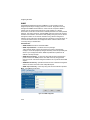
MANAGEMENT GUIDE
SMCGS8P-Smart
EZ SwitchTM 10/100/1000
8-Port Web Smart Switch with PoE
EZ Switch 10/100/1000
Installation Guide
From SMC’s EZ line of feature-rich workgroup LAN solutions
20 Mason
Irvine, CA 92618
Phone: (949) 679-8000
July 2007
Pub. # 150000022900H
E072007-DT-R02
Information furnished by SMC Networks, Inc. (SMC) is believed to be accurate and
reliable. However, no responsibility is assumed by SMC for its use, nor for any
infringements of patents or other rights of third parties which may result from its use. No
license is granted by implication or otherwise under any patent or patent rights of SMC.
SMC reserves the right to change specifications at any time without notice.
Copyright © 2007 by
SMC Networks, Inc.
20 Mason
Irvine, CA 92618
All rights reserved. Printed in Taiwan
Trademarks:
SMC is a registered trademark; and EZ Switch, TigerStack and TigerSwitch are
trademarks of SMC Networks, Inc. Other product and company names are trademarks or
registered trademarks of their respective holders.
Limited Warranty
Limited Warranty Statement: SMC Networks, Inc. (“SMC”) warrants its products to be
free from defects in workmanship and materials, under normal use and service, for the
applicable warranty term. All SMC products carry a standard 90-day limited warranty from
the date of purchase from SMC or its Authorized Reseller. SMC may, at its own discretion,
repair or replace any product not operating as warranted with a similar or functionally
equivalent product, during the applicable warranty term. SMC will endeavor to repair or
replace any product returned under warranty within 30 days of receipt of the product.
The standard limited warranty can be upgraded to a Limited Lifetime* warranty by
registering new products within 30 days of purchase from SMC or its Authorized Reseller.
Registration can be accomplished via the enclosed product registration card or online via
the SMC Web site. Failure to register will not affect the standard limited warranty. The
Limited Lifetime warranty covers a product during the Life of that Product, which is
defined as the period of time during which the product is an “Active” SMC product. A
product is considered to be “Active” while it is listed on the current SMC price list. As new
technologies emerge, older technologies become obsolete and SMC will, at its discretion,
replace an older product in its product line with one that incorporates these newer
technologies. At that point, the obsolete product is discontinued and is no longer an
“Active” SMC product. A list of discontinued products with their respective dates of
discontinuance can be found at:
http://www.smc.com/index.cfm?action=customer_service_warranty.
All products that are replaced become the property of SMC. Replacement products may
be either new or reconditioned. Any replaced or repaired product carries either a 30-day
limited warranty or the remainder of the initial warranty, whichever is longer. SMC is not
responsible for any custom software or firmware, configuration information, or memory
data of Customer contained in, stored on, or integrated with any products returned to
SMC pursuant to any warranty. Products returned to SMC should have any
customer-installed accessory or add-on components, such as expansion modules,
removed prior to returning the product for replacement. SMC is not responsible for these
items if they are returned with the product.
Customers must contact SMC for a Return Material Authorization number prior to
returning any product to SMC. Proof of purchase may be required. Any product returned
to SMC without a valid Return Material Authorization (RMA) number clearly marked on
the outside of the package will be returned to customer at customer’s expense. For
warranty claims within North America, please call our toll-free customer support number
at (800) 762-4968. Customers are responsible for all shipping charges from their facility to
SMC. SMC is responsible for return shipping charges from SMC to customer.
WARRANTIES EXCLUSIVE: IF AN SMC PRODUCT DOES NOT OPERATE AS
WARRANTED ABOVE, CUSTOMER’S SOLE REMEDY SHALL BE REPAIR OR
REPLACEMENT OF THE PRODUCT IN QUESTION, AT SMC’S OPTION. THE
FOREGOING WARRANTIES AND REMEDIES ARE EXCLUSIVE AND ARE IN LIEU OF
ALL OTHER WARRANTIES OR CONDITIONS, EXPRESS OR IMPLIED, EITHER IN
FACT OR BY OPERATION OF LAW, STATUTORY OR OTHERWISE, INCLUDING
WARRANTIES OR CONDITIONS OF MERCHANTABILITY AND FITNESS FOR A
PARTICULAR PURPOSE. SMC NEITHER ASSUMES NOR AUTHORIZES ANY OTHER
PERSON TO ASSUME FOR IT ANY OTHER LIABILITY IN CONNECTION WITH THE
SALE, INSTALLATION, MAINTENANCE OR USE OF ITS PRODUCTS. SMC SHALL
i
NOT BE LIABLE UNDER THIS WARRANTY IF ITS TESTING AND EXAMINATION
DISCLOSE THE ALLEGED DEFECT IN THE PRODUCT DOES NOT EXIST OR WAS
CAUSED BY CUSTOMER’S OR ANY THIRD PERSON’S MISUSE, NEGLECT,
IMPROPER INSTALLATION OR TESTING, UNAUTHORIZED ATTEMPTS TO REPAIR,
OR ANY OTHER CAUSE BEYOND THE RANGE OF THE INTENDED USE, OR BY
ACCIDENT, FIRE, LIGHTNING, OR OTHER HAZARD.
LIMITATION OF LIABILITY: IN NO EVENT, WHETHER BASED IN CONTRACT OR
TORT (INCLUDING NEGLIGENCE), SHALL SMC BE LIABLE FOR INCIDENTAL,
CONSEQUENTIAL, INDIRECT, SPECIAL, OR PUNITIVE DAMAGES OF ANY KIND, OR
FOR LOSS OF REVENUE, LOSS OF BUSINESS, OR OTHER FINANCIAL LOSS
ARISING OUT OF OR IN CONNECTION WITH THE SALE, INSTALLATION,
MAINTENANCE, USE, PERFORMANCE, FAILURE, OR INTERRUPTION OF ITS
PRODUCTS, EVEN IF SMC OR ITS AUTHORIZED RESELLER HAS BEEN ADVISED
OF THE POSSIBILITY OF SUCH DAMAGES.
SOME STATES DO NOT ALLOW THE EXCLUSION OF IMPLIED WARRANTIES OR
THE LIMITATION OF INCIDENTAL OR CONSEQUENTIAL DAMAGES FOR
CONSUMER PRODUCTS, SO THE ABOVE LIMITATIONS AND EXCLUSIONS MAY
NOT APPLY TO YOU. THIS WARRANTY GIVES YOU SPECIFIC LEGAL RIGHTS,
WHICH MAY VARY FROM STATE TO STATE. NOTHING IN THIS WARRANTY SHALL
BE TAKEN TO AFFECT YOUR STATUTORY RIGHTS.
* SMC will provide warranty service for one year following discontinuance from the active
SMC price list. Under the limited lifetime warranty, internal and external power supplies,
fans, and cables are covered by a standard one-year warranty from date of purchase.
SMC Networks, Inc.
20 Mason
Irvine, CA 92618
ii
Contents
Chapter 1: Introduction
Description of Software Features
1-1
1-1
Chapter 2: Initial Configuration
2-1
Chapter 3: Configuring the Switch
Using the Web Interface
Navigating the Web Browser Interface
Home Page
Configuration Options
Panel Display
Main Menu
Web Configuration
Displaying Status Overview
Showing Port Statistics
Displaying the System Name
Setting the Switch’s IP Address
Configuring the Logon Password
Tools
Register Product
Static MAC
Port Configuration
Storm Control
Port Mirroring
Cable Diagnostic
Trunk Membership
Trunk Configuration
Trunk Rate Limit
LACP Setup
LACP Status
VLAN Settings
802.1X
LLDP
LLDP Neighbor Table
SNMP
POE
Switch Power Status
3-1
3-1
3-1
3-1
3-2
3-3
3-3
3-5
3-5
3-8
3-10
3-11
3-12
3-12
3-15
3-15
3-15
3-16
3-17
3-18
3-19
3-20
3-21
3-21
3-22
3-23
3-25
3-28
3-29
3-30
3-31
3-31
iii
Contents
Appendix A: Software Specifications
Software Features
Management Features
Standards
Management Information Bases
A-1
A-1
A-2
A-2
A-2
Appendix B: Troubleshooting
Forgot or Lost Password
Changing a PC’s IP Address
C-1
C-1
C-1
iv
Tables
Tables
Table 3-1 Web Page Configuration Buttons
Table 3-2 Switch Main Menu
Table 3-3 Port Statistics
3-2
3-3
3-8
v
Tables
vi
Figures
Figures
Figure 3-2 Front Panel Indicators
Figure 3-3 Switch Information
Figure 3-4 Port Statistics
Figure 3-5 System Name
Figure 3-6 LAN Settings
Figure 3-7 Password Settings
Figure 3-8 Reset to Factory Defaults
Figure 3-9 Upgrade Firmware
Figure 3-10 Upload/Download Configuration
Figure 3-11 Restart Switch
Figure 3-12 Register Product
Figure 3-13 Port Configuration
Figure 3-14 Port Broadcast Control
Figure 3-15 Port Mirroring
Figure 3-16 Cable Diagnostics
Figure 3-17 Trunk Membership
Figure 3-18 Trunk Configuration
Figure 3-19 Trunk Rate Limiting
Figure 3-20 LACP Port Configuration
Figure 3-21 LACP Status Overview
Figure 3-22 VLAN Settings
Figure 3-23 802.1X Configuration
Figure 3-24 802.1X Statistics
Figure 3-27 SNMP Configuration
3-3
3-7
3-10
3-10
3-11
3-12
3-13
3-13
3-14
3-14
3-15
3-16
3-17
3-18
3-19
3-20
3-20
3-21
3-22
3-23
3-25
3-27
3-28
3-30
vii
Figures
viii
Chapter 1: Introduction
The EZ Switch 10/100/1000 SMCGS8P-Smart is a managed Gigabit PoE switch
that delivers performance and control to your network. It provides 8 full-duplex
1000BASE-T ports that significantly improve network performance and boost
throughput using features configured through a web-based management interface.
With 16 Gigabits of throughput bandwidth, this switch provides an effective solution
to meeting the growing demands on your network.
Description of Software Features
The switch provides a wide range of advanced performance enhancing features.
Flow control eliminates the loss of packets due to bottlenecks caused by port
saturation. Broadcast storm suppression prevents broadcast traffic storms from
engulfing the network. CoS priority queueing ensures the minimum delay for moving
real-time multimedia data across the network. While multicast filtering provides
support for real-time network applications. Some of the management features are
briefly described below.
Configuration Backup and Restore – You can save the current configuration
settings to a file on the web management station, and later download this file to
restore the switch configuration settings.
Authentication – The switch supports port-based user authentication via the IEEE
802.1X protocol. This protocol uses the Extensible Authentication Protocol over
LANs (EAPOL) to request user credentials from the 802.1X client, and then verifies
the client’s right to access the network via an authentication server.
Port Configuration – You can manually configure the speed, duplex mode, and
flow control used on specific ports, or use auto-negotiation to detect the connection
settings used by the attached device. Use the full-duplex mode on ports whenever
possible to double the throughput of switch connections. Flow control is enabled to
control network traffic during periods of congestion and prevent the loss of packets
when port buffer thresholds are exceeded. The switch supports flow control based
on the IEEE 802.3x standard.
Port Mirroring – The switch can unobtrusively mirror traffic from any port to a
monitor port. You can then attach a protocol analyzer or RMON probe to this port to
perform traffic analysis and verify connection integrity.
Port Trunking – Ports can be combined into an aggregate connection. Trunks can
be manually set up or dynamically configured using IEEE 802.3ad Link Aggregation
Control Protocol (LACP). The additional ports dramatically increase the throughput
across any connection, and provide redundancy by taking over the load if a port in
the trunk should fail. The switch supports up to 4 trunks.
Broadcast Storm Control – Broadcast suppression prevents broadcast traffic from
overwhelming the network. When enabled on a port, the level of broadcast traffic
1-1
Introduction
passing through the port is restricted. If broadcast traffic rises above a pre-defined
threshold, it will be throttled until the level falls back beneath the threshold.
Static Addresses – A static address can be assigned to a specific interface on this
switch. Static addresses are bound to the assigned interface and will not be moved.
When a static address is seen on another interface, the address will be ignored and
will not be written to the address table. Static addresses can be used to provide
network security by restricting access for a known host to a specific port.
IEEE 802.1D Bridge – The switch supports IEEE 802.1D transparent bridging. The
address table facilitates data switching by learning addresses, and then filtering or
forwarding traffic based on this information. The address table supports up to 8K
addresses.
Store-and-Forward Switching – The switch copies each frame into its memory
before forwarding them to another port. This ensures that all frames are a standard
Ethernet size and have been verified for accuracy with the cyclic redundancy check
(CRC). This prevents bad frames from entering the network and wasting bandwidth.
To avoid dropping frames on congested ports, the switch provides 400 KB for frame
buffering. This buffer can queue packets awaiting transmission on congested
networks.
Virtual LANs – The switch supports up to 64 VLANs. A Virtual LAN is a collection of
network nodes that share the same collision domain regardless of their physical
location or connection point in the network. The switch supports tagged VLANs
based on the IEEE 802.1Q standard. Ports can be manually assigned to a specific
set of VLANs. This allows the switch to restrict traffic to the VLAN groups to which a
user has been assigned. By segmenting your network into VLANs, you can:
• Eliminate broadcast storms which severely degrade performance in a flat network.
• Simplify network management for node changes/moves by remotely configuring
VLAN membership for any port, rather than having to manually change the
network connection.
• Provide data security by restricting all traffic to the originating VLAN.
Power-over-Ethernet (PoE) – The switch’s eight RJ-45 ports support the IEEE
802.3af PoE standard that enables DC power to be supplied to attached devices
over wire pairs in the connecting Ethernet cable. Any 802.3af compliant device
attached to a port can directly draw power from the switch over the Ethernet cable
without requiring its own separate power source. This capability gives network
administrators centralized power control for devices such as IP phones and wireless
access points, which translates into greater network availability.
A maximum PoE power budget for the switch (power available to all switch ports) is
defined so that power can be centrally managed, preventing overload conditions at
the power source. If the power demand from devices connected to the switch
exceeds the power budget, the switch uses port power priority settings to limit the
supplied power.
1-2
Chapter 2: Initial Configuration
To make use of the management features of your EZ Switch, you must first
configure it with an IP address that is compatible with the network it is being installed
in. This should be done before you permanently install the switch in the network.
Follow this procedure:
1.
Place your EZ Switch close to the PC that you intend to use for configuration. It
helps if you can see the front panel of the switch while working on your PC.
2.
Connect the Ethernet port of your PC to any port on the front panel of your EZ
Switch. Connect power to the switch and verify that you have a link by checking
the front-panel LEDs.
3.
Check that your PC has an IP address on the same subnet as the switch. The
default IP address of the switch is 192.168.2.10 and the subnet mask is
255.255.255.0, so the PC and switch are on the same subnet if they both have
addresses that start 192.168.2.x. If the PC and switch are not on the same
subnet, you must manually set the PC’s IP address to 192.168.2.x (where “x” is
any number from 1 to 255, except 10). If you are unfamiliar with this process,
see “Changing a PC’s IP Address” on page 1-37.
4.
Open your web browser and enter the address http://192.168.2.10. If your PC is
properly configured, you will see the login page of your EZ Switch. If you do not
see the login page, repeat step 3.
5.
Enter the default password “smcadmin” and click on the Login button.
6.
From the menu, click on SYSTEM, then click on LAN Settings. On the LAN
Settings page, enter the new IP address, Subnet Mask and Gateway IP
Address for the switch, then click on the APPLY button.
No other configuration changes are required at this stage, but it is recommended
that you change the administrator’s password before logging out. To change the
password, click SYSTEM, Password, and then fill in all the fields on the Password
Settings page before clicking on the APPLY button.
2-1
Initial Configuration
2-2
Chapter 3: Configuring the Switch
Using the Web Interface
This switch provides an embedded HTTP web agent. Using a web browser you can
configure the switch and view statistics to monitor network activity. The web agent
can be accessed by any computer on the network using a standard web browser
(Internet Explorer 5.5 or above, or Mozilla Firefox 1.0 or above).
Prior to accessing the switch from a web browser, be sure you have first performed
the following tasks:
1.
Configure the switch with a valid IP address, subnet mask, and default gateway.
(Defaults: IP address 192.168.2.10; Subnet mask 255.255.255.0; Gateway
0.0.0.0)
2.
Set a new password using the web interface. (Default: “smcadmin”). Access to
the web interface is controlled by the password. See “Configuring the Logon
Password” on page 3-12.
Note: If you cannot remember the switch's IP address, you can restore the original
settings by following the procedure described in the “Troubleshooting” section.
Navigating the Web Browser Interface
To access the web-browser interface you must first enter a password. The user has
read/write access to all configuration parameters and statistics. The default
password for the switch is “smcadmin.”
Note: If user input is not detected within five minutes, the current session is terminated.
Home Page
When your web browser connects with the switch’s web agent, the home page is
displayed as shown below. The home page displays the Main Menu on the left side
of the screen and System Information on the right side. The Main Menu links are
used to navigate to other menus, and display configuration parameters and
statistics.
3-1
Configuring the Switch
Figure 3-1 Home Page
Configuration Options
Configurable parameters have a dialog box or a drop-down list. Once a configuration
change has been made on a page, be sure to click on the Apply button to confirm
the new setting. The following table summarizes the web page configuration
buttons.
Table 3-1 Web Page Configuration Buttons
Button
Action
Apply
Sets specified values to the system.
Cancel
Discards all changes and restores current values.
Help
Links directly to web help.
Note: To ensure proper screen refresh, be sure that Internet Explorer is configured as
follows: Under the menu “Tools / Internet Options / General / Temporary Internet
Files / Settings,” the setting for item “Check for newer versions of stored pages”
should be “Every visit to the page.”
3-2
Navigating the Web Browser Interface
Panel Display
The web agent displays an image of the switch’s ports. The port will turn green when
the corresponding front-panel port is in connection with another device. To show the
port number, place mouse pointer onto the intended port.
Figure 3-2 Front Panel Indicators
Main Menu
Using the onboard web agent, you can define system parameters, manage and
control the switch, and all its ports, or monitor network conditions. The following
table briefly describes the selections available from the web-browser interface.
Table 3-2 Switch Main Menu
Menu
Description
STATUS
Page
5
Overview
Provides a basic system description, including system 5
name, IP address, port, trunk, and VLAN information.
Statistics
Shows statistics for port and interface.
SYSTEM
8
10
Name
Shows the name of the switch.
LAN Settings
Sets the LAN IP address, subnet mask, and gateway IP 11
address.
Password
Changes the password.
Tools
10
12
12
Restore to Factory Defaults Force the switch to perform a power reset and restore 12
the original factory settings.
Upgrade Firmware
Upgrade the switch system firmware using a file
provided by SMC.
13
Restart
Restarts the switch.
14
Register Product
Enables you to connect to the SMC web site to register 15
your switch.
Static MAC
Adds static MAC addresses to the switch MAC address 3-15
table.
Counter Config
Selects traffic statistics you want to monitor.
PORTS
Settings
3-15
15
Configure the speed and duplex mode of ports.
15
3-3
Configuring the Switch
Table 3-2 Switch Main Menu (Continued)
Menu
Description
Page
Rate Limiting
Sets the rate limiting parameters for ports.
16
Storm Control
Sets the broadcast storm control parameters.
23
Port Mirroring
Sets up the port mirroring features of the switch to
enable traffic monitoring.
17
Cable Diagnostic
Diagnoses cable faults.
3-18
Membership
Selects ports to group into static trunks.
20
Settings
Configures trunk connection settings.
20
LACP Setup
Configures Link Aggregation Control Protocol (LACP)
on the switch.
3-21
LACP Status
Shows the LACP groups status.
3-22
TRUNKS
19
VLANS
21
VLAN Membership
Configure VLAN port groups.
3-23
VLAN Port Config
Configures VLAN behavior for individual ports and
trunks.
21
802.1X
25
Settings
Sets up 802.1X port authentication.
25
Statistics
Displays the 802.1X statistics collected by the switch.
27
Settings
Configures LLDP functions.
3-28
Neighbor
Displays neighboring device LLDP statisitics.
3-29
LLDP
3-28
SNMP
Settings
3-30
Configures SNMP settings.
3-30
Configures PoE settings.
3-31
POE
Settings
LOGOUT
3-4
3-31
Quits to the Login page.
Web Configuration
Web Configuration
Displaying Status Overview
You can easily identify the system by displaying the device name, location and
contact information.
Field Attributes
System Information
• System Name – Name assigned to the switch system.
• Number of Ports – Number of built-in ports.
• Hardware Version – Hardware version of the main board.
• Code Version – Version number of the code.
• Serial Number – The serial number of the switch.
Address Information
•
Management VLAN – ID of the configured VLAN (this is set to 1 and cannot be
changed) all ports on the unit are members of VLAN 1. The management station
must always be attached to a port on VLAN 1.
• IP Address – Address of the VLAN to which the management station is attached.
(Note that the management station must always be on VLAN 1. Valid IP
addresses consist of four decimal numbers, 0 to 255, separated by periods.
• Subnet Mask – This mask identifies the host address bits used for routing to
specific subnets. (Default: 255.255.255.0)
• Gateway IP Address – IP address of the gateway router between the switch and
management stations that exist on other network segments. (Default: 0.0.0.0)
• MAC Address – The physical layer address of the switch.
Port Information
• Type – Indicates the port type.
• Link Status – Indicates if the link is Up or Down.
• Speed/Duplex Status – Shows the current speed and duplex mode.
• 10hdx: 10 Mbps half duplex.
• 10fdx: 10 Mbps full duplex.
• 100hdx: 100 Mbps half duplex.
• 100fdx: 100 Mbps full duplex.
• 1000fdx: 1000 Mbps full duplex.
• Flow Control Status – Indicates whether flow control is enabled or disabled. (IEEE
802.3x, or Back-Pressure)
• Autonegotiation – Shows if auto-negotiation is enabled or disabled.
3-5
Configuring the Switch
• Frame Type – Either “Tagged” or “All.” “Tagged” means that the port will only send
and receive VLAN-tagged packets. When set to “All,” the port will also send and
receive untagged packets.
• PVID – The VLAN ID assigned to untagged frames received on the interface.
(Default: 1)
Trunk Information
• Trunk – The trunk label. “T1” through “T4” are used as trunk labels.
• Type – All trunks and ports on this switch are 10/100/1000Mbps
• Trunk Status – Indicates the speed and duplex setting of the trunk. This can be
changed on the TRUNKS > Settings page.
• 10hdx: 10 Mbps half duplex.
• 10fdx: 10 Mbps full duplex.
• 100hdx: 100 Mbps half duplex.
• 100fdx: 100 Mbps full duplex.
• 1000fdx: 1000 Mbps full duplex.
• Ports – The ports that are members of the trunk.
VLAN Information
• VLAN ID – A number in the range 1 - 4094 which identifies the VLAN.
• VLAN Member – A list of the ports that are members of the VLAN. By default, all
ports are members of VLAN 1.
3-6
Web Configuration
Web – Click STATUS, Overview.
Figure 3-3 Switch Information
3-7
Configuring the Switch
Showing Port Statistics
You can display statistics on network traffic from the ports. These statistics can be
used to identify potential problems with the switch (such as a faulty port or unusually
heavy loading). All values displayed have been accumulated since the last system
reboot, but can be reset to zero by clicking the CLEAR button. The current statistics
are not displayed until you click the REFRESH button.
Table 3-3 Port Statistics
Parameter
Description
Interface Statistics
Received Octets
The total number of octets received on the interface, including
framing characters.
Received Unicast Packets
The number of subnetwork-unicast packets delivered to a
higher-layer protocol.
Received Errors
The number of inbound packets that contained errors preventing
them from being deliverable to a higher-layer protocol.
Transmitted Multicast Packets
The total number of packets that higher-level protocols
requested be transmitted, and which were addressed to a
multicast address at this sub-layer, including those that were
discarded or not sent.
Transmitted Broadcast Packets
The total number of packets that higher-level protocols
requested be transmitted, and which were addressed to a
broadcast address at this sub-layer, including those that were
discarded or not sent.
Received High Priority Packets
The total number of received packets that set as High Priority in
the QoS settings.
Transmitted High Priority
Packets
The total number of transmitted packets that set as High Priority
in the QoS settings.
Received Multicast Packets
The number of packets, delivered by this sub-layer to a higher
(sub-)layer, which were addressed to a multicast address at this
sub-layer.
Received Broadcast Packets
The number of packets, delivered by this sub-layer to a higher
(sub-)layer, which were addressed to a broadcast address at this
sub-layer.
Transmitted Octets
The total number of octets transmitted out of the interface,
including framing characters.
Transmitted Unicast Packets
The total number of packets that higher-level protocols
requested be transmitted to a subnetwork-unicast address,
including those that were discarded or not sent.
Transmitted Errors
The number of outbound packets that could not be transmitted
because of errors.
Received Normal Priority
Packets
The total number of received packets that set as High Priority in
the QoS settings.
Transmitted Normal Priority
Packets
The total number of transmitted packets that set as High Priority
in the QoS settings.
3-8
Web Configuration
Table 3-3 Port Statistics (Continued)
Parameter
Description
RMON Statistics
Drop Events
The total number of events in which packets were dropped due
to lack of resources.
Received Frames
The total number of frames (bad, broadcast and multicast)
received.
Multicast Frames
The total number of good frames received that were directed to
this multicast address.
Undersize Frames
The total number of frames received that were less than 64
octets long (excluding framing bits, but including FCS octets)
and were otherwise well formed.
Fragments
The total number of frames received that were less than 64
octets in length (excluding framing bits, but including FCS octets)
and had either an FCS or alignment error.
Collisions
The best estimate of the total number of collisions on this
Ethernet segment.
Received Bytes
Total number of bytes of data received on the network. This
statistic can be used as a reasonable indication of Ethernet
utilization.
Broadcast Frames
The total number of good frames received that were directed to
the broadcast address. Note that this does not include multicast
packets.
CRC/Alignment Errors
The number of CRC/alignment errors (FCS or alignment errors).
Oversize Frames
The total number of frames received that were longer than 1518
octets (excluding framing bits, but including FCS octets) and
were otherwise well formed.
Jabbers
The total number of frames received that were longer than 1518
octets (excluding framing bits, but including FCS octets), and
had either an FCS or alignment error.
64 Bytes Frames
The total number of frames (including bad packets) received and
transmitted that were 64 octets in length (excluding framing bits
but including FCS octets).
65-127 Byte Frames
128-255 Byte Frames
256-511 Byte Frames
512-1023 Byte Frames
1024-1518 Byte Frames
The total number of frames (including bad packets) received and
transmitted where the number of octets fall within the specified
range (excluding framing bits but including FCS octets).
3-9
Configuring the Switch
Web – Click STATUS, Statistics.
Figure 3-4 Port Statistics
Displaying the System Name
You can easily identify the system by displaying the device name.
Field Attributes
• Switch Name – A name assigned to the switch system.
Web – Click System, Name.
Figure 3-5 System Name
3-10
Web Configuration
Setting the Switch’s IP Address
This section describes how to configure an initial IP interface for management
access over the network. The IP address for this switch is 192.168.2.10 by default.
To manually configure an address, you need to change the switch’s default settings
(IP address 192.168.2.10 and netmask 255.255.255.0) to values that are compatible
with your network. You may also need to a establish a default gateway between the
switch and management stations that exist on another network segment (if routing is
not enabled on this switch).
Field Attributes
•
•
DHCP Enabled – Check the box to enable DHCP. (default: enabled)
LAN IP Address – Address of the VLAN interface that is allowed management
access. Valid IP addresses consist of four numbers, 0 to 255, separated by
periods. (Default : 192.168.2.10)
• Subnet Mask – This mask identifies the host address bits used for routing to
specific subnets. (Default: 255.255.255.0)
• Gateway IP Address – IP address of the gateway router between this device and
management stations that exist on other network segments. (Default: 0.0.0.0)
Note: If you cannot remember the switch’s IP address, you can restore the original
settings by following the procedure described in the “Troubleshooting” section.
Manual Configuration
Web – Click IP, General, Routing Interface System, LAN Settings. Enter the IP
address, subnet mask and gateway, then click APPLY. Note that if you change the
switch IP address, you must close the web interface and start a new session using
the new IP address.
Figure 3-6 LAN Settings
3-11
Configuring the Switch
Configuring the Logon Password
The administrator has write access for all parameters governing the onboard agent.
You should therefore assign a new administrator password as soon as possible, and
store it in a safe place.
Field Attributes
•
Password – Specifies the user password.
(Range: 1-16 characters plain text, case sensitive)
Note: If you cannot remember the password, you can restore the original settings by
following the procedure described in the “Troubleshooting” on page 1-37.
Web – Click System, Password. To change the password for the administrator, enter
current password, the new password, confirm it by entering it again, then click
APPLY.
Figure 3-7 Password Settings
Tools
On the Tools page, you can restore the switch to default settings, upgrade the
firmware of the switch, or restart the switch.
Restore to Factory Defaults
Forces the switch to restore the original factory settings. To reset the switch, select
“Reset to Factory Defaults” from the drop-down list and click APPLY. The LAN IP
Address, Subnet Mask and Gateway IP Address will be reset to their factory
defaults.
3-12
Web Configuration
Web – Click System, Tools, Reset to Factory Defaults.
Figure 3-8 Reset to Factory Defaults
Upgrade Firmware
Upgrades the switch system firmware using a file provided by SMC. Select
“Upgrade Firmware” from the Tools drop-down list then click on the “Browse” button
to select the firmware file. Click the APPLY button to upgrade the selected switch
firmware file. You can download firmware files for your switch from the Support
section of the SMC web site at www.smc.com.
Web – Click System, Tools, Reset to Factory Defaults.
Figure 3-9 Upgrade Firmware
3-13
Configuring the Switch
Upload/Download Configuration
Web – Click SYSTEM, Tools, Upload/Download Configuration. To upload or
download the configuration file, select “Upload/Download Configuration” from the
Tools drop-down list, then click “Upload” or “Download,” and then click on the
“Browse” button to select the file.
Figure 3-10 Upload/Download Configuration
Restart Switch
Web – Click SYSTEM, Tools, Restart Switch. To restart the switch, select from the
Tools drop-down list, and then click APPLY. The reset will be complete when the
user interface displays the login page.
Figure 3-11 Restart Switch
3-14
Web Configuration
Register Product
SMC request that you register your switch online, if you have not already done so.
The Register Product page provides a convenient link to the SMC web site for this
purpose.
Web – Click System, Register Product. Click the Register Now button to access the
SMC web site and register your switch.
Figure 3-12 Register Product
Static MAC
Switches store the MAC addresses for all known devices in the attached network.
This information is used to forward traffic directly between the inbound and outbound
ports. All the MAC addresses learned by monitoring traffic are stored in a dynamic
address table, which removes (ages out) any addresses that are not “seen” for a
specified time period .
You can also manually configure static MAC addresses that are assigned to specific
ports on the switch. A static MAC address is bound to a specific port and will not be
moved or aged out. You can define up to 24 static MAC addresses on the switch.
Add Static MAC
Type the static MAC address and associated VLAN ID (1-4095) into corresponding
fields in the Add Static MAC table. After clicking the ADD button, a new page opens
to configure the Destination Mask for this MAC entry. Only one static MAC address
can be added at a time.
Port Configuration
You can use the Port Configuration page to manually set the speed, duplex mode,
and flow control.
Field Attributes
•
•
•
Speed/Duplex – Allows you to manually set the port speed and duplex mode.
Flow Control – Allows flow control to be enabled or disabled. When the box is
checked, flow control is enabled.
Trunk – Indicates if a port is a member of a trunk.
3-15
Configuring the Switch
Web – Click PORTS, Settings.
Figure 3-13 Port Configuration
Storm Control
Broadcast storms may occur when a device on your network is malfunctioning, or if
application programs are not well designed or properly configured. If there is too
much broadcast traffic on your network, performance can be severely degraded or
everything can come to complete halt.
You can protect your network from broadcast storms by setting a threshold for
broadcast traffic for each port. Any broadcast packets exceeding the specified
threshold will then be dropped.
Field Attributes
•
Type – List the type of traffic which can be rate limited, including ICMP, learn
frames, broadcast, multicast and flooded unicast frames.
• Enable Storm Control – Click the check box to enable storm control for the
specific frame type.
• Rate(number of frames per second) – The Rate field is set by a single drop-down
list. The same threshold is applied to every port on the switch. When the threshold
is exceeded, packets are dropped, irrespective of the flow-control settings.
3-16
Web Configuration
Web – Click PORTS, Storm Control. This page enables you to set the broadcast
storm control parameters for every port on the switch.
Figure 3-14 Port Broadcast Control
Port Mirroring
You can mirror traffic from any source port to a target port for real-time analysis. You
can then attach a logic analyzer or RMON probe to the target port and study the
traffic crossing the source port in a completely unobtrusive manner.
Field Attributes
Ports to Mirror
Select the ports that you want to mirror from this section of the page. A port will be
mirrored when the “Mirroring Enabled” check-box is checked.
• Port to Mirror to – The port that will “duplicate” or “mirror” the traffic on the source
port. Only incoming packets can be mirrored. Packets will be dropped when the
available egress bandwidth is less than ingress bandwidth.
Note: If the total ingress bandwidth exceeds the mirror port’s egress bandwidth, packets
will eventually be dropped on ingress to the switch, which means they will not
reach the mirror port or their intended destination port. Input rate-limiting in
conjunction with port flow-control should be used to ensure that the total ingress
bandwidth never exceeds the egress bandwidth.
3-17
Configuring the Switch
Web – Click PORTS, Port Mirroring.
Figure 3-15 Port Mirroring
Cable Diagnostic
You can perform cable diagnostics for all ports or selected ports to diagnose any
cable faults (short, open etc..) and feedback a distance to the fault.
Field Attributes
•
•
Cable Diagnostics – Cable diagnostics is performed on a per-port basis. Select
the port number from the drop-down list.
Cable Status – Shows the cable length, operating conditions and isolates a
variety of common faults that can occur on Category 5 twisted pair cabling.
3-18
Web Configuration
Web – Click PORTS, Port Mirroring.
Figure 3-16 Cable Diagnostics
Trunk Membership
This page allows you to create a maximum of four trunks of up to eight ports per
trunk. The Membership Table has one row for each port and six columns. Each row
contains five radio buttons which are used to indicate which trunk (if any) the port
belongs to.
Field Attributes
•
•
•
Port – The front panel port number.
Not a Trunk Member – If the radio button in this column is selected, the port is
not a member of any trunks. This is the default state.
Trunk T1-T4 – These columns correspond to the four trunks that are supported
by the switch. To assign a port to a trunk, click on the radio button in the
corresponding column, then click APPLY.
3-19
Configuring the Switch
Web – Click TRUNKS, Membership. To assign a port to a trunk, click the required
trunk number, then click APPLY.
Figure 3-17 Trunk Membership
Trunk Configuration
Field Attributes
•
•
Trunk – Indicates trunk identification.
Speed/Duplex – Allows you to manually set the port speed and duplex mode for
all ports in the trunk.
• Flow Control – Allows flow control to be enabled or disabled. When the box is
checked, flow control is enabled.
• Ports – Indicates which ports belong to the trunk.
Web – Click TRUNKS, Settings.
Figure 3-18 Trunk Configuration
3-20
Web Configuration
Trunk Rate Limit
This page allows you to change the maximum input and output data rate for each
each trunk on the switch.
Field Attributes
•
•
•
Trunk – Indicates trunk identification.
Trunk Speed – Indicates the trunk speed.
Enable Input Rate Limiting - Click to select the box to enable the Input Rate
Limiting function.
• Input Limit – Enter the desired limit. (percentage of port speed)
• Enable Output Rate Limiting – Click to select the box to enable the Output Rate
Limiting function.
• Output Limit – Enter the desired limit. (percentage of port speed)
• Ports – Indicates which ports belong to the trunk.
Web – Click TRUNKS, Settings.
Figure 3-19 Trunk Rate Limiting
LACP Setup
The switch supports both static trunking and dynamic Link Aggregation Control
Protocol (LACP). LACP configured ports can automatically negotiate a trunked link
with LACP-configured ports on another device. You can configure any number of
ports on the switch as LACP, as long as they are not already configured as part of a
static trunk. If ports on another device are also configured as LACP, the switch and
the other device will negotiate a trunk link between them. If an LACP trunk consists
of more than eight ports, all other ports will be placed in a standby mode. Should one
link in the trunk fail, one of the standby ports will automatically be activated to
replace it.
3-21
Configuring the Switch
Field Attributes
•
•
Port – The port number.
Enabled – Enables LACP on the associated port.
• Key Value – Ports in an aggregated link group must have the same LACP port
Key. For a port to be allowed to join an aggregated group, the port Key must be
set to the same value. When set to zero, the port Key is automatically set by the
switch.
Web – Click TRUNKS, Settings.
Figure 3-20 LACP Port Configuration
LACP Status
This page displays the LACP status of the switch.
LACP Aggregation
Shows the status of each port. The LACP Aggregation table has one row for each
LACP group. Normal means no LACP group is active. For active LACP groups, a
new row is created from which the status of its port members are displayed. Status
of each port is indicated by a colored box, which use color and number to
differentiate status.
Aggregation Information
Shows aggregation information for each LACP group.
Field Attributes
•
•
•
•
Aggregation Group - The ID number of the LACP group.
Partner MAC Address - The MAC address of link partner.
Local Ports Aggregated - Port member list of the local LACP group.
Seconds Since Last Change - Time in seconds for the LACP group since last
setup.
3-22
Web Configuration
LACP Port Status
Shows LACP port status.
Field Attributes
•
•
•
Port - The port number.
Port Active - Shows if the port is a member of an active LACP group.
Partner Port Number - A list of port numbers assigned to the link by the LACP
partner.
• Operational Port Key - The current operational value of the Key for the LACP
group.
Web – Click TRUNKS, LACP Status.
Figure 3-21 LACP Status Overview
VLAN Settings
This page allows you to create and delete VLANs (Virtual LANs) and to change the
VLAN membership and behaviour of individual ports. VLANs are powerful, but can
be difficult to set up properly. Each row of the table corresponds to one port or trunk;
trunked ports cannot be configured individually.
Introduction to VLANs
VLANs are logical partitions of the physical LAN. You can use VLANs to increase
network performance or improve internal network security.
3-23
Configuring the Switch
If the network has adequate performance and security for your current needs, it is
recommended that you leave the VLAN settings in the default configuration. The
default configuration is as follows:
• All ports are members of VLAN 1
• The switch management interface is on VLAN 1 (this cannot be changed)
• All ports have a Port VLAN ID (PVID) of 1
• All ports can send and receive both VLAN-tagged and untagged packets (that is,
they are hybrid ports)
In the default configuration, any port is able to send traffic to any other port and a PC
connected to any port will be able to access the management interface. Broadcast
traffic, for example, will be flooded to all ports on the switch.
There are three different parameters that can be configured for each port on the
switch; VLAN ID (VLAN membership), PVID and Packet Type. Note that the ports
within a trunk cannot be configured individually; configure the trunk instead (trunks
are labelled T1 to T4).
Field Attributes
•
Port/Trunk – The port-number of the port or the ID of a trunk. This cannot be
changed.
• VLAN Awareness – VLAN aware ports will strip the VLAN tag from received
frames and insert the tag in transmitted frames (except PVID). VLAN unaware
ports will not strip the tag from received frames or insert the tag in transmitted
frames.
For QinQ operation, a customer port should be set to VLAN unaware and a
provider port (trunk port) should be set to VLAN aware.
• Packet Type – Sets the interface to accept all frame types, including tagged or
untagged frames, or only tagged frames. When set to receive all frame types, any
received frames that are untagged are assigned to the default VLAN. PCs should
be connected to ports with Packet Type set to “All.” PCs cannot, in general, send
or receive tagged packets. Switches should be connected to each other with
Packet Type set to “Tagged.” If the Packet Type is set to “All,” the port can accept
incoming tagged and untagged packets. Untagged packets will be associated with
the VLAN identified by the PVID. Tagged packets will be dropped unless the port
is a member of the VLAN identified by the VLAN tag in the packet. Outgoing
packets will be tagged unless the packet’s VLAN ID is the same as the PVID. If
the Packet Type is set to “Tagged,” the port will drop untagged packets and will
only send and receive tagged packets. Tagged packets will be dropped unless the
port is a member of the VLAN identified by the VLAN tag in the packet. The PVID
has no effect in this case.(Option: All, Tagged; Default: All)
• PVID – VLAN ID assigned to untagged frames received on the interface. The PVID
(Port VLAN ID) is the VLAN ID that is associated with untagged, ingress packets.
It is not possible to remove a port from VLAN 1 unless its PVID has been changed
to something other than 1. The PVID has no effect on ports that have Packet Type
set to Tagged. (Default: 1)
3-24
Web Configuration
Web – Click VLANS, VLAN Settings. Fill in the required settings for each interface,
click Apply.
Figure 3-22 VLAN Settings
802.1X
Network switches can provide open and easy access to network resources by
simply attaching a client PC. Although this automatic configuration and access is a
desirable feature, it also allows unauthorized personnel to easily intrude and
possibly gain access to sensitive network data. With IEEE 802.1X (802.1X), access
to all switch ports in a network can be centrally controlled from a server, which
means that authorized users can use the same credentials for authentication from
any point within the network.
802.1 X Setting
The IEEE 802.1X standard defines a port-based access control procedure that
prevents unauthorized access to a network by requiring users to first submit
credentials for authentication.
Field Attributes
System Setting
• Mode - Indicates if 802.1X protocol is globally enabled or disabled on the switch.
• RADIUS IP - Sets the RADIUS server IP address.
• RADIUS UDP Port - Sets the UDP port to the use for the external RADIUS server.
• RADIUS Secret - Sets the text string used for encryption between the switch and
the RADIUS server.
• Reauthentication Enabled - Sets the client to be re-authenticated after the
3-25
Configuring the Switch
interval specified by the Re-authentication Period. Re-authentication can be used
to detect if a new device is plugged into a switch port.
• Reauthentication Period - Sets the time period after which a connected client
must be re-authenticated.
• EAP timeout - The time the switch shall wait for the supplicant response before
re-transmitting a packet.
Port Setting
•
•
Port - The port number.
Admin State - Sets the authentication mode to one of the following options:
• Auto - Requires a 802.1X-aware client to be authorized by the authentication
server. Clients that are not 802.1X-aware will be denied access.
• Force-Authorized - Forces the port to grant access to all clients, either
802.1X-aware or otherwise.
• Force-Unauthorized - Forces the port to deny access to all clients, either
802.1X-aware or otherwise.
•
•
Port State - The state of the port.
Reset - Two options available:
• Re-Authenticate - Schedules a reauthentication to whenever the quiet-period
of the port runs out.
• Force-Reinitialize - Bypasses the quiet-period of the port and enables
immediate reauthentication regardless of the status for the quiet-period.
Note: The reason for a “quiet-period” follows: If a re-authentication fails, the IEEE
802.1X standard enforces a so-called “quiet-period” in which the authenticator
(switch) shall be quiet and not re-try another authentication – also packets from
supplicant are discarded – this way “brute-force” attacks are prevented.
3-26
Web Configuration
Web – Click 802.1X, Settings.
Figure 3-23 802.1X Configuration
802.1X
Field Attributes
• Port Statistics - Statistics can be viewed on a per-port basis. Select the port that
you want to view here.
• Authenticator counters - General statistics for authenticator.
• Backend Authenticator counters - General statistics for RADIUS server.
• 802.1X MIB counters - MIB module defined for 802.1X.
3-27
Configuring the Switch
Web – Click 802.1X, Statistics.
Figure 3-24 802.1X Statistics
LLDP
This page allows you to configure the Link Layer Discovery Protocol (LLDP)
configuration. LLDP allows devices on the network to share information about
themselves for the reasons of simplified troubleshooting, enhanced network
management, and maintaining an accurate network topology. LLDP-capable devices
periodically transmit information in messages called Type Length Value (TLV) fields
to neighbor devices.
Field Attributes
LLDP State
•
•
Port - The port number.
State - You can choose to disable or enable LLDP for each port. Enabling LLDP
will allow the port to receive and transmit TLVs.
3-28
Web Configuration
Web – Click LLDP, Settings.
Figure 3-25 LLDP Configuration
LLDP Neighbor Table
This page displays the LLDP Neighbor Table. This table provides information on
neighboring devices. The table contains the following seven columns:
Field Attributes
• Local Port - The local port of the neighboring device.
• Chassis ID - The chassis information where the neighboring device is located.
• Remote Port ID - The remote port ID on the neighboring device.
• System Name - The neighboring devices full name.
• Port Description - The port description and information of the neighboring device.
• System Capabilities - The system capabilities information of the neighboring
device.
• Management Address - Displays the management address of the neighboring
device.
Web – Click LLDP, Neighbor.
Figure 3-26 LLDP Neighbor
3-29
Configuring the Switch
SNMP
Simple Network Management Protocol (SNMP) is a communication protocol
designed specifically for managing devices on a network. Equipment commonly
managed with SNMP includes switches, routers and host computers. SNMP is
typically used to configure these devices for proper operation in a network
environment, as well as to monitor them to evaluate performance or detect potential
problems. The switch includes an onboard SNMP agent that continuously monitors
the status of its hardware, as well as the traffic passing through its ports. A network
management station can access this information using network management
software. Access rights to the onboard agent are controlled by community strings. To
communicate with the switch, the management station must first submit a valid
community string for authentication.
Field Attributes
•
•
SNMP Enabled -Activate or deactivate SNMP.
SNMP Trap Destination - IP address of the trap manager.
Traps indicating status changes are issued by the switch to specified trap
managers. You must specify trap managers so that key events are reported by this
switch to your management station. SNMP trap destination specifies the IP
address of the trap manager.
• SNMP Read Community - A community string that acts like a password and
permits access to the SNMP protocol. The read community string specifies
read-only access. Authorized management stations are only able to retrieve MIB
objects.
• SNMP Write Community - Specifies read-write access. Authorized management
stations are able to both retrieve and modify MIB objects.
• SNMP Trap Community - Community string sent with the notification operation.
Web – Click SNMP, Configuration.
Figure 3-27 SNMP Configuration
3-30
Web Configuration
POE
The switch can provide DC power to a wide range of connected devices, eliminating
the need for an additional power source and cutting down on the amount of cables
attached to each device. Once configured to supply power, an automatic detection
process is initialized by the switch that is authenticated by a PoE signature from the
connected device. Detection and authentication prevent damage to non-802.3af
compliant devices.
The switch’s power management enables total switch power and individual port
power to be controlled within the switch power budget. Port power can be
automatically turned on and off for connected devices, and a per-port power priority
can be set so that the switch never exceeds its power budget. When a device is
connected to a switch port, its power requirements are detected by the switch before
power is supplied. If the power required by a device exceeds the power budget of
the port or the whole switch, power is not supplied.
Ports can be set to one of four power priority levels, critical, high, medium, or low. To
control the power supply within the switch’s budget, ports set at critical or high
priority have power enabled in preference to those ports set at low priority. For
example, when a device is connected to a port set to critical priority, the switch
supplies the required power, if necessary by dropping power to ports set for a lower
priority. If power is dropped to some low-priority ports and later the power demands
on the switch fall back within its budget, the dropped power is automatically
restored. If PoE port priority is not configured, power is automatically allocated to the
port according its port number, ie. lower numbered ports are assigned a higher
priority for power delivery.
Switch Power Status
Displays the Power over Ethernet parameters for the switch.
Field Attributes
• Port 1 Power Mode – Port 1 may be configured to supply as much as 25 watts of
power when set to High mode. In normal mode it can supply a maximum of 15.4
watts. (Default: Normal)
•
•
•
•
•
•
Power Reservation – Displays the percentage of power budget (60W) being
drawn by attached devices.
Port – The port number.
PoE Enabled – The administrative status of PoE power on the port.
Delivering Power – The current operating status of PoE power on the port.
Current – The current power consumption on the port.
Priority – The port’s configured power priority setting. (Range: Low, Medium,
High, Critical; Default: Low)
3-31
Configuring the Switch
Web – Click PoE, Settings.
Figure 3-28 POE Configuration
3-32
Appendix A: Software Specifications
Software Features
Authentication
RADIUS, Port (802.1X), Port Security
DHCP Client
Port Configuration
100BASE-TX: 10/100 Mbps, half/full duplex
1000BASE-T: 10/100 Mbps at half/full duplex, 1000 Mbps at full duplex
Flow Control
Full Duplex: IEEE 802.3-2005
Half Duplex: Back pressure
Broadcast Storm Control
Traffic throttled above a critical threshold
Port Mirroring
One source port, one destination port
Rate Limits
Input Limit
Output limit
Range (configured per port)
Port Trunking
Static trunks
Dynamic trunks (Link Aggregation Control Protocol)
Up to 4 port trunks
VLAN Support
Up to 64 VLANs; port-based or tagged (802.1Q)
Additional Features
SNMP (Simple Network Management Protocol)
A-1
Software Specifications
Management Features
In-Band Management
Web-based HTTP, SNMP manager
Software Loading
HTTP in-band
SNMP
Management access via MIB database
Trap management
Standards
IEEE 802.1D Spanning Tree Protocol
IEEE 802.1p Priority tags
IEEE 802.1Q VLAN
IEEE 802.1X Port Authentication
IEEE 802.3-2005
Ethernet, Fast Ethernet, Gigabit Ethernet
Full-duplex flow control
Link Aggregation Control Protocol
IEEE 802.3ac VLAN tagging
DHCP Client (RFC 1541)
IGMP (RFC 1112)
SNMPv2 (RFC 2571)
Management Information Bases
MIB-II (mib2)
Interfaces MIB (ifmib)
‘dot1dBridgeMib’ bridge MIB (bridgemib)
RMON MIB (rmonmib)
A-2
Appendix B: Troubleshooting
Forgot or Lost Password
If you have forgotten the administration password you can return the switch to its
factory default state by following these steps:
1.
Remove the power cord from the back of the switch.
2.
Remove all cables from the front-panel ports.
3.
Connect port 1 to port 2 on the front panel, using a standard network cable.
4.
Reconnect the power cord to the rear of the switch.
5.
Wait at least 40 seconds before disconnecting port 1 from port 2.
After completing this procedure, the password will be “smcadmin” and the network
address will be returned to the default; 192.168.2.10.
Changing a PC’s IP Address
To change the IP address of a Windows XP PC:
1.
Click Start, Control Panel, then Network Connections.
2.
For the IP address you want to change, right-click the network connection icon,
and then click Properties.
3.
In the list of components used by this connection on General tab, select Internet
Protocol (TCP/IP), and then click the Properties button.
4.
In the Internet Protocol (TCP/IP) Properties dialog box, click to select Use the
following IP address. Then type your intended IP address, Subnet mask, and
Default gateway in the provided text boxes
5.
Click OK to save the changes.
To change the IP address of a Windows 2000 PC:
1.
Click Start, Settings, then Network and Dial-up Connections.
2.
For the IP address you want to change, right-click the network connection icon,
and then click Properties.
3.
In the list of components used by this connection on General tab, select Internet
Protocol (TCP/IP), and then click the Properties button.
B-1
Troubleshooting
4.
In the Internet Protocol (TCP/IP) Properties dialog box, click to select Use the
following IP address. Then type your intended IP address, Subnet mask, and
Default gateway in the provided text boxes.
5.
Click OK to save the changes.
Note: For users of systems other than Windows 2000 or Windows XP, refer to your
system documentation for information on changing the PC’s IP address.
B-2
TECHNICAL SUPPORT
From U.S.A. and Canada (24 hours a day, 7 days a week)
Phn: 800-SMC-4-YOU / 949-679-8000
Fax: 949-502-3400
ENGLISH
Technical Support information available at www.smc.com
FRENCH
Informations Support Technique sur www.smc.com
DEUTSCH
Technischer Support und weitere Information unter www.smc.com
SPANISH
En www.smc.com Ud. podrá encontrar la información relativa a
servicios de soporte técnico
DUTCH
Technische ondersteuningsinformatie beschikbaar op www.smc.com
PORTUGUES
Informações sobre Suporte Técnico em www.smc.com
SWEDISH
Information om Teknisk Support finns tillgängligt på www.smc.com
INTERNET
E-mail address: [email protected]
Driver updates
http://www.smc.com/
index.cfm?action=tech_support_drivers_downloads
World Wide Web
http://www.smc.com/
SMCGS8P-Smart
20 Mason • Irvine, CA 92618 • Phn: 949-679-8000 • www.smc.com