1
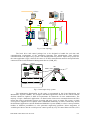
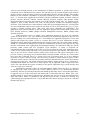
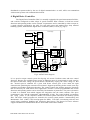
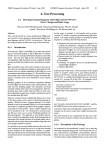
CONTROL NETWORK AS BACK BONE OF THE CRANE MOTION
CONTROL SYSTEM
Alojz Slutej
ABB Automation Systems
72167 Västerås, Sweden
[email protected]
phone: +46 21 340 528
fax: +46 21 340 290
Fetah Kolonić
Faculty of Electrical Eng. and Comp.
Unska 3, HR-10000 Zagreb, Croatia
fetah.kolonić@fer.hr
phone: +385 1 6129 824
fax: +385 1 6129 705
Key words
Control network, integrated crane control, distributed multidrive systems, application controller,
digital drive controller, AC machines, TCP/IP protocol, fast multidrive field bus link.
Abstract
Requirements of modern cranes and another heavy-duty material handling systems result in demand
for sophisticated crane control and automation systems capable of handling loads fast and reliable
connection to the particular information systems. These systems continuously provide up-dated
information about containers moves and crane status. The total function is built up of a number of
distinct building blocks installed from the beginning or added on after. Many of the building blocks
are tightly connected to each other to achieve the right functionality and performance. For steel mill
cranes and another similar industrial systems special attention is paid to the systems robustness,
reliability and availability. Generally, the crane motion control system supports positioning, brake
control, and another application function. In order to achieve a number of different possibilities to
solve engineered problems, the multidrive concept is applied. Mentioned concept includes: powerful
process controller with advanced multitasking, capable of handling several real time critical control
loops simultaneously, high speed communication links between different clients, accurate
measurement and fast transmission of drive positions and speeds and centralized interface for
diagnostics of the complete system. This paper presents the important features of Control Network
used in crane motion concept with Digital Drive Controller (DDC) system. DDC system, based on
operational flexibility through standardized hardware and software modules, offers a solution for
many engineered crane application problems.
1. Introduction
The Integrated Crane Control system is designed for handling of the complete control and
automation of a container crane. The total functions are built up of a number of distinct building
blocks that can be installed from the beginning or added on after the delivery of the crane. Many of
the building blocks are tightly connected to each other and requires as system designed and built with
the total functionality to achieve the right performance (Fig.1).
Panels
•Crane driver
•Checkers cabin
HV Switchgear
Main
Trafo
Aux.
Trafo
CMS
TCP/IP
Main
Controller
Field Bus
PLC
PLC
R-I/O
MCU
MCU
MCU
MCU
MCU
I
SACE F2
MCU
o
MCU
o
MNS®
PK
MCU
MCU
MEGAMA X
MCU
PR112
PR1
Main Drive
Line Up
MNS®
MCU
MNS ®
LV Distr.
MCC
R-I/O
R-I/O
LPS
Sensors
Limit Switches
Main Motion Motors
TPS
Local Control Boxes
Fig 1. Crane topology.
The basic drive and control package has to be designed to handle the real time and
communication requirements of the automation functions. Bus Administrator (BA) achieves
communication to the Supervisory System with standard field bus protocol. Supervisory System for
the crane application (Fig.2) connects all cranes via TCP/IP communication network and optical hubs
connected to the Crane Information Management Server (CIMS_NT).
Crane1
CMMS 6.0
Cabin view
Checkers view
HUB
IEEE802.3, TCP/IP
AC410
Hub
Crane 2
Remote CMMS
Crane IMS_NT
Crane n
Fig 2. Crane supervisory system.
The maintenance functionality on the crane is concentrated in the Crane Monitoring and
Maintenance System (CMMS). The complex distributed applications based on the control network
facilities should be capable to fulfil all requirements for framework of crane modernization. The
majority of open distributed applications are based on the client-server communication model. This
means that client or application process accessing and using server as remote file system. A single
server process supports access requests from a distributed community of clients concurrently. Part of
the distributed application could be Distributed Multidrive System (DMS) as a basic concept with the
number of different possibilities to solve particular engineering problems. Direct integration of
variable speed drives into the overall process control system by way of Control Network Link (CNL)
EPE-PEMC 2002 Dubrovnik & Cavtat
P. 2
and Fast Multidrive Field bus Link (FMFL), brings about a number of advantages, such as simplified
connections, consistent operator supervision or control and improved application program legibility.
In DMS, several Application Controllers (APC) are interconnected by FMFL where each drive is used
as separate node. Common control functions are distributed to separate nodes by the use of digital
communication. The APC takes care of the specific control functions a basically, it could be a single
board controller with all software and hardware facilities needed for a single or multidrive systems.
The functions of the drive controller are independent whether a DC or AC drive applications are used.
For communication to the common overriding control system CNL is used. Mentioned link ensures
high performance, reliability, and availability required for DMS application.
2. Control network link
The Control Network Link (CNL) provides real-time communication link between various
clients or controllers in a complex DMS (Fig.3).
Yard planing system
Administration system
RCMS
Crane 1
Crane 2
Crane 3
Crane n
Fig 3. Crane network topology.
These links are local to the respective clients and can only communicate with clients connected to the
same bus. CNL is designed in accordance with ISO's seven-layer model for Opens System
Interconnection (OSI), [1]. It is used for the time critical, real-time communication within the
distributed control system.
When two or more networks are involved in an application, the mode of working is
normally refereed to as internetworking [1], [2]. The term internetwork or Internet is used to refer to
the composite network. Each constituent network is referred to as a subnet. It is assumed that each
network is of a different type and hence that the router will have a different set of network protocols
associated with each network part. Control network based on Internet is assumed as a subnet. The
CNL’s Medium Access Control (MAC) standard together with associated physical media
specification (contained in the IEEE 802.3 Carrier Sense Multiple Access with Collision Detection
(CSMA/CD) standard's document) are implemented [3], [4]. The MAC sublayer provides the method
by which devices access the shared network transmission medium. The Logical Link Control (LLC)
sublayer provides a network interface to upper-layer protocols and is concerned with transmitting
data between two nodes on the same network segment.
The Internet Protocol is one protocol associated with the complete protocol stack and it is
known as TCP/IP protocol (Transmission Control Protocol/Internet Protocol). Protocol is now
widely used in many commercial and research Internets and includes transport and application layers.
Networking protocols layers are responsible for a different facet of the communication. A protocol
EPE-PEMC 2002 Dubrovnik & Cavtat
P. 3
suite for used TCP/IP protocol is the combination of different protocols at various layers and is
considered to be a minimized 4-layer system. The data link layer or network interface layer includes
the device driver in the operating system and corresponding network interface module. This module
handles all the hardware components of physically interfacing to the network Media. Network
layer or Internet layer supports the movement of packets around the network as well as routing of
packets. Internet Protocol, Internet Control Message Protocol together with Internet Group
Management Protocol provide the network layer in the TCP/IP protocol suite, [5]. Transport layer
supports a flow of data between two hosts. TCP/IP protocol includes two different transport
protocols: TCP (Transmission Control Protocol) and UDP (User Datagram Protocol). TCP and UDP
are two predominant transport layer protocols and both use IP as the network layer [6], [7]. TCP
provides a reliable transport layer; UDP sends and receive datagrams for applications. The
application layer is direct interface to the user application program and could include: Telnet, FTP
(File Transfer Protocol), SNMP (Simple Network Management Protocol), SMTP (Simple Mail
Transfer Protocol).
Telnet provides services to enable a user application program to log on to the operating
system of remote device. User can communicate interactively with another application process as if
the user terminal was connected directly to it. FTP enables user application program to access and
interact with remote file system. Access to a remote file server is a basic requirement in many
distributed control applications. SMTP manages the transfer of mail from one system mail to another.
SNMP is concerned with management of all the communication protocols and supports the total
network environment. API (Application Programming Interface) for application using the TCP/IP
protocols called sockets and TLI (Transport Layer Interface). A socket is end-point for
communications that get bounds to the UDP or TCP port within the node. One application layer
creates a TCP stream socket and binds it to a particular well-known port number. Next application
layer in the host device creates another stream socket which one will request connection to the
previous socket by specifying its host Internet address and port number. Once the two TCP sockets
have been thus connected, there is a virtual circuit set up between them. Up to five different
protocols or sockets could be created. The socket layer contains a certain number of paired "calls"
and these routines protect code that accesses data structures shared between the socket layer and the
protocol-processing layer. The board communication software support package uses a client-server
communication model. The main server reads requests and, if requested, sends a reply back to the
client. The client builds the request according to the specific application layer, sends message and
waits for a reply to be sent back.
Application Controllers (APC) are interconnected by FMFL where each drive is connected
as separate node. High Level Data Link Control (HDLC) protocol is an international standard
(defined by ISO for use on both point-point and multidrop data links) and is used in this application.
It supports Layer 2 of the seven-layer OSI model and is called data link layer. HDLC uses a bitstuffing process to ensure that bit pattern of the delimiter flag does not occur in the fields between
flags. The HDLC frame is synchronous and physical layer provides a method of clocking and
synchronizing the transmitter/receiver. It uses both data and control messages carried in a standard
format frame (Fig.4).
EPE-PEMC 2002 Dubrovnik & Cavtat
P. 4
Start Delim Frame header
8 bits
Flag
8 bits
8 bits
Address Control
I -frame
Check
End Delim
0 to N bits
Information
16bits
C RC
8 bits
Flag
Direction of transmission
D0
D7
Information 0
Ns
P/F
Nr
Ns - Send sequence number
Nr - Receive sequence number
P/F - Poll/Final bit
D0
1
Supervisory
D7
0
S
P/F
Nr
S: RR - Receiver Ready
RNR - ReceiverNot Ready
REJ - REJect
SERJ - Selective REJect
D0
Unnumbered 1
D7
1
U
P/F
U
Unnumbered SARM - Set Asyn Resp Mode
Commands: SARME - Set Asyn Resp Mode Ext
SNRM - Set Normal Resp Mode
SNRME - Set Normal Resp Mode Ext
SABM - Set Asyn Balanced Mode
SABME - Set Asyn Balan Mode Ext
RSET - Reset
FRMR - Frame Reject
DISC
- Disconnect
Unnumbered UA
- Unnumered Acknowledge
Responses: CMDR - Command Reject
FRMR - Frame Reject
DM
- Disconnect Mode
Fig.4. Frame format.
3. Multidrive system
Multidrive system for engineered drive applications includes: built-in distributed application
control, open communication and advanced PC based tools for application programming,
commissioning, trouble shooting and drive monitoring ( Fig 5.)
AC
Common DC Bus
Control
Control
AMC
AMC
AMC
AMC
Inverter
Inverter
Inverter
Inverter
Supply
Unit
AMC
AMC
AMC
AMC
Inverter
Inverter
Inverter
Inverter
(rectifier)
AC
Single drives:
MultiDrive:
• Independent frequency
converters
• Common AC input
• Less components
• Regenerative or resistor braking for
several inverters
• Motor to motor braking with common DC
bus
Fig 5. Multidrive system.
The Application Controller (APC), common for both DC and AC drives, is basically a single
board controller with all the software and hardware facilities needed to handle the application specific
functions, [8]. In distributed controller systems, several application controllers are interconnected by
fast communication link where each drive can be used as a node. Common control functions are
EPE-PEMC 2002 Dubrovnik & Cavtat
P. 5
distributed to separate nodes by the use of digital communication. As well, APC's can communicate
with external systems with communication boards.
4. Digital Drive Controller
The Digital Drive Dontroller (DDC) is normally equipped with speed measurement facilities,
and could be configured as either torque or speed controller. DDC software is fixed but various
functions and operating modes can be selected via parameters and is controlled by either a torque or
a speed reference provided by the APC. For steel mill cranes and another heavy duty material
handling systems, ABB ASTAT Digital Drive Controller (DDC) is used, [9], (Fig 6).
Power supply
Signalization
Fault tracing
Cabin unit
Cabin
No.1. unit
No.1.
Signalization
Fault tracing
Cabin unit
Cabin
No.2. unit
No.2.
Control module
Main control board
Main control board
PC
Servis terminal,
Service Tool,
Developing
system
Thyristor
module
Firing unit
Firing
unit
with
current
with current
feedback
feedback
External
rotor
resistors
Process
Process
unit
unit
Rotor
Rotor
frequency
frequency
estimation
estimation
unit
unit
Brake
Rotor
Rotor
adoption
adoption
unit
unit
Slip-ring
motor
Fig.6. ASTAT block diagram.
It is a speed or torque control system for slip-ring AC motors. Performs stator and rotor control
functions. Because the available motor torque of induction motor is proportional for each speed to
the square of the stator voltage, the speed control is obtained by varying the stator voltage so that
the desired speed is obtained for a given load. Rotor control gives to the motor the right
characteristics optimizing the external rotor resistance. Supports positioning, brake control, rotor step
switching and another application functions. The control system also includes protective functions
that are necessary for crane motor drives application. ASTAT is on line programmable and various
functions and operating modes can be selected by fixed number of parameters. The power electronics
is made in a modular form which supports the integration into the cranes structure. The space
requirement is low, and the temperature withstandability is high. The control module is generating
the firing pulses to the thyristors module. All control system connections are made by optical
fiber. The motor control programs are located in the control system module. Commissioning and
Maintenance Tool (CMT) is PC based program for DDCs. The CMT is monitoring reference and
actual values, parameters handling and displaying data loggers. The Process I/O basic software
support and different communication drivers are located in the control module.
EPE-PEMC 2002 Dubrovnik & Cavtat
P. 6
4. 1. Main Control Module
The control system module is built up around the Motorola MC68332 microcontroller unit, (Fig.7).
M easurem e
Line
S tator
M otor
T em peratu
Local
2 x 7th
D ispla
TP U
C ontro
Firing pulse
B ridge change
QSP
Pow er
24 V in, 5V
Supervisio
QSM
M C 6833
RW
fPR O
D ata
Address
C ontrol
H ost
O pen
O pto 4
SeriaC om m
DCB
RS
P I/O
Field Bus
O pto Link 1
CMT
R S 485/R S
Fig.7. Control system module block diagram.
The control board comprises a number of connectors interfacing other boards or devices. The
MC68332 is a 32-bit integrated microcontroller with powerful peripheral subsystems [2], and
includes an external interface and various functions that reduce the need for external glue logic. The
CPU module configuration registers allows the user to configure and monitor the system according to
the system requirements. The local operating system software sets up the system after a power on
reset. The process I/O and Master/follower communication interface is a high-speed data link based
on the SDLC standard protocol [1]. The PC based Service Tool can communicate with any DDC
connected to the bus. The PC is connected to the RS232/RS485 interface (115.2 kBit/s) of one DDC
and communication to the other DDC's on the same bus is easily accomplished. The messages are
relayed back and forth through that one DDC, [3].
4. 2. Process I/O Control Module
The control module for different type of process I/O units is built up around the Motorola
MC68302 microcontroller unit [10], [11]. The control module (Fig.8.) comprises a number of
connectors interfacing other boards or devices: Control board, another process I/O modules and
service terminal. The MC68302 is a 32-bit Integrated microcontroller with powerful peripheral
subsystems. The device is especially suitable to applications in the communications industry for a
wide variety of DDC’s. The main Communication Processor (CP) is a RISC processor that services
the three Serial Communication Channels (SCC). Serial Direct Memory Access channels are
associated with three full-duplex SCCs. Each channel is permanently assigned to service the receive
or transmit operation of one of the SCCs and is always available, regardless of the SCC protocol
chosen.
EPE-PEMC 2002 Dubrovnik & Cavtat
P. 7
P I/O Comm.
Opto Link
EX P I/O Comm.
Opto Link
SCC1 SCC2 SCC3
MC66302
RWM
DAPU 100
Service Comm.
DCB Prot.
RS 232
fPROM
Power supply
24 Vin, 5V ±15V
Supervision
Data Bus
Address Bus
Control Bus
Digital
Inputs
Digital
Outputs
Analogue
Inputs
Analogue
Outputs
Pulse Enc
Reference
Digital
Outputs
Analogue
Inputs
Analogue
Outputs
Pulse Enc
Reference
RFM Torque
DATX 110
Digital
Inputs
DATX 130
DSP
Rotor
DSP
Stator
Fig.8. Process I/O control module block diagram.
5. Conclusion
The CNL provides real-time communication link between various clients or controllers in a
DMS application. These networks are local to the respective clients and they are used in the complex
DMS to integrate a variable speed drives into overall process control system application. The CNL is
based on the Ethernet/IEEE 802.3 (TCP/IP) protocol and provides a connection-oriented data stream
service between the two end points of user application process. The term stream is used since it
treats all the user data associated with a sequence of request and response messages. Communication
module supports access to the CNL and creates a direct logical interface to the CNL protocol suite
via different sockets. The stream socket layer maps protocol-independent requests from application
layer to the protocol-specific implementation. Up to five different protocols or sockets could be
selected and serviced within less then 20 ms. The FMFL is based on the HDLC protocol and is used
in multidrop configuration. It supports Layer 2 of the seven-layer OSI model and is called data link
layer. Guaranteed data exchange between different clients should be less then 2 ms. Presented Digital
Drive Controller for slip-ring AC motors is suitable for cranes applications where system robustness,
reliability and availability are basic requirements. It supports positioning, brake control, rotor step
switching and another application functions. DDC performs stator and rotor control functions. Stator
control is related to the torque control. Rotor control, by optimising the external rotor resistance,
gives the motor the right characteristics. As a particular sub-system, DDC can be linked in a superior
overriding level for industrial automation and information interchange.
6. References
[1]
[2]
[3]
[4]
[5]
[6]
[7]
[8]
Halsall, F.: Data Communications, Computer Networks and Open systems, Addison-Wesley, 1992.
Rago, S.A.: UNIX System V Network Programming, Addison-Wesley, 1993.
IEEE Pub.: 802.3 CSMA/CD Access Method and Physical Layer Specification, IEEE, 1985.
IEEE Pub.: Logical Link Control ANSI/IEEE Std., IEEE, 1985.
Postel, J.B.: Internet Control Message Protocol, RFC 792, 1994.
Stevens,W.R.: TCP/IP Illustrated, Addison-Wesley, Vol.1, 1994.
Stevens, W.R.: TCP/IP Illustrated, Addison-Wesley, Vol.2, 1994.
Slutej, A.: The new Multidrive concept for engineered drive application, invited paper, in Proceedings of
Conference on Microcomputers in control systems, Mipro’94, Rijeka, Croatia, vol.2, 1994. pp.1-5.
[9] ABB Automation System.: ASTAT Manual, CD ROM, 2001.
[10] Motorola.: Quad Integrated Communication Controller, 1995.
[11] Motorola.: Integrated Multiprotocol Processor, User’s manual, 1991.
EPE-PEMC 2002 Dubrovnik & Cavtat
P. 8
Analphabetic list of important shortcuts:
APC APlication Controller
API
Application Programming Interface
BA
Bus Administrator
CIMS Crane Information Management Server
CMMS Crane Monitor Management Systems
CNL Control Network Link
CSMA Carrier Sense Multiple Access
DDC Distributed Drive Controller
DMS Distributed Multidrive System
FMFL Fast Multidrive Fieldbus Link
FTP
File Transfer Protocol
HDLC High speed Data Link Communication
LLC Logical Link Control
MAC Medium Access Control
OSI
Open System Interconnection
SMTP Simple Mail Transfer Protocol
SNMP Simple Network Management Protocol
TCP/IP Transmission Control Protocol/Internet Protocol
TLI
Transport Layer Interface
UDP User Data Protocol
EPE-PEMC 2002 Dubrovnik & Cavtat
P. 9