Download A Software Lifecycle for Building Groupware Applications: Building

Transcript
A Software Lifecycle for Building
Groupware Applications: Building
Groupware On THYME
A Dissertation
Presented to
The Faculty of the Graduate School of Arts and Sciences
Brandeis University
Computer Science
Richard Alterman, Advisor
In Partial Fulfillment
of the Requirements for the Degree
Doctor of Philosophy
by
Seth M. Landsman
February, 2006
This dissertation, directed and approved by Seth M. Landsman’s committee, has
been accepted and approved by the Graduate Faculty of Brandeis University in
partial fulfillment of the requirements for the degree of:
DOCTOR OF PHILOSOPHY
Adam B. Jaffe, Dean of Arts and Sciences
Dissertation Committee:
Richard Alterman, Chair
Timothy Hickey
Mitch Cherniack
John Patterson
c
Copyright
by
Seth M. Landsman
2006
This work is dedicated to Gale Wilcow, Rita Treiber, Jennie Landsman, Abraham
Landsman, and others who could not be here today.
Acknowledgments
The author wishes to thank the students and teaching assistants who participated in
the Human-Computer Interaction class (COSI 125a), which contributed to the results
discussed in 6.
The author also wishes to thank Alexander Feinman, Heather Quinn, David Wittenberg, Richard Alterman, and the members of my committee for their comments
on previous versions of this work.
My advisor, Richard Alterman, provided invaluable guidance and help throughout
this process. Additionally, the members of my committee provided advice and input
that was greatly appreciated.
This work would not have been completed if not for the members of the research
group, as well as those who I am privileged to call friends, family, and colleagues.
They listened to my endless stream of ideas, frustrations, and accomplishments. The
quality of this work is a direct testament to their help.
My wife, who was by my side from the beginning of this journey, deserves as much
credit as I do. I would not have gotten through this process without her.
This work was supported under ONR grants N000-14-96-1-0440 and N000-14-021-0131.
v
Abstract
A Software Lifecycle for Building Groupware Applications:
Building Groupware On THYME
A dissertation presented to the Faculty of
the Graduate School of Arts and Sciences of
Brandeis University, Waltham, Massachusetts
by Seth M. Landsman
As corporations and organizations become more distributed, the use of groupware
applications as part of day-to-day activities becomes more prevalent. A successful
groupware application must work as expected by the developer and the community of
users. In practice, however, assumptions made by the developer may not match the
expectations of the users. For groupware applications to be built that fully support
the community of users, an engineering methodology is required.
This work describes a methodology for engineering groupware applications. This
methodology incorporates a modified version of Boehm’s spiral evolutionary software
model. The modified software model incorporates explicit analysis of the application
during each prototype spiral, giving insight as to how the application performs during
actual use and allowing the application to be adapted over time. The types of software
tools and methods required to support this methodology are also discussed. This
thesis further focuses on how to rapidly build, modify, and analyze the groupware
application within limited budgetary constraints.
Four major case studies are detailed that support the claims made in this work.
The first shows early attempts to build a groupware application and understand the
limitations of the traditional engineering process. The second illustrates how the
lifecycle can support the end-to-end engineering of a groupware application, from
initial building to analysis. The third and fourth case studies showcase additional
vi
vii
uses of the these techniques, including how the reference toolkits and development
model were used in a classroom term project and how an example system built in the
classroom was used as the basis of an experimental platform.
Contents
Abstract
vi
1 Introduction
1.1 Online Ethnographic Analysis of
1.2 A Case Study . . . . . . . . . .
1.3 The Thesis Problem . . . . . .
1.4 Contribution of this Thesis . . .
1.5 Organization of the Thesis . . .
.
.
.
.
.
.
.
.
.
.
.
.
.
.
.
.
.
.
.
.
.
.
.
.
.
.
.
.
.
.
.
.
.
.
.
.
.
.
.
.
.
.
.
.
.
.
.
.
.
.
.
.
.
.
.
1
4
8
21
25
26
.
.
.
.
.
.
.
.
.
.
.
.
.
.
.
.
.
.
.
.
.
.
.
.
.
.
.
.
.
.
.
.
.
.
.
.
.
.
.
.
.
.
.
.
28
29
34
40
48
. . . . . . . . .
. . . . . . . . .
Using THYME
. . . . . . . . .
.
.
.
.
.
.
.
.
.
.
.
.
.
.
.
.
.
.
.
.
.
.
.
.
50
53
68
85
88
. . . . . . .
. . . . . . .
. . . . . . .
and SAGE
. . . . . . .
. . . . . . .
. . . . . . .
89
91
91
95
97
105
111
112
Online Behavior
. . . . . . . . . .
. . . . . . . . . .
. . . . . . . . . .
. . . . . . . . . .
2 Related Literature
2.1 Groupware Applications . . . . . . . . .
2.2 Analysis of Groupware Use . . . . . . . .
2.3 Engineering the Groupware Application .
2.4 The Remainder of the Thesis . . . . . .
.
.
.
.
3 Building Groupware Applications
3.1 Distributed Component Model . . . . . . .
3.2 Groupware Components . . . . . . . . . .
3.3 Case Study: Building a Groupware System
3.4 Conclusions . . . . . . . . . . . . . . . . .
.
.
.
.
.
.
.
.
.
.
.
.
.
.
.
.
4 Observational Analysis of Groupware Applications
4.1 Online Research Application . . . . . . . . . . . . . . . .
4.2 Example Analysis with ORA . . . . . . . . . . . . . . . .
4.3 Transcription and Replay, Revisited . . . . . . . . . . . .
4.4 Supporting Online Ethnographic Analysis Using THYME
4.5 Generating the Replay Application . . . . . . . . . . . .
4.6 Other Visualization Techniques . . . . . . . . . . . . . .
4.7 Conclusions . . . . . . . . . . . . . . . . . . . . . . . . .
5 Distributing Computing Applications
114
5.1 Multi-Component Routing . . . . . . . . . . . . . . . . . . . . . . . . 115
5.2 Discovery . . . . . . . . . . . . . . . . . . . . . . . . . . . . . . . . . 117
viii
ix
CONTENTS
5.3
5.4
5.5
Transcription Support . . . . . . . . . . . . . . . . . . . . . . . . . . 121
Conclusion . . . . . . . . . . . . . . . . . . . . . . . . . . . . . . . . . 121
Version . . . . . . . . . . . . . . . . . . . . . . . . . . . . . . . . . . . 122
6 Use
6.1
6.2
6.3
6.4
of THYME in the Classroom
The Term Project . . . . . . . . .
Resulting Projects . . . . . . . .
Analysis . . . . . . . . . . . . . .
Conclusions . . . . . . . . . . . .
.
.
.
.
123
124
125
131
135
7 The
7.1
7.2
7.3
Lifecycle Revisited
Software Lifecycles . . . . . . . . . . . . . . . . . . . . . . . . . . . .
The Integrated Lifecycle . . . . . . . . . . . . . . . . . . . . . . . . .
The Workforce Application . . . . . . . . . . . . . . . . . . . . . . . .
138
139
144
147
.
.
.
.
.
.
.
.
.
.
.
.
.
.
.
.
.
.
.
.
.
.
.
.
.
.
.
.
.
.
.
.
.
.
.
.
.
.
.
.
.
.
.
.
.
.
.
.
.
.
.
.
.
.
.
.
.
.
.
.
.
.
.
.
.
.
.
.
.
.
.
.
.
.
.
.
8 Summary and Future Work
156
8.1 Future Work . . . . . . . . . . . . . . . . . . . . . . . . . . . . . . . . 158
8.2 Final Statement . . . . . . . . . . . . . . . . . . . . . . . . . . . . . . 162
A The
A.1
A.2
A.3
Tiny THYMEr
170
Introduction . . . . . . . . . . . . . . . . . . . . . . . . . . . . . . . . 170
Concepts . . . . . . . . . . . . . . . . . . . . . . . . . . . . . . . . . . 170
Your Application . . . . . . . . . . . . . . . . . . . . . . . . . . . . . 179
B Source Code to the ORA Application
B.1 package orav2 . . . . . . . . . . . . .
B.2 package orav2.bloc . . . . . . . . . .
B.3 package orav2.iface . . . . . . . . . .
B.4 ORAv2 specification files . . . . . . .
C The
C.1
C.2
C.3
C.4
C.5
C.6
C.7
THYME Widget Tutorial
Introduction . . . . . . . . . .
About The Tutorial . . . . . .
Introduction To The Tutorial
Overview of a Widget . . . . .
Implementing a Widget . . . .
Specification Files . . . . . . .
Conclusions . . . . . . . . . .
.
.
.
.
.
.
.
.
.
.
.
.
.
.
.
.
.
.
.
.
.
.
.
.
.
.
.
.
.
.
.
.
.
.
.
.
.
.
.
.
.
.
.
.
.
.
.
.
.
.
.
.
.
.
.
.
.
.
.
.
.
.
.
.
.
.
.
.
.
.
.
.
.
.
.
.
.
.
.
.
.
.
.
D VesselWorld User Manual
D.1 Starting Up . . . . . . . . . . . . . . . . . . .
D.2 Information and Manipulation of VesselWorld
D.3 Planning and the Planning Window . . . . . .
D.4 Coordinating with other Captains . . . . . . .
.
.
.
.
.
.
.
.
.
.
.
.
.
.
.
.
.
.
.
.
.
.
.
.
.
.
.
.
.
.
.
.
.
.
.
.
.
.
.
.
.
.
.
.
.
.
.
.
.
.
.
.
.
.
.
.
.
.
.
.
.
.
.
.
.
.
.
.
.
.
.
.
.
.
.
.
.
.
.
.
.
.
.
.
.
.
.
.
.
.
.
.
.
.
.
.
.
.
.
.
.
.
.
.
.
.
.
.
.
.
.
.
.
.
.
.
.
.
.
.
.
.
.
.
.
.
.
.
.
.
.
.
.
.
.
.
.
.
.
.
.
.
.
.
.
.
.
.
.
.
.
.
.
.
.
.
.
.
.
.
.
.
.
.
.
.
.
.
.
.
.
.
.
.
.
.
.
.
.
.
.
.
.
.
193
193
193
202
204
.
.
.
.
.
.
.
206
206
206
207
208
209
215
217
.
.
.
.
219
219
224
231
234
List of Figures
1.1
1.2
1.3
1.4
1.5
1.6
1.7
1.8
A congressional GAO study . . . . . . . . . . . .
The VW-SAGE system . . . . . . . . . . . . . . .
An example of VesselWorld dialogue . . . . . . .
The subsystem interaction . . . . . . . . . . . . .
The subsystem model . . . . . . . . . . . . . . . .
GComponent and GModel interaction . . . . . . .
The shared web browser component layout . . . .
The shared web browser transcription mechanism
.
.
.
.
.
.
.
.
.
.
.
.
.
.
.
.
.
.
.
.
.
.
.
.
.
.
.
.
.
.
.
.
.
.
.
.
.
.
.
.
.
.
.
.
.
.
.
.
.
.
.
.
.
.
.
.
.
.
.
.
.
.
.
.
.
.
.
.
.
.
.
.
.
.
.
.
.
.
.
.
.
.
.
.
.
.
.
.
3
13
16
17
18
20
23
24
2.1
2.2
2.3
2.4
2.5
Temporality and locality matrix
The WYSIWIS spectrum . . . .
The DISCIPLE framework . . .
The GroupKit framework . . .
The GROOVE framework . . .
.
.
.
.
.
.
.
.
.
.
.
.
.
.
.
.
.
.
.
.
.
.
.
.
.
.
.
.
.
.
.
.
.
.
.
.
.
.
.
.
.
.
.
.
.
.
.
.
.
.
.
.
.
.
.
.
.
.
.
.
.
.
.
.
.
.
.
.
.
.
30
31
44
46
48
3.1
3.2
3.3
3.4
3.5
3.6
3.7
3.8
3.9
3.10
3.11
3.12
3.13
3.14
The chat room . . . . . . . . . . . . . . . . .
Chat room components . . . . . . . . . . . . .
Layers of THYME libraries . . . . . . . . . . .
Components and services . . . . . . . . . . . .
Messages, data, and identifiers . . . . . . . . .
Basic THYME component interaction . . . . .
A routing example in the chat room . . . . . .
A non-local routing example in the chat room
Message flow in a room application . . . . . .
The shared whiteboard . . . . . . . . . . . . .
The shared browser . . . . . . . . . . . . . . .
The shared editor . . . . . . . . . . . . . . . .
The ORA application . . . . . . . . . . . . . .
The assembled composite application . . . . .
.
.
.
.
.
.
.
.
.
.
.
.
.
.
.
.
.
.
.
.
.
.
.
.
.
.
.
.
.
.
.
.
.
.
.
.
.
.
.
.
.
.
.
.
.
.
.
.
.
.
.
.
.
.
.
.
.
.
.
.
.
.
.
.
.
.
.
.
.
.
.
.
.
.
.
.
.
.
.
.
.
.
.
.
.
.
.
.
.
.
.
.
.
.
.
.
.
.
.
.
.
.
.
.
.
.
.
.
.
.
.
.
.
.
.
.
.
.
.
.
.
.
.
.
.
.
.
.
.
.
.
.
.
.
.
.
.
.
.
.
.
.
.
.
.
.
.
.
.
.
.
.
.
.
.
.
.
.
.
.
.
.
.
.
.
.
.
.
.
.
.
.
.
.
.
.
.
.
.
.
.
.
51
52
53
54
54
65
66
69
78
82
83
85
86
87
4.1
4.2
4.3
The SAGE replay application for the online research application . . . 92
Logging messages in a THYME application . . . . . . . . . . . . . . . 99
SAGE playback controller . . . . . . . . . . . . . . . . . . . . . . . . 105
.
.
.
.
.
x
.
.
.
.
.
.
.
.
.
.
.
.
.
.
.
.
.
.
.
.
.
.
.
.
.
.
.
.
.
.
xi
LIST OF FIGURES
4.4
4.5
4.6
4.7
The SAGE application generator . . . . . . . . .
Leveraging a basis component in generation of the
A sample discourse tagging . . . . . . . . . . . . .
Life span tool . . . . . . . . . . . . . . . . . . . .
5.1
The node neighborhood for A . . . . . . . . . . . . . . . . . . . . . . 120
6.1
6.2
6.3
6.4
6.5
6.6
Term project schedule . . . . . . . . . . . .
Screenshot of the online research assistant .
Screenshot of the RA scheduler . . . . . . .
Screenshot of the group crossword puzzle . .
Chart of project data . . . . . . . . . . . . .
Component and subsystem layout in ORAv2
.
.
.
.
.
.
.
.
.
.
.
.
.
.
.
.
.
.
.
.
.
.
.
.
125
127
128
131
132
137
7.1
7.2
7.3
7.4
7.5
7.6
7.7
7.8
7.9
The waterfall software model . . . . . . . . . . . . . . . . . . . .
The incremental software model . . . . . . . . . . . . . . . . . .
The spiral software model . . . . . . . . . . . . . . . . . . . . .
The integrated software lifecycle . . . . . . . . . . . . . . . . . .
The workforce application . . . . . . . . . . . . . . . . . . . . .
The SAGE replay application for the workforce application . . .
The counterstrike application . . . . . . . . . . . . . . . . . . .
Layout of the component views in the counterstrike application
Layout of the component views in the workforce application . .
.
.
.
.
.
.
.
.
.
.
.
.
.
.
.
.
.
.
.
.
.
.
.
.
.
.
.
141
142
143
145
148
149
150
151
152
.
.
.
.
.
.
.
.
.
.
.
.
.
.
.
.
.
.
. . . . . . . . . . .
replay application
. . . . . . . . . . .
. . . . . . . . . . .
.
.
.
.
.
.
.
.
.
.
.
.
.
.
.
.
.
.
.
.
.
.
.
.
.
.
.
.
.
.
.
.
.
.
.
.
.
.
.
.
.
.
106
107
111
112
A.1 THYME objects . . . . . . . . . . . . . . . . . . . . . .
A.2 Specification of the chat room . . . . . . . . . . . . . . .
A.3 The component layout of the chat room . . . . . . . . .
A.4 Class declaration for the chat room . . . . . . . . . . . .
A.5 Basic chat room receive method . . . . . . . . . . . . . .
A.6 Dispatching chat room receive method . . . . . . . . . .
A.7 Handler for chat room communication . . . . . . . . . .
A.8 Designated chat room constructor . . . . . . . . . . . . .
A.9 UI for the chat client . . . . . . . . . . . . . . . . . . . .
A.10 actionPerformed() method for the ChatClientView . . . .
A.11 Receive() method for ChatClientView . . . . . . . . . . .
A.12 handleChatCommuncation() method for ChatClientView
A.13 handleRoomRegistration() method for ChatClientView .
A.14 onInit() method for the ChatClientView . . . . . . . . .
.
.
.
.
.
.
.
.
.
.
.
.
.
.
.
.
.
.
.
.
.
.
.
.
.
.
.
.
.
.
.
.
.
.
.
.
.
.
.
.
.
.
.
.
.
.
.
.
.
.
.
.
.
.
.
.
.
.
.
.
.
.
.
.
.
.
.
.
.
.
.
.
.
.
.
.
.
.
.
.
.
.
.
.
.
.
.
.
.
.
.
.
.
.
.
.
.
.
172
176
185
186
186
187
187
188
189
190
191
191
192
192
C.1
C.2
C.3
C.4
C.5
.
.
.
.
.
.
.
.
.
.
.
.
.
.
.
.
.
.
.
.
.
.
.
.
.
.
.
.
.
.
.
.
.
.
.
208
209
210
211
212
Room-based communication . . . . . . . . . . . . . .
Widget class inheritance . . . . . . . . . . . . . . . .
Partial implementation of SharedTreeActionType . .
Partial implementation of SharedTreeActionMessage
Partial implementation of SharedTreeModel . . . . .
.
.
.
.
.
.
.
.
.
.
xii
LIST OF FIGURES
C.6
C.7
C.8
C.9
C.10
C.11
Partial implementation of SharedTreeModel
Example tree operation . . . . . . . . . . . .
Initializer source . . . . . . . . . . . . . . .
The room specification . . . . . . . . . . . .
The client specification . . . . . . . . . . . .
D.1 The login window . . . . . . . . . . . . .
D.2 An inhabitant and its zone . . . . . . . .
D.3 Cranes, equipment, and joined operation
D.4 The tug . . . . . . . . . . . . . . . . . .
D.5 A barrel of toxic waste . . . . . . . . . .
D.6 A leaking barrel of toxic waste . . . . . .
D.7 The large barge . . . . . . . . . . . . . .
D.8 A small barge . . . . . . . . . . . . . . .
D.9 The control center . . . . . . . . . . . .
D.10 The marker list . . . . . . . . . . . . . .
D.11 Adding a marker . . . . . . . . . . . . .
D.12 The weather window . . . . . . . . . . .
D.13 The information window . . . . . . . . .
D.14 The legend window . . . . . . . . . . . .
D.15 The score window . . . . . . . . . . . . .
D.16 The planning window . . . . . . . . . . .
D.17 The chat window . . . . . . . . . . . . .
D.18 The object list window . . . . . . . . . .
D.19 The strategic planning window . . . . . .
.
.
.
.
.
.
.
.
.
.
.
.
.
.
.
.
.
.
.
.
.
.
.
.
.
.
.
.
.
.
.
.
.
.
.
.
.
.
.
.
.
.
.
.
.
.
.
.
.
.
.
.
.
.
.
.
.
.
.
.
.
.
.
.
.
.
.
.
.
.
.
.
.
.
.
.
.
.
.
.
.
.
.
.
.
.
.
.
.
.
.
.
.
.
.
.
.
.
.
.
.
.
.
.
.
.
.
.
.
.
.
.
.
.
.
.
.
.
.
.
.
.
213
214
214
216
217
218
.
.
.
.
.
.
.
.
.
.
.
.
.
.
.
.
.
.
.
.
.
.
.
.
.
.
.
.
.
.
.
.
.
.
.
.
.
.
.
.
.
.
.
.
.
.
.
.
.
.
.
.
.
.
.
.
.
.
.
.
.
.
.
.
.
.
.
.
.
.
.
.
.
.
.
.
.
.
.
.
.
.
.
.
.
.
.
.
.
.
.
.
.
.
.
.
.
.
.
.
.
.
.
.
.
.
.
.
.
.
.
.
.
.
.
.
.
.
.
.
.
.
.
.
.
.
.
.
.
.
.
.
.
.
.
.
.
.
.
.
.
.
.
.
.
.
.
.
.
.
.
.
.
.
.
.
.
.
.
.
.
.
.
.
.
.
.
.
.
.
.
.
.
.
.
.
.
.
.
.
.
.
.
.
.
.
.
.
.
.
.
.
.
.
.
.
.
.
.
.
.
.
.
.
.
.
.
.
.
.
.
.
.
.
.
.
.
.
.
.
.
.
.
.
.
.
.
.
.
.
.
.
.
.
.
.
.
.
.
.
.
.
.
.
.
.
.
.
.
.
.
.
.
.
.
.
.
.
.
.
.
.
.
.
.
.
220
220
221
222
222
223
223
224
225
227
227
228
229
230
231
233
235
236
237
Chapter 1
Introduction
Businesses are becoming increasingly globalized, and major organizations and corporations act as distributed enterprises, with offices, employees, clients, and consultants
spread throughout the world. People in different locations need to collaborate to
achieve company and organizational goals. In-person meetings are desirable and effective, but the cost of travel can be an unaffordable luxury, expensive in terms of
material costs, but also in the time spent away from the office and the associated lost
productivity.
In his book, Designing the User Interface [Shn98], Shneiderman says:
Goal-directed people quickly recognized the benefits of electronic cooperation and potential to live in the immediacy of the networked global
village. The distance to colleagues is measured not in miles, but rather
in intellectual compatibility and responsiveness; a close friend is someone
who responds from 3000 miles away within three minutes at three A.M.
with the reference you need to finish a paper.
Corporate employees do not work in an eight-hour-a-day configuration. Players
in the global economy exist in all time zones, and they must make business decisions
1
CHAPTER 1. INTRODUCTION
2
correctly and quickly, no matter the hour. Collaborative applications can enable
organization-wide work to continue after traditional working hours.
Beyond the need to be competitive, collaboration also improves overall productivity. An agile corporation succeeds through the intelligent use of its personnel by
leveraging each worker’s abilities and knowledge. Coordination between employees is
necessary in order to share and support the tasks required by the organization. These
software applications that mediate the distributed work of a community of users as
they work towards a common goal are collectively called groupware [EGR91].
All software, especially groupware applications, are not fixed entities. They evolve
and change constantly, both during development and after fielding. Software needs to
change in order to accommodate different work flows, different groups of users, and
changing business environments, all of which invalidates the view of software as fixed,
static objects. Figure 1.1 shows a Congressional General Accounting Office study,
which illustrates that only 2% of acquired software products are deployed in the state
in which they are delivered, and that this percentage is not improving, despite sixteen
years of progress in the field [Off].
Consequently, once a groupware application is built and deployed, the application
needs to be open to study and analysis. Our understanding of how to build better
collaborative tools is improved through understanding how collaboration occurs in
the field.
Presented in this work is an approach to developing groupware that is tailored to
its community of users. The model of software development depends on an integrated
software lifecycle, where the observation of the application’s use a first-class member
of the lifecycle. The observation of use is accomplished primarily through ethnographic
analysis [ST91] of transcripts of online activity. Quantitative and other qualitative
measures further support the analysis.
3
CHAPTER 1. INTRODUCTION
!
2
"
#
$
%
&
#
'
#
(
)
*
+
3
4
%
(
5
6
'
)
*
/
#
&
#
'
,
#
&
#
*
.
.
#
/
/
0
*
$
$
1
2
/
#
(
"
#
$
%
&
#
(
)
*
+
#
9
/
%
&
'
#
$
#
;
6
'
<
/
#
#
(
>
0
+
#
'
2
/
#
(
>
/
1
@
#
+
2
8
'
:
-
#
+
7
,
A
4
9
B
#
/
"
#
$
%
&
#
'
#
(
(
=
'
>
?
4
9
(
6
9
#
(
Figure 1.1: A congressional GAO study
(
CHAPTER 1. INTRODUCTION
1.1
4
Online Ethnographic Analysis of Online Behavior
A user-centric application is typically adjusted to its community of users through the
following procedure [Ehr99]:
1. A groupware application is developed that reflects the initial customer requirements.
2. User feedback is collected from focus groups during the testing of the application.
3. Potential customers work with early, or “beta” versions of the software, and
their feedback helps the developers tune their software before deployment.
4. Opinions are collected from focus groups. Other “low-tech” forms of observations provide additional feedback; these include looking over the shoulder,
interviewing users, and collecting defect report.
5. Given feedback from initial deployment of the application, it is further modifed
before its release.
Once the deployment of an application has succeeded, its use in the field may or
may not be as envisioned by the designers of the system. Different groups of users may
have needs that are mismatched with the way the application was designed. Thus,
usage patterns frequently vary from what the developers expected. A small change
in expected user behavior might, for example, result in a significant deviation from
the expected usage. An application’s incompatibility with consumer expectations is
often reported to the developer in the form of defect reports, constructive feedback,
or general reports of dissatisfaction with the application.
CHAPTER 1. INTRODUCTION
5
In all of these cases, the data is second-hand and subjective. The user may want to
be helpful. He may try to provide a complete and precise report, including his intent
in the action he was performing, the context of the application when he performed
his action, and the way in which he thought the application failed. However, this
information is potentially flawed, colored by how he expects the application to act
and react. If a breakdown or system failure is technical in nature, a precise, automated
report may be generated, which may give the developer enough information to trace
the user activity in sufficient detail to determine the cause. However, if the failure
was conceptual, in that the application did not behave as the user thought it should,
the developer only has the user-supplied report to use as a basis for investigation.
An approach to analyzing collaboration in a more precise and objective way is
to have the system produce transcripts of online activity. Subsequently, if necessary, these transcripts can be analyzed, providing the developer with more objective
and complete data. The transcript provides a basis for analyzing individual and collective user behavior in the larger context of the online collaborative activity. By
using ethnographic analysis, the developer can learn how people use the application
to perform the prescribed task. By using these kinds of techniques, the researcher
can develop user models of interaction [Hut95] [Hut96] [SSJ74], develop theories of
breakdowns of the collaboration [Gar67] [Eas96], and hypothesize how collaboration
should be changed to better support the activity [AFIL01].
There are existing methods for collecting data of usage and performing an analysis
of activity, including videotaping user activity [ST91] or capturing raw events and
replaying them [SCFP00]. Our approach involves building analysis capabilities into
the collaborative application itself, by allowing replay of the system’s use to occur at
an integrated level within the semantics of the application.
CHAPTER 1. INTRODUCTION
6
Developers need to collect sufficient information to determine how the application was used, where it may have broken down conceptually, or where it may have
failed technically. Because analysis is a fundamental part of the application, this
information can be collected from the field. The replay of the application’s use can
drive the design, redesign, and development tasks in a precise manner, combining
the developer’s technical understanding of the application, the user’s context in using
the application, and the interactive information describing what the user was doing
during the breakdown.
Integrated ethnographic analysis has advantages not found in other techniques.
External forms of ethnographic analysis, such as videotaping activity, will result in
missing information that may be critical to determining how the collaborative task
progressed. Determining, through an external ethnographic record, how one user’s
action influenced another user’s application context requires extensive knowledge of
the internal workings of the collaboration. An external perspective does not allow
such software-based causal links to be tracked. With the replay method described
herein, the context can be built up incrementally, and it is possible to understand
the effect of each action taken by any member of the group. Searching and classification of activity is also possible when analysis is integrated into the application. For
example, a user interface designer interested in learning how a specific grouping of
widgets is used may want the replay to stop at every access to those widgets, which
requires the replay application to be able to detect access to those widgets. An external collection perspective would not have that capability. Overall, the integration of
analysis into the application provides access to the usage patterns and gives a much
deeper understanding of how the system is used and what changes need to be made
to the application. Defect reports and other subjective data about the application
lack context and precise definitions of what was being done. Quantitative measures,
CHAPTER 1. INTRODUCTION
7
such as GOMS [JK96], may aid an analyst in determining which user interface activities carried the largest cognitive cost, but cannot help in determining if that cost
was related to the activity context or conditions of the group collaborative activity. External replay does not help to understand the consequences of user activity;
therefore, even though it is possible to observe individual user actions, this strategy
does not provide enough information. Only ethnographic analysis that is collected
from within the application provides the context, provides the capacity to examine
individual actions and activity, and shows the consequences of the group activity.
Not all internal replay collection techniques provide sufficient information to completely understand the user activity in context. Non-invasive techniques, such as
jRapture [SCFP00], collect raw events within a running Java application. This technique requires changing the underlying Java libraries, but it requires no changes to
the application. Replay is accomplished by re-injecting those raw events into the
application via the changed Java libraries and provides the ability to do ethnographic
analysis, but only at the level of raw activity. Determining the user’s intent behind
the executing activity is not possible, since every button press and every mouse click
look the same. This technique also does not provide any access to group activity,
only to individual activity.
The investigation into online ethnographic analysis points to the need for integrated, meaningful groupware application replay. To record an action, the analysis
application must encode the raw events (i.e., mouse click), as well as determine the
meaning of each raw event within the context of the application (i.e., selecting the
object waste1 ). To get this level of integration and information, though, is expensive.
While building such tools is useful, for all the reasons described here, extensive implementation work is required to do so. The solution to making it possible for these
tools to be used is reducing the amount of work required to create them.
CHAPTER 1. INTRODUCTION
8
This thesis will explore a successful approach employed to decrease the cost of
building these tools by integrating the capabilities into the technology used to construct an application. The toolkits, THYME and SAGE, are presented as a proof of
concept of how these capabilities can be achieved.
1.2
A Case Study
To study same-time computer-mediated collaboration, the VesselWorld [ALFI98]
[LAFI01] experimental groupware platform was constructed. There are three major research activities that were based on the platform. The work that this thesis is
based on extracted methods, technology, and techniques for rapidly building groupware applications and allowing the capture of complete, replayable transcripts of user
activity in an integrated lifecycle. The second activity was to develop analysis techniques that may be applied to the transcripts of user behavior that were constructed
using this platform [FA03]. The last was concerned with adding adaptive components
to groupware applications [IA03].
The remainder of this section will discuss the VesselWorld platform, how it personified an early implementation of online ethnographic analysis and the integrated
lifecycle, and how the approach to building analyzable groupware applications evolved
as the limitations of these early efforts became clear.
The utility of replay in VesselWorld was clearly demonstrated in understanding
how VesselWorld mediated collaboration and in redesigning the VesselWorld application. Constructing the VesselWorld replay application from scratch, though, was
not scalable. The required investment for building this application was much too
great. Instead, the approach that was chosen for building the replay application
hinged around taking the existing VesselWorld system and using its constituent parts
CHAPTER 1. INTRODUCTION
9
to build the replay application. The design of VesselWorld lends itself to this manipulation thanks to its component-oriented design. Individual VesselWorld subsystems
have very distinct points of coupling, allowing them to be transferred to the new
application. This design, however, was not generalizable directly to other groupware
applications. This dissertation builds on the lessons learned, providing a more general solution to building groupware applications that produce complete, replayable
transcripts.
1.2.1
The VesselWorld Platform and Its Integrated Lifecycle
The problem domain encoded in the VesselWorld application has three participants
engage in a computer-mediated problem solving session. To complete a set of tasks in
this simulated environment, the participants must communicate and jointly problemsolve. The only avenue of communication is via the application client. Access to
the environment, and objects in the environment, is also mediated through representations provided by the software application. The problem solving sessions require
cooperation, coordination and collaboration. A more complete description of the
VesselWorld environment can be found in Appendix D.
There were two implementations of the VesselWorld environment. In the original implementation, referred to as the base VesselWorld application, participants can
only exchange information using a text-based chat room. Replay was used to study
the discourse and interaction, providing insight as to what new collaborative tools
would be most effective. The re-design of VesselWorld changed how the users’ collaborated by introducing special-purpose shared representations (called Coordinating
Representations) that were specifically designed to augment user interaction during
recurrent activities. The re-engineered version is the adapted VesselWorld system.
CHAPTER 1. INTRODUCTION
1.2.2
10
Transcript and Replay in VesselWorld
The production of complete, replayable transcripts for VesselWorld problem solving
sessions was accomplished through two features of the VesselWorld software. A transcription subsystem collected complete records of all user activity, including both
user interface-level interaction (such as mouse clicks) and activity information (such
as sending a chat message). The transcript is stored in text files that are easy to
parse and process. The replay system, called VW-SAGE, consumes the VesselWorld
transcript and displays it in a modified version of the VesselWorld application. By
using a modified version of VesselWorld instead of writing a new application the cost
of adding the transcription and replay capabilities was signficantly reduced.
Interviews, questionnaires, and measurements of performance are all important
characterizations of the effectiveness of user behavior. From the designer’s point
of view, however, the availability of a reviewable complete transcript of the online
community at work provided a highly significant class of information that enables
the analyst to closely examine the online work and practice of the community. A
complete transcript of an online session of use captures both domain actions and user
interface events. It also contains information sufficient to recreate the state of the
application at each point in time [LA02].
In a VesselWorld session, a domain action may be to construct a plan. Doing
so involves interface actions like pointing, clicking, and typing within the interface.
Domain actions are constructed from interface actions, although there is not a clear
one-to-one mapping between a set of interface actions and domain actions. For example, the identical plan can result from different sets of interface actions depending
on whether has to correct a typing error or not. An analysis of both domain and
user interface actions is relevant to the re-design of the application and its interface.
CHAPTER 1. INTRODUCTION
11
An ideal improvement in the system makes the collaboration within the system more
effective (an improvement in the domain) while also reducing the amount of work the
user needs to accomplish his task (an improvement in the interface).
The replay application provides access to the transcript of an online session of
system use from an observational perspective. The functions provided by the replay
application dictate how successfully the analyst can work with the transcript. Our
identified set of basic functionality includes:
• Replay the transcript,
• Stop the replay of the transcript and resume from that point,
• Stop the replay at certain types of actions,
• Vary speed at which the transcript is replayed,
• Rewind the transcript and resume play from a previous point,
• Annotate the transcript and store annotations within the transcript,
• Produce aggregate information. i.e., produce a count of the number of domains
and/or user interface actions of a given type.
The VesselWorld platform automatically produces complete, replayable transcripts.
All events that occur during a VesselWorld problem solving session are recorded in
a transcript by the system. Every mouse click, every event, every shared item of
information is recorded within the transcript for a session. Domain events, such as a
“planning event” or a “chat event”, were also included in the transcript.
The VW-SAGE application was built to review the decision making of each group
and examine how the participants in a VesselWorld session coordinate their activities
and the exchange of information. The replay application enabled an analyst to review
CHAPTER 1. INTRODUCTION
12
a session of problem solving from an omniscient perspective by consolidating the
individual views into a useful format for the analyst. Because the data saved had an
inherent structure, the analyst could search through the data using any number of
criteria; e.g., he could move forward to the next communication, round, plan action,
or other such action within the system, allowing for easier review of the extensive
data logs.
Figure 1.2 shows the playback device that was built for the adapted implementation of the VesselWorld platform. Starting in the upper left-hand corner of the
figure and moving clockwise, the following windows of information are provided for
the analyst:
1. The chat window,
2. The current plans of all the users (this view is the omniscient perspective of the
participants’ plans),
3. The layout of the task environment (the “harbor”) and the location of all ’objects’; again this view is from the omniscient user perspective.
4. An annotation window that can be used by the analyst to comment on a particular state of the problem-solving session,
5. The controller for the playback device,
6. A list of shared markers created by the users.
The controller enables the analyst to step through the data using any number of
metrics, e.g., it can move forward to the next communication, round, or bookmark.
The analyst can also fast forward through the data. The controller displays information about the current round being represented, the current time, and the number of
rounds in the session.
CHAPTER 1. INTRODUCTION
Figure 1.2: The VW-SAGE system
13
CHAPTER 1. INTRODUCTION
14
Example Analysis
As part of the VesselWorld experimentation, several analysis sessions were conducted
to determine how the application needed to be changed to better support the problem
solving activity. Further discussion of this analysis can be found elsewhere [AFIL01].
The analysis presented here used the base version of the VesselWorld application.
Primarily, the electronic chatting that took place among the participants was analyzed. As the analyst views the discourse, he observes the most common interactions
and errors in coordination. Conclusions can be drawn as to what other tools and
coordinating representations are needed to support the collaboration.
The users engaged in several types of methods of communication to organize their
activity:
• Planning
– Planning activity
– Identifying tasks
• Delimiting activity
– Entry and exit into phases
– Synchronization
– Turn-taking
• Developing conventions
• Co-referencing
– Reference to status
– Reference to location
CHAPTER 1. INTRODUCTION
15
– Reference to identity of the object
– Reference to features
Figure 1.3 shows the chat that was associated with part of one such analysis where
activity needed to be closely coordinated. At steps 1 and 2, they have already jointly
lifted a task object (a “large waste”) and are planning how to move and load it on
to another object (the “large barge”). If their activity is not exactly coordinated,
they will drop the waste and incur a penalty. In lines 3 - 5, they submit their first of
three moves. At line 8, the tug suggests a convention to simplify their coordination.
At steps 9 and 10, they continue with the move. At 15 - 18, they successfully load
the waste on the large barge, which is the goal of their activity. The last two lines
confirm their success.
During the analysis of the transcript, the replay tool is used to understand the
context of their activity. If a breakdown occurs, the analyst can see exactly what
failed, which may or may not be what the users report in their chat.
1.2.3
The VesselWorld and VW-SAGE Architecture
The VesselWorld architecture was insufficient as a basis for building other groupware
applications. As different types of applications were conceived and designed, it became clear that the VesselWorld and VW-SAGE architectures would not support the
variety of groupware applications that were envisioned.
In the VesselWorld system, each application client was divided into six major
sub-applications, each having a different responsibility within the client. The VesselWorld server, which processes the users’ planned activity is also an application client,
with a slightly different sets of components. Each major subsystem had a front-end
component, which had responsibility for creation and access to the other parts of
CHAPTER 1. INTRODUCTION
16
1. Crane1: now a joint carry, clicked at 375,140 got 3 carrys
2. Crane2: i will do same
3. Crane2: move to first location
4. Crane1: submitted first
5. Crane2: ditto
6. Crane1: again?
7. Crane2: yes
8. Tug1: do you want to just type something in after submitting each turn
9. Crane1: submitted second
10. Crane2: ditto
11. Tug1: just some shorthand or something, for everyone so we know whats going
on
12. Crane1: submitted third
13. Tug1: submitted
14. Crane2: submitted third
15. Crane2: Crane1: load, and then i’ll do the same
16. Crane1: submitted load
17. Crane2: ditto
18. Tug1: submitted move
19. Crane2: hey, i think that worked!
20. Crane1: looks like it’s Miller time. I think we did it.
Figure 1.3: An example of VesselWorld dialogue
CHAPTER 1. INTRODUCTION
17
Figure 1.4: The subsystem interaction
the subsystem. These front-end components were known as the State components.
The central state component is the State of System, which also acted as the central
creation component, providing access to other state components. The layout of the
basic client and its data paths can be seen in Figure 1.4.
Each subsystem has components that are related to its function. For example,
the State Of Interface subsystem holds the set of components that act as the user
interface of the application client. The layout of a typical subsystem is shown in
Figure 1.5. Each subsystem component communicates with and through the state
component.
Communication between components occurs through an event model based on
the Java 1.1 event model. Components are designated as listeners for certain types
of event objects and have a callback method implemented to receive those events.
Events in VesselWorld all descend from a specific event object, called the ZEvent,
which contains information such as the identification of the user and component that
CHAPTER 1. INTRODUCTION
18
Figure 1.5: The subsystem model
generated the event, the timestamp, and the target.
Events may be targeted to a component within the client or to the server. When
an event is targeted to the server it is passed to the State Of Network subsystem. In
this subsystem, an event is serialized and sent to the server for processing. Similarly,
the State Of Network component can receive a message from the server, deserialize
it, and send it into the rest of the client.
Transcription of events within the client application occurs through the State Of
Logging subsystem. As events flowed through the VesselWorld application, copies of
every event were sent to the State Of Logging component. Events were then serialized
to disk, building the session transcript.
VesselWorld also presents two component hierarchies for its model-view-controller
user-interface layout. Visual components within VesselWorld depend on the GComponent and GModel hierarchies. The components that extend GModel are placed
within the State Of Data subsystem and act as models for component data. The
CHAPTER 1. INTRODUCTION
19
GComponent components are placed within the State Of Interface subsystem and
display data from a corresponding set of GModel components. GComponents also
act as their own controllers. GComponents update themselves upon receipt of a
property change event from the GModel. Changes in the system propagate to the
GModels. This highly coupled communication between GModels and GComponent
violates the separation imposed by the subsystem hierarchy, as models and components may have information about features and capabilities of each other, beyond
what the subsystem layout exposes. The corresponding layout of the GComponents
and GModels can be seen in Figure 1.6.
The VW-SAGE application is constructed from GComponents, or modified GComponents and modified GModels. The GComponents are optionally modified to better
present replayed data (such as combining different users’ views). GModels are modified to allow the processing and incorporation of transcript data as it is injected
into the replay application. Additional replay and transcript-specific subsystems are
added to complete the replay system.
1.2.4
Issues with VesselWorld and VW-SAGE
The VesselWorld application managed to collect complete, replayable transcripts.
However, building the replay tool for the VesselWorld system was still expensive.
GModels and GComponents where designed to have well defined and limited interaction with other components. Acceptable performance was achieved by allowing
interaction outside of the “sanctioned” system, which was very difficult to reproduce
in the replay application.
Modification of VesselWorld required a good deal of developer familiarity of how
component interaction, vis-a-vis messages, occurs within the application. For a new
message type to be added, several components needed to be changed so that the
20
CHAPTER 1. INTRODUCTION
`
M
N
R
O
S
P
T
a
b
c
d
b
e
f
e
g
h
V
Q
U
W
R
C
D
I
J
D
E
C
D
E
D
N
`
O
N
k
Q
b
P
V
Q
T
l
P
f
m
j
F
G
D
W
N
S
T
[
\
U
F
H
H
E
X
Q
[
S
_
F
E
[
H
L
G
D
i
j
E
F
^
D
G
H
X
P
R
F
K
]
Z
U
D
F
C
Y
T
E
D
C
M
X
S
Y
T
Z
X
P
j
[
[
N
[
S
Q
\
T
h
Figure 1.6: GComponent and GModel interaction
CHAPTER 1. INTRODUCTION
21
message could be routed, processed, and delivered to the appropriate consuming
components.
In all, building replay into VesselWorld took several months and required a relatively static system. It became clear that it must both be cheaper to build the replay
system and to collect system transcripts, if analysis is to become a part of the development cycle. It must also be possible to integrate these tools into the continuous
development cycle, as they cannot be a one time major expense. This thesis discusses
the continuous development lifecycle. Technology and techniques that support the
lifecycle and practical use of the lifecycle are also discussed and developed to address
the effective building of groupware applications.
1.3
The Thesis Problem
Transcription and replay are still open research problems for the software engineering
community. Prior work in this area produces parts of the functionality required by
the analyst, but no one application provides the complete set of capabilities outlined
above. Some applications are specifically designed to allow for the collection of aggregate information, but not a replay of domain actions [SCFP00]. Other systems
generate complete transcripts of domain actions, but do not classify domain actions
into type, so the playback of these transcripts cannot automatically stop at different
kinds of events [EM97] [KF92]. Yet other systems only collect transcripts of interface
events [SCFP00] [NS83] [RDC+ 03].
A generalizable groupware construction toolkit requires several technologies: first,
technology for transcribing system usage must be available. This step should be as
transparent and costless as possible. Second, the replay tool needs to be built as
cheaply as possible. If there is a large cost associated with the replay tool, the
CHAPTER 1. INTRODUCTION
22
tool will not be kept up-to-date as the application is being developed. Finally, both
transcription and replay need to be available throughout the development and deployment of the application. This research aims to provide techniques to meet these
needs throughout the application’s life-time.
The transcript and replay techniques discussed in this dissertation is multi-faceted.
The techniques are based around a component framework and a software library that
aids in the building of collaborative applications by providing a software infrastructure. This framework is based around the interconnection of functional components.
The transcript of user activity can be collected through the instrumentation of components and their interconnections. The replay tool can be constructed through a
combination of the replay framework, replay components, and existing components
from the original groupware, or basis, application. As the components in the basis
system change, so do the components in the replay tool.
The reference framework showing these capabilities is called THYME. It provides
the infrastructure for building component-oriented groupware systems. To aid in the
rapid development of these systems, it also provides a library of pre-existing subsystems, both utility subsystems (such as communication protocols and methods) and
collaboration subsystems (such as chat rooms and shared whiteboards). These preexisting components are built to be orthogonal to other components, meaning they
have reduced coupling with respect to other components. Thus, new features and
functions may be added into a collaborative system without affecting an already running and functional system. Developers of systems that are built with this framework
are encouraged to construct orthogonal subsystems as they construct the application,
leading to a growing library of reusable components. In Figure 1.7, the shared web
browser subsystem is detailed, showing the interconnection of its components.
Transcription is accomplished through the THYME framework’s property of being
23
CHAPTER 1. INTRODUCTION
‚
n
o
p
ƒ
q
r
v
n
o
„
p
w
…
s
o
t
u
o
r
u
o
r
t
q
r
s
t
~
x
n
o
s
p
x
y
q
{
r
|
{
o
s
t
}
s

€
o
r
z
u
o
o
r
r

s
~
r
s
o

w
€
}
|
o
r
Figure 1.7: The shared web browser component layout
a message-passing architecture. Individual components and their interactions are
firmly rooted in how they send and receive messages, with the transcript being a
collection of these messages.
Very little work is required to allow components to send and receive messages,
since each component extends the THYME abstract classes, which are already participants in the message interaction. Further, the classification of components by
which messages they send and accept provide the basis for instrumentation of components. This instrumentation at the component level provides semantic meaning to
the messages. While the typical information of where the mouse was clicked exists in
the transcript, it also contains the fact that the mouse was clicked on the “open URL”
button, which resulted in an OpenURL message being constructed and sent. In Figure
1.8 this method is illustrated. A message leaves the toolbar component, is passed to
another component, and is ultimately transcribed by the transcript manager.
A companion framework to THYME, called SAGE is the foundation for construct-
24
CHAPTER 1. INTRODUCTION
¥
Š
“
¨
¡
¢
£
Š

‡
ˆ
‰
Š
Ž
†
‡
ˆ

‹
‡
Œ

‡
Š
Š
‹
Œ

‡
Š
–
†
‡
‹
ˆ

‘
‰
“
Š
”
’
¦
‡
Š
¦
˜

§
˜
‹
Š
“
”
“

”
¦
“
Š
•

‡
§
˜
Š
Œ
‰


’
¤
¥
†
”
‹
“
‡
‹
Œ
•
‹
—
˜
‡
Š
™
š
›
œ

ž
Ÿ
’

‡
‡
Š
Š
‹
–
Š
‹
‡
—

˜
•
‡
”
Š
Figure 1.8: The shared web browser transcription mechanism
ing the replay tool. It provides both the automatic generation of replay applications
and the framework for building these replay tools. Included in the SAGE framework
is the ability to search for specific information in the transcript of user activity. Unlike
other examples of system replay, THYME allows the analyst to search for information and events in the transcript. Additional searchable fields and information can be
added to the transcript allowing analysts to mark points of interest as replay occurs.
The replay capabilities are a result of the component architecture and component
tagging described in the THYME framework. Because this framework is componentoriented and components are clearly tagged, a replay application can be constructed
without extensive developer investment. The transcript that is collected as part of
the basis application provides the input to the replay application.
A developer may conclude that the application needs to be modified after viewing
and analyzing a replay session. Ethnographic analysis is most beneficial when rapid
changes can be made to the application, especially in a research or educational set-
CHAPTER 1. INTRODUCTION
25
ting. The orthogonal component architecture limits the scope of changes made to the
system source code, reducing the likelihood of new defects being introduced into the
application as new components are added or existing ones changed. Consequently,
new analysis iterations can be done faster and the system can be refined quicker and
more extensively.
1.4
Contribution of this Thesis
Online ethnographic analysis can provide precise insight into how the community of
users is interacting with the application and show the developers how the system needs
to be changed. The information it provides can be very valuable when combined with
user feedback, showing where the problems are and giving both context and objective
information. User feedback alone, in contrast, has no context and contains purely
subjective information. In the VesselWorld application, the use of analysis techniques
in conjunction with traditional forms of behavioral and user study provided valuable
insight.
Using the ethnographic analysis techniques described in this work requires both an
investment of technology and acceptance of the ethnographic analysis techniques as
part of the development process. The technology investment needs to be minimized,
otherwise the process may not be used. Software development is plagued by a lack
of resources, and, even through the benefit is clear, if an extensive investment is
required, the technology will not be used. Further, the techniques need to be part of
the lifecycle, otherwise they may not be used to the best effect.
This thesis proposes techniques to build analysis into the software system from
inception of the development of the application. The proposed software lifecycle and
associated software support include the ability to transcribe and replay user activity
CHAPTER 1. INTRODUCTION
26
as mediated via a groupware application. From analysis enabled by application replay, necessary changes to the application can be proposed and, through a software
framework that supports it, rapidly applied to the application for further deployment
and analysis. These techniques should be as costless as possible, so that they are
used as part of the system development process.
1.5
Organization of the Thesis
In the next chapter, the state of the art in the construction of groupware is discussed.
This chapter discusses existing groupware toolkits and frameworks and discusses criteria for comparing groupware frameworks.
Chapter 3 introduces the THYME groupware framework, which is the reference
implementation of our groupware construction techniques. This chapter presents a
formal description of the framework and discusses the provided rich component library
of groupware tools, infrastructure, and functions. This chapter also presents two
groupware applications that have been implemented using the THYME framework.
Chapter 4 introduces the SAGE replay framework, our reference implementation
of the replay and replay tool generation techniques. This chapter showcases the
instrumentation capabilities of THYME, and our techniques for transcription and
replay.
Chapters 6 and 7 present two case studies. The first case study describes a class
in Human-Computer Interaction that made use of THYME in building their term
projects. The second case study shows how one of the applications built in the
Human-Computer Interaction class was significantly modified to study teamwork at
the University of Massachusetts at Amherst.
This thesis concludes with a study of proposed future work and a summary of the
CHAPTER 1. INTRODUCTION
27
existing work’s contribution to the field.
The appendices at the end of this dissertation are existing tutorials that accompany the THYME framework, the VesselWorld user manual, and the source code to
an example application, the Online Research Application.
Chapter 2
Related Literature
This dissertation shows groupware applications can be built and rebuilt efficiently,
and rapidly analyzed through a number of means, including ethnographic analysis.
This analysis directs what changes should be made to the application so that it better
supports the task it mediates.
This chapter presents an overview of the literature covering previous work done
in this field. The next section presents an overview of groupware applications, the
different metrics by which they can be categorized, and the different types of communication that can occur between system participants. Section 2.2 discusses the different techniques available to analyze groupware applications, providing a spotlight
on methods related to transcription and replay. Section 2.3 discusses the different
techniques for engineering groupware applications, exploring, especially, groupware
toolkits. This chapter concludes with a summary that situates this work’s techniques
in the literature and shows the gaps that this work addresses.
28
CHAPTER 2. RELATED LITERATURE
2.1
29
Groupware Applications
Groupware applications are complex, multi-disciplinary systems. A groupware application that is usable by a community of users needs to be constructed to support
their task. The design of the application, including the understanding of how to best
structure the data, the interface, and properties of the interaction needs to further
support and improve the community’s collaboration. Implementation should focus
on leveraging existing groupware implementations and toolkits where appropriate.
This section will discuss how groupware can be constructed, by looking at the theory surrounding constructing collaboration applications, both from the cognitive and
technical parts of the field.
In order for a community of users to engage in a computer-mediated collaboration,
it is necessary for the mediating application to help the users stay coordinated. The
maintenance of this coordination is a key requirement of a groupware application. It
provides the means to interact with the task and the other members of the community
of users through communication tools, such as chat rooms, and task representations.
The combination of the task-related and communication-related tools aims to keep
all members of the community of users synchronized with respect to the state of the
task, the state of other members of the community, the future state of the task, and
the future intent of other members. This shared understanding of the task, intent,
and state is called common ground [Cla96]. When the common ground becomes
unsynchronized, breakdowns in the collaboration may occur.
An online collaboration can be defined by three vectors of classification. The first
two, detailed by Johansen [Joh88] and Ellis, et al [EGR91] and illustrated in Figure
2.1, are temporality and locality. The third, detailed by Stefik, et al [SBF+ 87], is the
public / private dichotomy of information.
30
CHAPTER 2. RELATED LITERATURE
¶
¶
¬
³
¬
²
³
·
²
±
·
®
¸
³
­
²
¬
¹
«
¼
½
¬
¯
²
µ
«
ª
ª
­
²
µ
²
³
´
ª
µ
¬
­
®
¯
º
º
ª
­
­
¬
¿
ª
µ
¬
¯
ª
²
µ
¬
²
³
»
²
¯
·
·
±
¸
®
­
³
¬
²
«
²
¼
¬
¾
±
®
¶
²
µ
­
­
Á
¬
°
½
Â
®
¯
²
¿
ª
¬
µ
Ã
À
°
¾
¶
¹
®
¬
º
º
³
²
²
µ
²
·
»
Â
±
¯
®
·
¸
¬
³
¯
Ä
ª
ª
³
Å
Æ
Ç
±
µ
¬
«
²
­
¬
È
¹
«
²
¹
©
ª
«
¬
­
®
¯
®
®
º
²
º
µ
º
º
²
²
µ
µ
²
²
»
»
¯
¯
·
·
±
¸
®
­
³
¬
²
«
²
°
Figure 2.1: Temporality and locality matrix
Temporality determines the synchronicity of activity. Are the participants in the
activity working on the task at the same time? Is the task one that requires simultaneous cooperation and coordination to complete? The other end of the spectrum is
where the task does not require any simultaneous activity; all activity is expected to
occur at different times or at least is not bounded by a strict cadence of work in order
to complete. Another data point on the temporality vector is autonomous collaboration [EM97], where activity is synchronized around specific points of coordination
but some of the sub-goals of the task are completed independently.
Locality refers to the location of participants in relation to one another. Sameplace collaboration, at one extreme of the vector, talks about all participants being collocated. Collocated participants have a number of advantages, since common
ground is significantly augmented by having access to body language, intonation of
speech, and other such “high bandwidth” and hard to reproduce modalities. Systems,
31
CHAPTER 2. RELATED LITERATURE
Ñ
Ô
Ö
É
Ô
Ñ
Õ
Ê
Ë
Ï
Ô
Ñ
Ì
Ö
Í
Õ
Ï
Ü
Þ
Ö
Þ
Ï
Ñ
ß
Ï
×
à
Ñ
×
Ô
Û
Ø
Ü
Ù
Ï
Ï
×
Ú
Ý
Ú
Ê
Î
Ñ
Ï
Õ
×
Û
Ñ
Ô
Ü
Ï
Ø
Ý
Ù
Ú
Ï
×
Ú
Ö
Ü
Þ
Þ
Ö
Ï
ß
Ü
Ï
Þ
Þ
à
Ï
Ï
×
ß
Ð
Ñ
Ò
Ö
Ï
Ï
Ñ
à
×
×
Û
Ó
Ñ
Ô
Ü
Ï
Ø
Ý
Ù
Ú
Ï
×
Ú
Figure 2.2: The WYSIWIS spectrum
like Cognoter [FS86], take extensive advantage in their collaborative design from all
participants being in the same room, easing the maintenance of the collaboration.
The opposing end of the vector talks about different-place collaboration, where participants are geographically scattered. In such cases, much more work needs to be
done by the representation system to maintain, augment, and repair common ground.
These systems are the ones we are interested in primarily, since they are the direction
where strong collaboration techniques can be most valuable. There is an additional
challenge, such as in the team room environment, where some participants are collocated and others are remote. Maintaining common ground among all participants,
when the interaction between some members of the community is highly asymmetric requires a more complete and precise collaborative environment than when all
participants are on equal footing.
The public / private dichotomy of information refers to adherence to strict WYSIWIS principles, as illustrated in Figure 2.2. Some models of simple collaboration,
such as DISCIPLE [WDM99], use a replicated user interface model. In this model,
the same user interface exists in each user’s version of the application. All manipulation of the data is reflected on all users’ interfaces. One advantage, as illustrated in
DISCIPLE, is that single-user representations can quickly become multi-user representations through purely technical manipulations.
Strict WYSIWIS, as shown by Stefik, however, is not how people think about
CHAPTER 2. RELATED LITERATURE
32
interaction. Not all data is naturally shared during a collaborative task. A user, for
example, may not want to share data that is still a working product until he is certain
that information is ready to be shared. When there is a large amount of information,
sharing information that is not directly necessary for the task at hand may lead to
cognitive overload. Relaxed WYSIWIS requires design and decisions as to what data
needs to be shared, what does not, and where those assumptions change, but may
be more effective in a complex collaboration. One example of this model is found in
the system DistView [PS94], which lets users explicitly share and unshare pieces of
information.
2.1.1
Communication
There are a number of canonical collaboration tools that can be classified by these
three vectors. These tools attempt to provide standard communication channels
between participants as they collaborate over the task itself. They may or may not
provide the representation of the task, depending on the type of task, but provide
ways to support the task through aiding communication between participants.
Some collaborative tools attempt to recreate the feel of collocated communication
in a geographically distributed environment. A voice channel, such as a phone or
voice-over-ip connection, gives participants the ability to talk to one another and
preserves the benefits of speech, such as voice inflection. Another option is using
a video channel to communicate between participants, such as in a teamroom or
video teleconference (VTC). This option tries to replicate more of the face-to-face
interaction between collaborators. Both of these methods try to leverage more of the
intangible benefits of collocality for communication as part of the information stream.
They do have some disadvantages. The major issue is that they capture only part of
the intangible information. Over a VTC, the direct presence of the other collaborators
CHAPTER 2. RELATED LITERATURE
33
is not transmitted, resulting in extra effort to pay attention to the people on the other
side of a VTC. These methods also require extensive bandwidth and development to
bring into a collaboration and are susceptible to less than ideal network conditions,
such as increased latency. The trade-off of bandwidth, development time, and other
conditions may not be worthwhile for many groupware environments.
If the requirement to simulate collocality is dropped, other tools can be used to
ensure that the necessary information is sent between collaborators. These tools try
to model the communication channel with the direct needs of the collaboration.
Textual chat, such as that provided by IRC [OR93], the Unix talk protocol [Dis93],
or AOL Instant Messenger [Ame03] is another example. Textual chat allows collaborators to communicate via a purely text interface, with the information being entirely
unstructured. Some tools, such as those based around the Extensible Messaging and
Presence Protocol (XMPP) [SA] or Unix talk provide presence information about the
user’s activity. The talk protocol immediately sends every character typed by the
user, giving constant updates as to what other users are typing, and whether or not
they are currently typing. XMPP constantly broadcasts information as to whether
the user is actively using the XMPP client.
Shared whiteboards, like Tivoli [PMMH93] and Commune [BM90], provide a virtual drawing space that is shared over non-collocated environments. A surface is
provided that can be decorated with various types of markings, including images,
shapes, text, etc. These markings can be manipulated by some or all of the collaborators. Further, these markings may be overlaid on the task representation. For
example, marking up a map with battle instructions is a common application of this
communication device.
The last collaborative tool is the shared application. Often collaboration will take
place around an already existing application. For example, collaborative research
CHAPTER 2. RELATED LITERATURE
34
may need shared use a web browser or a specialized information retrieval application.
Collaborative tools like NetMeeting [Mica] or WebEx [Web] provide such capabilities.
WebEx, a tool that is built around the foundation of sharing an application to a
group of users, has been selected for the Next Generation Collaboration System Pilot
(NGCS-P) by the Department of Defense Information Systems Agency (DISA). A
subset of application sharing is the sharing of an application capability. A shared
web browser, for example, provides a work-a-like to the single user web browser
in a collaborative setting. Similarly, the shared editor provides a work-a-like to a
document editor.
2.2
Analysis of Groupware Use
Once the application is built, strong analysis techniques need to be applied to the
system to understand how the system is used and where the breakdowns occur.
The approaches discussed primarily center around online ethnographic analysis,
and relies on two system properties. First, the generation of a transcript, or collection
of the activity of the participants involved in the collaboration, needs to be collected.
Second, this transcript needs to, somehow, be replayed so that the analyst can observe
the interaction with the system.
The ability to replay the application’s use directly enables ethnographic analysis of
the collaboration as mediated by the application. Ethnography is the careful study of
activities and the relations between activities in a complex social setting [ST91]. The
analysis investigates the interaction of people within the collaboration environment.
The result of this analysis is the identification of common practices and breakdowns
in the collaboration, and the designation of opportunities to simplify or improve the
collaboration.
CHAPTER 2. RELATED LITERATURE
35
Other types of system analysis also take advantage of the transcript and replay
capabilities discussed in this chapter. One example is found in the domain of distributed application debugging [CBM90]. In this domain, replay is used to re-create
the circumstances under which a defect occurred in a distributed system. By observing the exact conditions surrounding the defect in the system, the developer can draw
conclusions regarding why the defect occurred with more fidelity. Without replay capabilities, the developer often has to guess as to what the system state was when the
defect occurred, often resulting in incorrect deductions.
2.2.1
Transcription
A transcript is the record of the user’s activity, as mediated by the collaborative
system. The way a transcript is collected can have direct influence on the quality and
quantity of replay techniques available to analyze the system. Our set of identified
properties include:
Collection of Online and Off-line Activity Transcripts may encode online behavior, which is the activity that is directly mediated by the software system.
They may also encode off-line behavior, which may be part of the collaboration,
but not directly mediated by the software. Eye tracking, for example, is usually a collection of off-line behavior, where mouse actions are online behaviors.
While off-line behavior can add value to observation, the quality of the online
behavior collection is most important for our analysis techniques.
Type of Online Information Encoded There are two types of online information that a transcript can encode:
User Interface events (UI) UI events include direct manipulation events in
the user interface, such as mouse clicks and key presses.
CHAPTER 2. RELATED LITERATURE
36
Task Events Task event information refers to interaction that is mediated by
the groupware application. Where user interface events depict the users’
activities at the level of point-and-click, task events depict the users’ activities at the level of plans and communication. For replay purposes, this
level of event structure is important because it enables an ethnographic
analysis of the user’s collaborative task by allowing replay of that activity
that is directly relevant to the task.
Online Completeness A complete transcript contains information sufficient to recreate the state of the application at any given point in time. A transcript can be
complete with respect to user interface events or task events. A transcript that
is complete with respect to user interface events is not necessarily complete with
regards to task events, and vice versa. For example, a transcript can encode the
sequence of keys that were tapped, but in itself that information is not sufficient
to reliably reconstruct whether the user’s task was planning or chatting.
jRapture [SCFP00], Playback [NS83], and others [RDC+ 03] provide complete
transcripts of user interface events only. jRapture replaces the underlying Java
libraries with ones that transcribe external interactions with the application.
The Playback application captures interface events by “intercepting” interaction
at the device interface level.
Timewarp [EM97] and Chimera [KF92] provide a complete transcript only with
respect to an enumerated set of task events. They both collect a history of
actions within the application by collecting the interaction with the groupware
application into a transcript. Chimera uses the transcript as a basis for end-user
programming of macros. Timewarp constructs a history of changes to a data
object, e.g., a document. The user can modify a historical data object, and
CHAPTER 2. RELATED LITERATURE
37
thereby change all of its descendants. Neither Chimera or Timewarp provide
replayable transcripts that could be used for ethnographic analysis.
Transitions or States As the transcript is generated during a session of use, it
can either record transitions between states or individual states. The advantage
of a transcript that encodes data in terms of state is that it allows the playback
tool to directly access any state; the disadvantage is that collecting such a
transcript is spatially and computationally expensive. Storing transitions result
in a smaller transcript and is computationally cheaper to collect, but at the cost
of more expensive post processing and playback of the transcript. Rewind may
be costly as it may entail re-running playback from the start of the transcript
until it reaches the prior state that the analyst chooses to examine.
In addition to the two extremes of storing transitions or states, a hybrid approach of storing checkpoints is also seen in some transcription implementations.
Checkpointing is the storing of occasional states of the application’s execution
as well as transitions between those states. The resulting transcript allows for
faster movement between positions in the transcript and definitive points of
coordination between different parts of a distributed application. Examples of
this technique are found in the BugNet application [JBW87], as well as Chandy
and Lamport’s work [CL85], and others [SSKM92] [YM92].
Table 2.1 summarizes our discussion of prior efforts at transcription in the terms
of the criteria we have developed.
2.2.2
Replay
Online ethnographic analysis also requires the ability to replay the transcript of system use. Depending on how the transcript is collected, different capabilities become
38
CHAPTER 2. RELATED LITERATURE
Application
jRapture
Playback
TimeWarp
Videotape
Complete
UI
UI
task
none
Info Type
UI
UI
task
N/A
Transitions
transitions
transitions
transitions
states
Off-line
none
none
none
video
Table 2.1: Transcription features
available to the replay system. The basic capability that should be provided is analogous to the replay of a video tape, in that we can move forward and backwards in
the timeline of the replay of the captured session. Which additional capabilities the
replay system implements affects how the analyst can interact and use the transcript,
and include:
Search What kinds of events the analyst can use the playback tool to search for
depends on what kinds of events are in the transcript. For example, a transcript
that only encodes mouse clicks and key presses will not provide the basis for
the analyst to use the playback tool to search for planning events.
Annotation Annotations give the analyst the ability to annotate, tag, or otherwise
mark the transcript as the application session is replayed. In addition to providing information for an analyst to refer to in later analysis sessions, they also
provide additional information for the playback tool to search for and notes for
other analysts use.
The video tape solution provided by Suchman and Trigg [ST91] provides the
means for annotating a video tape transcript during playback, allowing areas of
interest to be clearly marked for future reference.
Precision After the transcript is generated, the analyst can always annotate the
transcript noting events of particular interest that can later be returned to for
CHAPTER 2. RELATED LITERATURE
39
further analysis. Annotation is a time consuming and potentially inaccurate
task for the analyst. Ideally, the analyst can replay an unannotated transcript
stopping at, for example, each chat event. Precision is used to indicate that a
transcript is sufficiently encoded with information such that the replay application can accurately differentiate between different features of events.
A playback tool is precise with regards to time if the analyst can replay the
transcript (without annotation) to directly display an event that occurred at a
specific timestamp. A playback tool is precise with regards to task event if the
analyst can replay the transcript to display a task event of a certain type.
The playback provided by jRapture and Playback, for example, allow for precision based on the type of user interface event and the timestamp. However,
they do not provide precision based on the task event, since those do not exist
within the transcript.
Some systems, such as those found in the distributed application debugging domain, have a higher level of time precision than is necessary for the ethnographic
analysis toolset. These systems need to maintain real-time precision of replay,
that is the time between the collection of two events in the original application
remains identical during replay. The Instant Replay technique [LMC87] is one
example of this level of precision.
Aggregate information Some playback tools allow the analyst to summarize and
display quantitative data of system use. For example, this data can include a
count of window events or a count of collaboration failures.
Applications such as CollabLogger [MS00] are specifically designed to allow for
the collection of aggregate information. These applications collect transcripts
and analyze them to gather statistics as to how the application was used, how
40
CHAPTER 2. RELATED LITERATURE
particular participants performed as a measure of their interaction with the
application, and other similar measures.
Table 2.2 summarizes our discussion of prior efforts at playback in the terms of
the criteria we have developed. In particular, ethnographic analysis is best served by
search, precision, and annotation capabilities.
Application
jRapture
Playback
CollabLogger
Videotape
Search
No
No
No
No
Precision
time, ui
time, ui
none
time
Annotation
none
none
none
yes
Aggregate Information
none
none
yes
none
Table 2.2: Playback features
2.3
Engineering the Groupware Application
A groupware application has a significant engineering cost associated with it. They
are, necessarily, complex software applications, needing to handle networking, data
synchronization, complex user interfaces, and distributed computing concerns. In all,
engineering groupware is a non-trivial task.
Additionally, groupware applications may need to have features added, removed,
or significantly changed as a result of ethnographic analysis. If the application needs
to be changed, traditionally the cost of altering a deployed application is very great
[Bro95]. However, if the complexity of the groupware infrastructure can be off-loaded
into a framework, the cost of engineering and changing the application can be reduced.
This section will discuss techniques and toolkits that have been developed to support
the construction of groupware, with an eye towards reducing the engineering costs of
building and rebuilding groupware applications.
CHAPTER 2. RELATED LITERATURE
2.3.1
41
Toolkits
Groupware toolkits (also referred to as frameworks or libraries) provide much of the
infrastructure for building collaborative applications. As more features are implemented in software libraries, frameworks, or toolkits, less work is required by the
developer. The benefit is that more time can be spent on analyzing, refining the application, and further studying the interaction. The existing groupware frameworks
can be divided by how the framework manages the collaboration topology.
In this section, existing same-time / different-place toolkits are discussed based
on the following three properties:
Architecture Type Architecture Type refers to how the user’s client interacts with
the other users’ clients. There are two basic types discussed herein. The first
is Client-Server, which is the classic model of a networked application. Each
client interacts directly with a well-known, centralized object, called the server.
When the server receives new data, it sends the data to the clients. Generally,
the server is a bottleneck, in that all data must pass through it. If the network
to the server is overloaded, the whole collaboration is affected. Similarly, if the
server fails or is overloaded, the entire collaboration fails.
The second type of architecture is Peer-to-Peer architecture. In peer-to-peer,
data is moved between clients without the use of a centralized object. There are
two major variations of peer-to-peer, where the client sends data to all interested clients, or where the network of interconnected clients forms a distribution
network. In the latter case, the client sends data to its nearest neighbors, which
then send the data to their nearest neighbors, and so on until the entire network has the data. Peer-to-peer architectures do not benefit from a centralized
coordination point, like client-server architectures.
CHAPTER 2. RELATED LITERATURE
42
Communication Method The communication method refers to what type of data
is used to communicate between clients of a groupware application. There are
three basic types that are referenced in this section. The first is Messagebased communication. Messages are data objects that are sent between clients
encoding both function and data. Messages are inherently one-way; one client
messages another client and does not expect a response. While there is utility
in getting a response, the required handshaking makes some common tasks
like broadcasting to multiple clients more costly. Messages are seen in some
programming languages, like SmallTalk [sma] and Objective-C [PW91] and as
the subject of fail-safe communications research [AS98].
A second model is the Remote Procedure Call (RPC) model. The RPC model
has a two-way connection between the objects that are communicating and
mimics a method invocation on the remote object. Similar to a single-machine
programming language construct, a method is invoked and a return value is
received. The current application thread usually blocks until the response is
received. RPC methods are inherently fragile. If the remote object has been
changed, has disconnected, or refuses to respond, error conditions result that
may affect the calling client, all of which increase the software system’s complexity. Generally, Peter Deutsch’s Eight Fallacies of Distributed Computing
[Deu] argues against an RPC model. RPC models, however, are simpler to use,
as they more act like a single-machine system. RPC methods are supported
in the Java Programming Language [Jav03c], CORBA [Gro95], and Microsoft’s
DCOM [HK97].
The last model is the Replicated Object model. This model is based around a
set of objects on all clients are identical copies of one another. When applied to
43
CHAPTER 2. RELATED LITERATURE
Toolkit
DISCIPLE
DistView
FlexiBeans
GroupKit
Wren
Groove
Type
Client-Server
Client-Server
Client-Server
Client-Server
Peer-to-Peer
Peer-to-Peer
Communication
Replicated objects
Replicated objects
Messages
RPC
Messages
Messages
WYSIWIS
strict, only
strict, with private windows
unenforced
unenforced
unenforced
strict, with relaxed view configuration
Table 2.3: Groupware toolkits
collaborative systems, this approach typically lends itself to strong WYSIWIS
applications. Replicated architectures provide a clear path to enable multiuser applications which are straight-forward and simple. However, a replicated
architecture may fail when used for a complex groupware application, especially
where there are a mixture of strict and relaxed WYSIWIS user interfaces as the
replicated architecture often has no concept of partial replication or altered
replication of the application data. Doing relaxed WYSIWIS applications with
a replicated architecture is, at least, more complex than through some other
methods.
WYSIWIS The What You See Is What I See (WYSIWIS) properties of a groupware application describe the private / public dichotomy of the collaboration.
There are several WYSIWIS configurations found in the literature. A strict
implementation has purely replicated interfaces, each application has an identical interface and data set. A relaxed implementation allows for a combination
of shared, unshared, and differently displayed views in the application. Some
frameworks have no enforced WYSIWIS policy
The remainder of this section will discuss some representative groupware frameworks. Table 2.3 summarizes this discussion.
CHAPTER 2. RELATED LITERATURE
á
â
ã
ã
ä
å
ê
â
ë
æ
ä
ç
è
â
44
é
ì
Figure 2.3: The DISCIPLE framework
DISCIPLE
The DISCIPLE [LWM99] framework, shown in Figure 2.3, allows groupware applications to be built quickly by enabling single user applications to be made multi-user
by replacing the underlying java class libraries. The application becomes multi-user
when loaded via the DISCIPLE loader with all Java user interface events sent to a collaboration bus. The bus delivers the event to all connected application clients. These
clients then apply the event to their application, resulting in a user interface state
that is replicated in all clients. This transparency allows for rapid development and
adapting of existing single-user applications into a simple multi-user environment.
DISCIPLE is a replicated architecture, where each client has an identical copy of
the user interface objects. This approach results in a strict WYSIWIS application,
limited the flexibility of the application while also reducing the complexity of building
the application. All user interface events are replicated in this architecture, even those
CHAPTER 2. RELATED LITERATURE
45
that are not relevant to the collaboration.
DistView
DistView [PS94] is another replicated architecture. Instead of replicating the entire
user interface, a DistView user chooses a subset of windows to replicate to other
clients in the system. This set of windows can be changed at any point during the
application run-time. The DistView collaboration is a type of relaxed WYSIWIS,
with some windows being shared and others not. Any window that is shared is strict
WYSIWIS, while those windows that are not shared are completely private.
GroupKit
The GroupKit [RG92] framework, shown in Figure 2.4, provides libraries in Tcl/Tk
that allow a developer to build conference-based groupware applications. This approach is heavily client-server based, where the conference acts as the collaboration
server. A conference is created, which can be generic, meaning that little if any
developer work is involved in making a conference for a particular application or session. Each participant in the groupware session connects to this conference with their
groupware client. Communication between clients is mediated through this conference at all times. GroupKit provides several general-purpose callback methods to get
and send information to and from other connected clients. These methods allow one
client to call a method on any other client, all other clients or all clients (including
the calling client). GroupKit also provides per-client data structures, available to all
participating clients, which allows a client to expose information about itself to other
clients easily, such as login name, pen color, and application-specific data.
CHAPTER 2. RELATED LITERATURE
í
î
ï
ð
î
46
ï
Figure 2.4: The GroupKit framework
Flexibeans
The FlexiBeans architecture and EVOLVE platform [SHC99] provide an explicitly
tailorable groupware framework. A system is a set of components (called FlexiBeans)
that are deployed to the user as though they were a monolithic application. However,
the system retains its component-oriented nature when it needs to be tailored or
parts of it need to be reused. The FlexiBeans architecture is based on the JavaBeans
[Jav03b] platform.
A FlexiBean is a component with a set of well-defined, named access points,
called ports. A port can either receive a message (incoming port) or send a message
(outgoing port). An outgoing port of one FlexiBean will be attached to the incoming
port of another. This provides a circuit model [NGT92] of communication. Messages
are brokered via the EVOLVE server. A message will leave the outgoing port of the
server and be sent to the centralized server. The server will then deliver the message
CHAPTER 2. RELATED LITERATURE
47
to the incoming port of an appropriate FlexiBean. This is all done using Java’s RMI
[Jav03c] subsystem.
The EVOLVE server also serves as a component repository. A FlexiBeans shell
will connect to the EVOLVE server and receive the details and components it needs
to run the system. These details include the CAT file, which specifies the necessary components and how they interconnect and a JAR file containing the actual
components.
Wren
The WREN platform [LR01] is a component-based development environment (CBDE)
that enables the assembly of a distributed application from a distributed component
repository. The component repository defines components as being communicated
with exclusively through a set of well-defined ports, similar to FlexiBean’s use of
ports. WREN components are self-describing, providing information about their use
and how they should be used.
Through the use of component repositories, components are discovered as they
are needed. Repositories provide an authoritative copy of a component, allowing
a component to be used outside of the repository only for caching purposes. This
technique is referred to as reuse by reference.
GROOVE
GROOVE [gro], shown in Figure 2.5, is a peer-to-peer collaboration system. GROOVE
allows the developer to build collaborative tools on top of the existing architecture.
This architecture provides access to a rich set of groupware functions, including account information, synchronization information, security, and persistence.
While peer-to-peer, GROOVE is a replicated architecture, synchronizing informa-
48
CHAPTER 2. RELATED LITERATURE
ñ
ñ
ò
ó
ô
õ
ö
÷
ø
ù
÷
ò
ó
ô
õ
ö
÷
ø
ù
÷
ò
ò
ñ
ò
ó
ô
õ
ö
÷
ø
ù
÷
ò
Figure 2.5: The GROOVE framework
tion between clients at opportune times. The interfaces of the users can be altered so
that each client can have a different view of the information. However, the ability for
clients to have different sets of information is not found in GROOVE. Each GROOVE
client can only be part of one collaborative space at a time.
2.4
The Remainder of the Thesis
Groupware construction techniques support the building of the application with replay and transcription techniques supporting ethnographic analysis. It is assumed
that software is expensive to build, and is perpetually allocated too little or just
enough resources. The budget may not support the activity of constructing of replay
tools or adding analysis steps to the software development activity. Therefore, if
these techniques are to see active adoption, the requirements to adopt them must be
minimized. Software technology support needs to be brought to the problem, which
CHAPTER 2. RELATED LITERATURE
49
leads into the thesis problem, how can toolkits enable this activity?
The thesis problem defines the requirements for the software support to a software
development model that supports the development and refinement of collaborative
applications. A toolkit needs to aid in the rapid development of the groupware application. If the application is to be refined, the schedule needs to allow time for that
refinement, as well as the data collection and analysis that comes before the refinement. Once the prototype is deployed, transcription needs to occur, which needs to
require as minimal an investment as possible. After deployment occurs and a transcript is collected, the construction and use of a replay application needs to occur.
Finally, refinement of the application needs to be possible, and such refinement needs
to be done without requiring extensive reworking of the entire application.
The techniques and reference implementation described in the remainder of this
dissertation show that an integrated set of tools can address this problem.
The THYME toolkit, described in the next chapter, shows how rapid building
and refinement of a groupware application can be achieved through the use of a
layered set of software libraries. Included in these libraries is a complete mechanism
for transcription of activity. Refinement is aided by limiting and formally describing
how different aspects of the groupware system interact. A developer can become
reasonably sure that his changes are limited in scope and effect, allowing refinement
to occur without affecting other parts of the application.
The SAGE toolkit, described in Chapter 4, shows how semi-automatic construction of transcript replay tools can be achieved through code generation and tagging
techniques. Replay tools will only be constructed when the construction is very cheap.
Generic tools, however, do not provide the necessary fidelity to accurately observe
the activity of the collaborators.
Chapter 3
Building Groupware Applications
As discussed in the previous two chapters, a key facet required by the integrated
lifecycle is a foundation for building groupware applications. This foundation, realized
as a software framework, needs to be able to rapidly build, analyze, and rebuild
groupware applications. It should provide an extensive infrastructure that saves the
developer from having to implement common distributed application functions, such
as networking, discovery, and registration. It should also generate the transcript of
use.
This chapter presents the formal definition of a groupware framework, called
THYME, that implements part of the software foundation required to support an
integrated lifecycle for building groupware applications. THYME is a componentoriented, message-passing architecture that aids in the construction of groupware
applications and reusable groupware components. The message-oriented nature encourages loose coupling between components, limiting the scope of changes, making
larger-scale reuse possible, and simplifying the use of a rich library of groupware components that can be embedded into applications. Built-in capabilities provide transcription and a companion framework, SAGE, allow replay of collected transcripts.
50
CHAPTER 3. BUILDING GROUPWARE APPLICATIONS
51
The component-oriented and message-oriented construction also supports the rapid
modification of the groupware application after analysis has been accomplished.
To support rapid construction and rebuilding of groupware applications, THYME
encourages reuse of functional units, called components, and sets of components that
serve a cohesive purpose, called component collections. The principles behind the
component model provided by THYME effectively support this reuse.
The chat room is an example of a basic groupware component collection, as depicted in Figure 3.1. It allows textual communication between multiple users in an
open, symmetric, synchronous fashion. The basic layout exposes two major areas:
the shared incoming chat view (top part) and outgoing (bottom part) chat view.
Figure 3.1: The chat room
A set of components forms the chat room component collection. Figure 3.2 shows
the minimal set of components that exist in the chat room and the ones required from
the THYME larger groupware component collection.
The three custom components that form the basis of the chat room are relatively
simple. They communicate through a custom message associated with the component
collection called the Chat Communication Message, which contains the sender of the
message, the type of activity the message encodes, and activity-specific information
CHAPTER 3. BUILDING GROUPWARE APPLICATIONS
ý
ÿ
û
ÿ
ý
þ
ý
û
û
52
ý
ÿ
ý
ú
û
ü
ý
þ
ÿ
û
ÿ
ý
þ
ý
ý
þ
û
ÿ
ü
ÿ
ý
û
Figure 3.2: Chat room components
such as a chat utterance. The message passing properties of the components allow
reasoning about their interaction. If a THYME component has a limited set of
messages it reacts to, then its interaction with other components can be clearly shown.
As discussed later in this chapter, embedding the chat room component collection in
an application is simple, straightforward, and reliable.
The THYME framework itself is made up of multiple layers of components, as
shown in Figure 3.3. A groupware application consists of THYME widgets, THYME
groupware components, and application-specific groupware features. The core of the
THYME framework consists of the underlying distributed component model and the
THYME groupware components. An additional library, the THYME Component
Collection provides a library of distributing computing-specific capabilities, and is
presented in a later chapter.
The remainder of this chapter details the underlying model and features of a groupware framework, and its implementation in THYME. The next section discusses the
concepts behind the distributed component model, including how THYME components interact, how they are created, and how they are accessed. The section following
shows the groupware component library, which includes both widgets and components.
53
CHAPTER 3. BUILDING GROUPWARE APPLICATIONS
!
"
#
$
%
&
'
(
)
*
%
#
+
(
(
,
-
.
*
/
-
&
0
!
!
+
(
(
,
-
.
*
/
-
&
7
0
(
#
.
-
<
1
2
3
4
$
%
&
'
(
)
*
%
#
!
1
2
3
4
$
%
&
'
(
)
*
%
1
>
!
$
%
&
'
(
)
*
%
#
=
#
*
/
'
2
%
#
&
&
,
5
D
-
@
E
#
/
-
5
/
6
7
#
.
8
9
:
9
:
6
;
7
#
.
8
9
:
9
C
&
I
J
K
L
M
N
?
4
'
/
B
(
1
2
3
4
A
&
B
(
&
0
#
0
/
A
&
,
,
#
.
/
-
&
0
6
A
"
*
(
/
#
%
F
&
#
0
@
#
0
/
;
6
H
-
5
3
!
%
5
A
G
3
#
.
7
&
#
@
.
#
8
9
,
C
;
;
O
Figure 3.3: Layers of THYME libraries
In this chapter, the features of each of these classes is discussed as are their capabilities. This chapter concludes with a discussion of how THYME components can be
assembled into a complete application.
3.1
Distributed Component Model
The THYME distributed component model defines the objects that exist in a THYME
application and how they interact within the context of the application.
3.1.1
Parts of the Model
There are five types of objects, with each object in a THYME application being
classifiable into one of these types. Figure 3.4, based on the chat room system described above, shows the two major types of functional objects that exist within an
application, the component and the service. Components interact with each other to
perform the activity of the application. Services are components that are part of the
underlying THYME infrastructure and provide resources and basic functionality for
the components.
CHAPTER 3. BUILDING GROUPWARE APPLICATIONS
^
_
Z
V
S
U
Q
V
W
X
Y
Z
W
[
U
\
S
T
f
S
Q
\
Q
Z
]
d
\
f
S
c
U
Z
S
e
g
c
P
R
S
T
f
S
Q
\
Q
Q
R
S
T
U
54
Q
V
W
X
Y
\
e
s
U
R
\
Z
Z
`
[
U
W
W
S
T
X
`
i
Y
j
k
U
a
l
c
c
Y
V
\
d
S
_
Z
\
e
Z
Q
S
\
]
_
T
h
\
R
Y
\
m
m
Z
U
S
Q
b
n
h
m
n
o
m
p
q
p
k
r
Figure 3.4: Components and services
‚
ƒ
~
z
w
y
u
z
{
|
}
~
{

y
€
w
x
ˆ
„
t
u
v
w
x
y

u
y
{
z
€
{
|
}
w
x
|
x
„

Ž

}
w
‡
}
w
z
‡
u
€
y
€
~
u
w
ˆ
‰
~
w
‹
ƒ
~
€
‰
~
ƒ
u
y
w
…
€

‡
Š
~
v
}
~
y
w
‘
‘
˜
™
™
š
›
˜
u
†
ž
Œ
€
€

—
{
Š

’
Œ
‘
’
“
‘
”
•
”

Ÿ
¡
¢
ž
Ÿ
£
¤
¢
¥
–
œ
š

š
œ
š

š
œ
š

š
Figure 3.5: Messages, data, and identifiers
Figure 3.5, again based on the chat room, shows the three other types of THYME
objects, the message, data, and identifier. Messages are used to communicate between
components. They package a set of data that is passed between components, which
the component uses to alter its underlying state, replace its internal state, or interpret
as a request. The identifier is used to represent a local or remote component, being
resolved into a component reference at run-time by a component resolver service.
Throughout this dissertation, each object is referred to as follows:
Components are denoted as C.
CHAPTER 3. BUILDING GROUPWARE APPLICATIONS
55
Messages are referred to as M, and contain a set of data objects, {D1 , D2 , . . . , Dn }
and an action datum O.
Identifiers are represented by I.
Data objects are denoted with the symbol D.
Services are referenced by S, or as C, when using the service in a component context.
Components may also be grouped into composite components, which inherit the
properties of the union of their constituent parts. An application (identified by A) is
one such example of a composite component. The composite component is defined as
COMP OSIT E = {C1 , C2 , . . . , Cn }. A composite component can be part of another
composite component. The chat room is often used as a composite component that
consists of the set:
{INCOMING-CHAT -V IEW, OUT GOING-CHAT -V IEW,
CHAT -COMMUNICAT ION-MODEL}
The interaction between components is restricted by the following rules:
1. Identifiers are long lived, component references are short lived. A caller should
never hold on to a component reference past its immediate use, meaning past
sending a message or set of messages. In any case, the component reference
should not be used outside of the current method scope. The general pattern for
using a component is to dereferencing the component identifier to a component
reference, using that reference, and discarding it. When sending a message
to a component, the message is addressed with the identifier of the receiving
component.
CHAPTER 3. BUILDING GROUPWARE APPLICATIONS
56
2. Components should interact via messages whenever possible. Services can be
interacted with directly or via messages.
3. Components should be able to handle unexpected messages and data. Assume
that other components can be hostile, compromised or just buggy. In these
cases, the component should not fail or end up with a corrupted state. Dropping
a message because it is incorrect or unexpected is correct behavior. Similarly,
a component should be able to continue to act properly if it does not receive a
timely response from a message sent to another component.
3.1.2
Component Interaction
As stated, there is a mapping between a component identifier (I) and a component
reference (C). The component repository service (denoted as R) is used to retrieve
the component reference for a given identifier. This resolution step is defined in
Definition 1. The repository may be updated during run-time, so it is assumed that
the mapping between the identifier and component is transient, and should be treated
as such (as per the first interaction rule above).
Definition 1 Given the component repository R, the repository acts as a map from
an identifier to a component.
R = {{I1 , C1 }, {I2, C2 }, . . . , {IN , CN }}
Component resolution is handled as follows:
RESOLV E(R, I) = C
which is expanded to:
RESOLV E(R, I) = {∀CI : CI ∈ R; Icandidate = CI0 , if Icandidate = I, return CI1 }
Where CI is the tuple {In , Cn } as shown above.
CHAPTER 3. BUILDING GROUPWARE APPLICATIONS
57
Further, RESOLV E(R, I) can be represented as RESOLV E(I) in the context of
an application (or a node, as discussed below), since the component repository is a
singleton service.
A component is altered by the processing of a message. Succinctly, given a component C and message M, C(M) → C 0 . C 0 is a product of the set of data contained
in the message, the state of the component, and the action contained in the message.
The component processes each data object individually, but how the data affects the
component’s internal state is shaped by each of these factors. Definition 2 illustrates
this processing.
Definition 2 The application of a message M on component C is
AP P LY (M, C) =
S
i
f (C, OM , Di , D ∗ )
and results in C 0 .
This method is also written as C(M).
The state of a component is the product of the basis component, C0 , and an
ordered list of all messages that have been applied to the component. In the previous
example, C(M) = C 0 is also written as Cn (M(n+1) ) = C(n+1) . The component C after
the third message (C(M3 )) is actually C0 (M1 ) → C(M2 ) → C(M3 ).
The state of a composite component is defined as the state of all of its constituent composite components. A message Mn applied to a composite component
is distributed to all of its constituent components, resulting in COMP OSIT E(Mn),
which is also written as {C1 (Mn ), C2 (Mn ), . . . , CN (Mn )}.
Acceptance
Any component can receive any message and a component is required to receive any
message and maintain a consistent state after processing the message (by interaction
CHAPTER 3. BUILDING GROUPWARE APPLICATIONS
58
rule three above). Therefore, if a component receives an unexpected message, the
state of the component after the message (C 0 ) will be identical to the component
before receiving the message (C). In the case where a message will not be processed
by a component because of its type, it is said that the component will not accept
the message type. The set of message types that a given component will accept is
its acceptance set, represented by CACC . The acceptance set of a composite component (COMP OSIT EACC ) is the union of the acceptance sets of its constituent
components, defined in the Equation 3.1.
COMP OSIT EACC =
[
(∀C : C ∈ COMP OSIT E; CACC )
(3.1)
Production
Messages are produced by components during their run-time. A message occurs in
response to processing other messages or though external input (i.e. user interface
events or a timer). The list of all message types that a component will produce is its
production set, represented by CP ROD . Similar to the acceptance set of a composite
component, the production set of a composite component (COMP OSIT EP ROD ) is
the production set of its constituent components, shown in Equation 3.2.
COMP OSIT EP ROD =
[
(∀C : C ∈ COMP OSIT E; CP ROD )
(3.2)
Time
Some properties of a component, identifier, composite, and application may change
during the run-time of an application. Such changes happen in a number of ways,
e.g., a tailoring action that replaces an identifier’s component reference or the reconfiguration of a component. Because of the possibility of these changes, the concept
CHAPTER 3. BUILDING GROUPWARE APPLICATIONS
59
of time must be taken into consideration for describing the properties of component
interaction.
Since all changes within the framework and application should occur through
messages, the entire run-time of an application is represented by the timestampordered set of messages that are sent within the application. Each message represents
a discrete instant in the run-time of an application. This complete list of messages
representing the run-time of the application is the transcript.
The property of time is referred to as t = s, where s refers to the specific message
that is placed in the transcript as Mt=s . As a refinement to specifying a component
after message Mn , a component can also be referred to as incorporating all messages
up until a time s, shown as Ct=s . The difference between the two representations is
that the component Ct=s means that it is part of a system that has incorporated all
messages that have been seen by the system up to and including the message Mt=s .
Whereas, the notation Cn means the component C has had directly applied on it all
messages up to and including Mn , and no assumption has been made about the other
aspects of the application.
A composite application uses the same notation. A composite component that is
part of an application that has seen all messages up to and including Mt=s is shown
as COMP OSIT Et=s, which means that all its constituent components has a state
of Ct=s .
A range of time, or timeslice, is shown as t ∈ [x, y]. This range is inclusive and
represents each message at each instant between, and including, x and y. Formally,
the timeslice t ∈ [x, y] is expanded to {∀i : i ∈ {x, y}; Mt=i }. The timeslice that refers
to the entire session of an application’s use is denoted by t ∈ [0, ∞]. A component
property is always valid if it holds for every possible message that can be applied
to it. A component property is impossible if and only if it will not occur in any
CHAPTER 3. BUILDING GROUPWARE APPLICATIONS
60
possible timeslice, that is, by any possible set of messages in any order. Properties
are applicable or impossible for a composite when the same holds true for all of their
constituent components.
3.1.3
Properties
The component properties are consequences of the component interaction rules described above. They govern how the components and sets of components can be
reasoned about as they exist in an application.
The first property is replaceability. It refers to the ability of the component model
to change the component being used at arbitrary times during the run-time of the
application, as defined in Definition 3. The principle of replaceability applies to
composite components equally via their constituent components.
Definition 3 Given two components, D and E, E can replace D in an application
if EACC ⊆ DACC .
COMP -REP LACABILIT Y (D, E) = EACC ⊆ DACC
Two components are considered similar if their external interface is equivalent.
As a component, their external interfaces are contained wholly in their production
and acceptance sets. This property is defined in Definition 4.
Definition 4 Given two components, D and E, D and E are similar if :
DACC ≡ EACC
and
DP ROD ≡ EP ROD
COMP -SIMILAR(D, E) = DACC ≡ EACC and DP ROD ≡ EP ROD
CHAPTER 3. BUILDING GROUPWARE APPLICATIONS
61
Two components are equivalent if they are the same component. This property
refers to a language-level equivalence, i.e. the same object or same memory location,
not just a class-based equivalence. This property is defined in 5.
Definition 5 Given two components, D and E, D and E are equivalent if
D=E
and
E=D
and “=” is defined as a language-level object equals operator.
COMP -EQUIV (D, E) = (D = E) and (E = D)
The property of orthogonality refers to whether or not two components can directly
interact. If two components do not have overlap in their acceptance and production
properties, they will not interact, as defined in Definition 6. Orthogonality of composite components holds when all constituent components of both composite components
are orthogonal (see Definition 7). Two composite components that are orthogonal to
each other can be used in the same application with limited interaction.
Definition 6 Given two components, D and E, D and E are orthogonal if:
T
ORT H-COMP (D, E) = (Dacc , Eprod) = ∅ and
T
(Dprod , Eacc ) = ∅
Definition 7 Given two composite components, S and T , S and T are orthogonal if:
ORT H-COMP OSIT E(S, T ) = ∀E : E ∈ S, ∀D : D ∈ T ; ORT H −COMP (E, D)
Orthogonality does not replace due diligence of the developer in verifying correct behavior of the system. Two components that are orthogonal may still interact
through a common second component. The orthogonality relation does, however,
provide guidance to the developer in determining what interactions are necessary to
test based on the application’s dependency graph.
CHAPTER 3. BUILDING GROUPWARE APPLICATIONS
62
The relationship between identifiers and components allows many of the properties
that have been described for components to also hold true for identifiers. However,
due to the fact that the mapping between components and identifiers can change
during the run-time, a property between two identifiers only holds true for a specific
application and within a specific timeslice.
The properties of replaceability and similarity of two identifier are related to the
replaceability and similarity of the components which they resolve to. Replaceability
of identifiers is defined in Definition 8. Similarity of identifiers is defined in Definition
9.
Definition 8 Given two identifiers I and J, J can replace I during the timeslice t ∈
[x, y] if COMP -REP LACABLE(RESOLV E(I), RESOLV E(J)) at every instant
during t ∈ [x, y].
ID-REP LACEABLE(I, J)t∈[x,y] = ∀T : x ≤ T ≤ y;
COMP -REP LACEABLE(RESOLV E(I)t=T , RESOLV E(J)t=T )
Definition 9 Given two identifiers I and J, J are similar I during the timeslice
t ∈ [x, y] if COMP -SIMILAR(RESOLV E(I), RESOLV E(J)) at every instant
during t ∈ [x, y].
ID-SIMILAR(I, J)t∈[x,y] = ∀T : x ≤ T ≤ y;
COMP -SIMILAR(RESOLV E(I)t=T , RESOLV E(J)t=T )
Identifiers have two types of equivalence, equivalence of resolved components and
equivalence of the identifiers themselves. Resolved equivalence is defined in Definition
10. Identifier equivalence is defined in Definition 11.
Definition 10 Given two identifiers I and J, I and J are resolved equivalently during
the timeslice t ∈ [x, y] if COMP −EQUIV ALENT (RESOLV E(I), RESOLV E(J))
at every instant during t ∈ [x, y].
CHAPTER 3. BUILDING GROUPWARE APPLICATIONS
63
ID-RESOLV ED-EQUIV ALENT (I, J)t∈[x,y] = ∀T : x ≤ T ≤ y;
COMP -EQUIV ALENT (RESOLV E(I)t=T , RESOLV E(J)t=T )
Definition 11 Given two identifiers I and J, I and J are equivalent identifiers if
they will always resolve to the same component for all possible timeslices.
ID-EQUIV ALENT (I, J) = ∀T : 0 ≤ T ≤ ∞;
COMP -EQUIV ALENT (RESOLV E(J)t=T , RESOLV E(J)t=T )
The Chat Room Properties
The chat room is a component collection containing three component, the IncomingChatView, the OutgoingChatView, and the ChatCommunicationModel. Each of
these components either accept or produce a specific message, the ChatCommunicationMessage. This message contains two possible data objects, the username and the
utterance. It has three possible actions, login, logout, and utterance. The production
and acceptance sets of the composite components, therefore, is the one element set of
the ChatCommunicationMessage. Ideally, if these components were to not interact
with any other messages, they could be combined with other components with reasonable assurance that they would not interact with other components, and therefore,
the amount of integration testing could be bounded.
3.1.4
Routing
Messages are passed between components via message routing. The routing process
ensures that the correct component or set of components receive a message and are
given the opportunity to apply the message to their state. When a component sends
a message, it is addressed with a set of component identifiers. This message is then
passed to a service object, called the message router. The message router determines
CHAPTER 3. BUILDING GROUPWARE APPLICATIONS
64
how to route the message to the appropriate set of components. In the non-network
scenario, this process involves resolving the set of component identifiers into a set
of component references. The message is then delivered to the resulting set of component references. For two components to interact, two service objects must exist,
the message router, which handles the delivery of a message to a component and
component repository, which handles the grounding of an identifier to a component.
In Figure 3.6 there are two components, CA and CB . CA sends a Message M to
CB . To do so, CA composes the message and addresses it with the identifier, IB , that
refers to component CB . M is sent to the message router. This service requests the
component reference that IB resolves to from the component repository, which is a
component reference, CB0 . CB0 should be equivalent (per definition 5) to CB . M is
then delivered to the resulting CB0 .
Using the THYME chat room, Figure 3.7 illustrates another routing example. A
new chat communication message is sent to the message router from another source.
The message is addressed to the chat communication model identifier. The message
router looks up the component reference, and delivers the message to the model. The
model then dispatches a message to the incoming chat view so that the utterance
contained in the original message can be displayed. Again, the message router looks
up the identifier of the incoming chat view and delivers the message.
Network Routing
Network routing is an extension to the basic model of component routing, and adds
the capability for components to communicate across different process spaces, resulting in inter-process and inter-host message passing.
In the THYME network model all components are contained within a specific service, called a node. The node provides the infrastructure for the general management
65
CHAPTER 3. BUILDING GROUPWARE APPLICATIONS
§
¦
§
¨
©
§
ª
«
ª
Ä
Å
«
Æ
¬
¿
«
Ã
«
¿
«
ª
Æ
«
§
Ã
¿
¦
§
¨
©
§
ª
«
¬
ª
«
¹
º
º
»
¼
«
¹
­
¯
°
±
±
²
³
°
¦
´
µ
¶
·
°
§
«
½
«
¹
º
º
»
¼
«
§
¨
©
©
©
§
§
ª
º
¾
«
¬
ª
§
¿
¬
À
¹
Á
¦
¨
¸
§
ª
«
ª
Â
Ã
§
¿
¦
§
¨
©
§
ª
«
ª
¬
®
¬
®
¹
»
Ê
¿
¼
Ç
Ç
«
»
¬
»
»
¬
»
Ë
Ç
»
¬
¬
Ë
Á
«
º
º
»
¼
«
Â
È
É
Ë
»
Ì
Figure 3.6: Basic THYME component interaction
¬
®
66
CHAPTER 3. BUILDING GROUPWARE APPLICATIONS
Û
Ü
×
Ó
Ð
Ò
Î
Ø
Ò
Ó
Ù
Ô
Õ
Ö
×
Ú
Ô
Ð
Ñ
á
å
æ
ç
ã
Ù
ã
Ð
Ð
à
Î
Ò
Ù
×
Î
Ð
â
×
ä
è
Í
Î
Ï
Ð
Ñ
Ò
Î
Ó
Ô
Õ
Ö
×
ð
Ø
Ò
Ù
ì
í
ø
ì
ê
ü
ð
ñ
ò
ó
ð
ì
õ
í
ö
í
÷
ô
ê
ò
÷
ï
î
ë
ò
ó
î
ì
ê
ö
Ý
Ô
Ô
Ð
Ñ
Ñ
Ý
Õ
Ö
Ü
Ð
ö
ó
ê
é
ù
ö
Ú
Î
Þ
Ù
à
à
Ö
Ó
Ù
á
Ð
Ü
×
Ù
â
×
Ò
Ï
Ù
Ö
×
Ò
Ð
Î
ß
é
ð
ñ
ò
ó
ê
ð
ë
ì
õ
ì
í
í
ö
î
í
÷
÷
ê
ô
ò
ï
ê
ï
î
ë
ò
ó
î
ì
ê
ö
Figure 3.7: A routing example in the chat room
ì
ì
ý
ô
ø
ê
ó
î
ú
ö
û
CHAPTER 3. BUILDING GROUPWARE APPLICATIONS
67
and communication needs of a component. By default, in a system that runs on a
single host and in a single process space, all objects are contained within a single,
default node. When multiple process spaces are taken into consideration, multiple
nodes exist. A node is differentiated from another node via its component identifier,
called its NODE-ID. When messaging spans nodes, the node identifier is also used
in the targeted component’s component identifier.
Some services, such as the message router and component repository, are pernode services. These services have one and only one instance associated with each
node, and each node needs to have one of these services within its process space. All
components associated with a node can access these services directly. The precise
make up of a node is defined in Definition 12.
Definition 12 Given the node N, a node is defined as:
N = {NODE-ID, SERV ICES = {MESSAGE-ROUT ER-ID,
COMP ONENT -REP OSIT ORY -ID, . . . , SERV ICE-IDN −1 ,
SERV ICE-IDN }, COMP ONENT S = {C1 , C2 , . . . , CN }}
SERV ICES are the set of service components that the Node contains, such as
the message routing and the component repository. The set COMP ONENT S are
the set of THYME components that are local to that node, as defined below.
All components that share direct access to a message router are defined as local
and are grouped inside of a node. The definition of this property of locality is defined
in Definition 13. All components that exist within a node’s address space are local
to that node.
Definition 13 Given component D and E, D and E are defined as local with respect
to each other if:
CHAPTER 3. BUILDING GROUPWARE APPLICATIONS
68
COMP -LOCAL(D, E) =
COMP -EQUIV (RESOLV E(MESSAGE-ROUT ER(D)), RESOLV E(MESSAGEROUT ER(E)))
When sending a message to a component, the message router determines if the
message is locally addressed (that is, COMP -LOCAL(SENDER, RECEIV ER) ==
true). If it is local, the message is delivered normally via the message router. If the
message is not locally addressed, the message router will establish a connection to
the foreign message router identified in the component identifier. The foreign message router is sent the message, and goes through the same process, determining
locality between the receiving message router and the receiving component (that is,
COMP -LOCAL(ROUT ER, RECEIV ER) = true), and delivering or re-sending as
appropriate.
An example of routing between two nodes in the chat room application can be
seen in Figure 3.8. The node on the bottom of the screen containing a component that
ultimately sends out a new chat message. Within the node, the message is routed from
the outgoing chat view to the chat communication model. The chat communication
model addresses the message to the remote chat communication model. The local
message router realizes that this target is on a remote node and sends the message to
the foreign message router. Once the foreign message router realizes that the message
is targeted to a component local to it, the message is routed locally, as shown in the
example above.
3.2
Groupware Components
The THYME framework provides two sets of groupware capabilities, shared groupware widgets and groupware component collections. Groupware widgets are shared
69
CHAPTER 3. BUILDING GROUPWARE APPLICATIONS
ÿ
ÿ
ÿ
þ
ÿ
ÿ
!
)
'
-
!
"
#
$
!
&
'
(
%
#
(
#
$
.
*
%
'
$
+
'
,
)
'
$
ÿ
ÿ
/
!
"
#
$
!
&
'
(
%
(
"
#
$
!
#
$
ÿ
'
ÿ
#
'
ÿ
&
(
%
(
#
#
$
'
!
þ
ÿ
ÿ
)
-
1
!
0
ÿ
ÿ
'
$
.
%
*
'
$
+
'
,
)
/
0
1
2
Figure 3.8: A non-local routing example in the chat room
2
CHAPTER 3. BUILDING GROUPWARE APPLICATIONS
70
versions of common user interface components, such as lists and tables. Groupware component collections are implementations of common groupware metaphors
like shared surfaces, applications, and the chat room. Both sets of capabilities are
detailed in this section.
3.2.1
Groupware Widgets
Widgets provide the most basic form of groupware collaboration. A set of widgets of
a compatible type are grouped together and exist distributed across the collaboration.
All widgets in a group will receive a message that is sent by any widget in the group.
Depending on the widget, all widgets in a group will be replicated versions, present
different views of the same information, or act on the message that one widget sends
out. For example, shared scrollpane widgets have replicated viewport positions, but
their contents are not necessarily the same.
THYME shared widgets are user interface objects that are backed by THYME
components. The current implementation of the THYME groupware component collection uses user interface (UI) objects from the Java Foundation Classes (JFC)
[Jav03a] (also known as the Swing UI framework). In practice, once a widget is
constructed, it can be used in place of the basis UI object. The component that acts
as the UI object’s model handles the sending of messages based on the user’s interaction with the UI object and receives messages from the widget’s group. Received
messages affect the content that is presented to the user.
Widgets are grouped so that a message originating from one widget is sent to all
other widgets that are part of the group. All components in the group will, presumably, apply the message to their state and update their visual component. Grouping
can be done explicitly, by sending a message requesting a grouping to a widget, or
implicitly, by naming the widget as part of a group. All widgets will check to see if
CHAPTER 3. BUILDING GROUPWARE APPLICATIONS
71
they are receiving a message from a grouped component before applying the message.
All widgets produce and accept two messages, the WidgetGroupingRequestMessage
and the WidgetGroupingResponseMessage. The WidgetGroupingRequestMessage is
described in Definition 14. The WidgetGroupingResponseMessage is described in
Definition 15. The application of a widget grouping request is shown in Definition
16.
Definition 14 The WidgetGroupingRequestMessage is defined as:
W idgetGroupingRequestMessage = {{W IDGET -GROUP, W IDGET -IDENT IF IER},
REQUEST -ACT ION}
Where REQUEST -ACT ION is chosen from the set {JOIN-GROUP , LEAV EGROUP }.
Definition 15 The WidgetGroupingResponseMessage is defined as:
W idgetGroupingResponseMessage = {{W IDGET -GROUP, W IDGET -IDENT IF IER,
RESP ONSE-ACT ION}, RESP ONSE-RESULT }
Where REQUEST -ACT ION is chosen from the set {JOIN-GROUP, LEAV EGROUP }.
Where RESP ONSE-RESULT is chosen from the set {F AILURE, SUCCESS}.
Definition 16 The result of the application of a W idgetGroupingRequestMessage
is as follows:
AP P LY ({{W IDGET -GROUP, W IDGET -IDENT IF IER}, REQUEST -ACT ION},
W IDGET ) =
if (REQUEST -ACT ION == JOIN-GROUP ) = {
CW IDGET −GROU P =
S
CW IDGET −GROU P , W IDGET -IDENT IF IER
send(newW idgetGroupingResponseMessage({
CHAPTER 3. BUILDING GROUPWARE APPLICATIONS
72
W IDGET -GROUP, W IDGET -IDENT IF IER}, SUCCESS))
}
As part of developing the THYME groupware library, a wide range of groupware
widgets have been developed. The remainder of this section details some of the
implemented widgets.
Shared Scroll Pane
The shared scroll pane is an example of a strict WYSIWIS widget. This widget
provides a UI object that extends javax.swing.JScrollPane. When a widget of this
type moves its scrollbar (technically, when an adjustmentValueChanged() event is
fired), a SharedScrollPaneActionMessage is constructed and sent. This message
informs all grouped components to change their scrollbar positions, ensuring that all
shared scroll panes are showing the same portion of their scroll pane view at all times.
The shared scroll pane has one new message type, the SharedScrollPaneActionMessage,
defined in Definition 17. The messages produced by this widget is the set:
SharedScrollP aneP ROD = {W idgetGroupingRequestMessage,
W idgetGroupingResponseMessage, SharedScrollP aneActionMessage}
The set of accepted messages (SharedScrollP aneACC ) is equivalent to the set of
messages produced by this widget.
Definition 17 The SharedScrollPaneActionMessage is defined as:
SharedScrollP aneActionMessage = {{W IDGET -IDENT IF IER, W IDGET GROUP, SCROLL-P ANE-DAT A}, SCROLL-P ANE-ACT ION}.
Where SCROLL-P ANE-ACT ION is chosen from the set {SET -V ALUE}.
CHAPTER 3. BUILDING GROUPWARE APPLICATIONS
73
Co-present Scroll Pane
The co-present scroll pane is a relaxed WYSIWIS form of the shared scroll pane.
Instead of having scroll pane position be replicated in each UI object, the user is
informed of the position of other user’s scroll panes through marks that are placed
on the scrollbar. When a change is made to the co-present scroll pane widget, a
SharedScrollPaneActionMessage is sent out.
The acceptance (CoP resentScrollP aneACC ) and production (CoP resentScrollP aneP ROD )
sets are the same as the shared scroll pane sets. By the definition of compatibility
(Definition 4) stated earlier in this chapter, the co-present scroll pane is compatible
with the shared scroll pane. Both types of scroll panes can be used together, having
some scroll panes that are shared, and others that are co-present.
Shared Button
The shared button widget is an action-oriented widget, replacing javax.swing.JButton.
Activating the button causes an action message to be sent to other shared buttons in the same group. When the action message is received, it will cause the
actionPerformed() method of the button’s ActionListener to be triggered, prompting an action as if the button itself were pressed locally.
The shared button sends and receives a SharedButtonActionMessage. This message is defined in Definition 18.
Definition 18 The SharedButtonActionMessage is defined as:
SharedButtonActionMessage = {{W IDGET -IDENT IF IER, W IDGET -GROUP },
SHARED-BUT T ON-ACT ION}.
Where SHARED-BUT T ON-ACT ION is chosen from the set {BUT T ON-ACT IV AT E}.
CHAPTER 3. BUILDING GROUPWARE APPLICATIONS
74
The shared button has an acceptance (SharedButtonACC ) and production
(SharedButtonP ROD ) set of
{W idgetGroupingRequestMessage, W idgetGroupingResponseMessage,
SharedButtonActionMessage}
Shared Text Field
The shared text field is a widget that replaced javax.swing.JTextField and is
another replicated widget. Each keystroke typed in the text field results in a
SharedTextFieldActionMessage sent to all components in the same widget group.
This message is shown in Definition 19. Upon receiving the message, the text field’s
content is updated to the value of the message.
Definition 19 The SharedTextFieldActionMessage is defined as:
SharedT extF ieldActionMessage = {{W IDGET -IDENT IF IER, W IDGET GROUP },
SHARED-T EXT -F IELD-ACT ION, V ALUE}.
Where SHARED-T EXT -F IELD-ACT ION is chosen from the set {SET -V ALUE}.
The shared text field has a production (SharedT extF ieldprod ) set of:
SharedT extF ieldP ROD = {W idgetGroupingRequestMessage,
W idgetGroupingResponseMessage, SharedT extF ieldActionMessage}
The acceptance set (SharedT extF ieldacc ) is the same.
Shared Tree
The shared tree is a widget with replicated data but a relaxed view of the data. This
widget replaces the javax.swing.JTree UI object. The tree data, represented by a
CHAPTER 3. BUILDING GROUPWARE APPLICATIONS
75
set of nodes and the relation information between them, is replicated in each of the
widgets in the group’s tree model. The expansion of the tree, however, is completely
private and not replicated.
The tree model, which is an implementation of javax.swing.tree.TreeModel
provides an API for manipulating the data of the tree, in addition to the standard
tree model features. This extended API covers the insertion, deletion, and alteration
of nodes. It also provides the means to change the tree structure, changing the relation information of nodes. The model contains an internal node locking mechanism,
ensuring that a user’s set of operations are not overwritten by another user.
This widget defines the ShareTreeActionMessage and is shown in Figure 20.
Upon receiving the message, the tree’s content is updated.
Definition 20 The SharedTreeActionMessage is defined as:
SharedT reeActionMessage = {{W IDGET -IDENT IF IER, W IDGET -GROUP },
SHARED-T REE-ACT ION, T REE-NODE}.
Where SHARED-T REE-ACT ION is chosen from the set {ADD-NODE, REMOV ENODE, REP LACE-NODE}.
The shared tree has a production (SharedT reeprod) set of:
SharedT ableP ROD = {W idgetGroupingRequestMessage,
W idgetGroupingResponseMessage, SharedT reeActionMessage}
The acceptance set (SharedT reeacc ) is the same.
Shared Table
The shared table is a widget very similar to the shared tree. The shared table provides a widget that replaces javax.swing.JTable, providing a replicated data model,
CHAPTER 3. BUILDING GROUPWARE APPLICATIONS
76
but a relaxed WYSIWIS view (in this case, the column sizes and table widths).
Like the shared tree, the API associated with the table model, inheriting from
javax.swing.table.TableModel, provides methods to manipulate the data, such
as adding, removing, and altering table cells. It also provides an API for adding,
removing, and moving table rows and columns. The API provides the same locking
API as the shared tree.
This widget defines the ShareTableActionMessage and is shown in Definition 21.
Upon receiving the message, the table’s content is updated.
Definition 21 The SharedTableActionMessage is defined as:
SharedT ableActionMessage = {{W IDGET -IDENT IF IER, W IDGET -GROUP },
SHARED-T ABLE-ACT ION, T ABLE-CELL}.
Where SHARED-T ABLE-ACT ION is chosen from the set {ADD-CELL, REMOV ECELL, REP LACE-CELL, ADD-ROW, DELET E-ROW, ADD-COLUMN, DELET ECOLUMN}.
The shared table has a production (SharedT ableprod ) set of:
SharedT ableF ieldP ROD = {W idgetGroupingRequestMessage,
W idgetGroupingResponseMessage, SharedT ableActionMessage}
The acceptance set (SharedT ableacc ) is the same.
Shared List
The shared widget replaces javax.swing.JList and provides a replicated set of data
(the list contents) but a relaxed interface (the user’s selection). The associated model
and API is based on the shared table, resulting in a model that acts as a shared table
with only one column.
This widget uses the SharedListActionMessage, shown in Definition 22.
CHAPTER 3. BUILDING GROUPWARE APPLICATIONS
77
Definition 22 The SharedListActionMessage is defined as:
SharedListActionMessage = {{W IDGET -IDENT IF IER, W IDGET -GROUP },
SHARED-LIST -ACT ION, LIST -CELL}.
Where SHARED-LIST -ACT ION is chosen from the set {ADD-CELL, REMOV ECELL, REP LACE-CELL}.
The shared list has a production (SharedListprod ) set of:
SharedListP ROD = {W idgetGroupingRequestMessage,
W idgetGroupingResponseMessage, SharedListActionMessage}
The acceptance set (SharedListacc ) is the same.
3.2.2
Groupware Components
In order to rapidly develop groupware, it is necessary to have a rich library of groupware capabilities. These components provide common types of interaction found
in groupware applications, such as the chat room, shared surfaces, and shared web
browsers. The component collections that are presented in this section can be embedded into a larger application, as illustrated in the next section. Each component
set is largely self-contained, being mostly orthogonal to other component collections.
These component collections, unlike widgets, may contain several view components that can be placed and displayed as separate units in the application. For
example, the chat room component collection contains an incoming and outgoing
chat view. These views can be placed at separate locations within the larger application, allowing more flexibility as to how the application is built and how the
components are used within the larger application.
THYME supports a peer-to-peer messaging framework, which can be cumbersome to use in the development of groupware applications. Discovering the other
78
CHAPTER 3. BUILDING GROUPWARE APPLICATIONS
clients that are intended to be in the collaborative session can be difficult and adds
complexity to the developer’s task, for example.
An additional framework capability provided by THYME creates a shared synchronization point between clients, called a room. The room eliminates much of
the complexity associated with peer-to-peer applications by presenting a centralized
point of contact for all clients involved in a collaboration. As part of the room infrastructure, a component is provided that interacts with the room and handles all
communication to and from the room. By reducing the coupling between components
and the need to discover other clients, the complexity of the application is decreased.
The passing of messages between clients in a room application is shown in Figure 3.9.
3
:
:
;
;
;
;
<
=
>
?
@
A
E
I
6
5
6
5
C
E
F
G
E
7
6
7
8
9
D
4
3
5
B
C
H
4
<
6
7
6
D
8
J
K
J
K
L
L
L
M
L
N
M
K
N
O
K
P
O
P
Q
R
Q
S
R
U
Q
V
Q
W
K
R
X
Y
T
Y
Q
Q
U
S
V
Q
W
K
Q
X
Y
L
R
Figure 3.9: Message flow in a room application
CHAPTER 3. BUILDING GROUPWARE APPLICATIONS
79
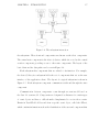
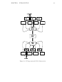
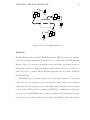
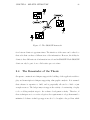
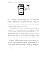
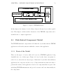
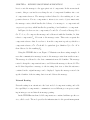
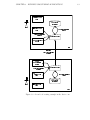
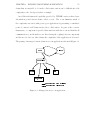
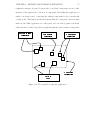
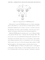
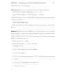
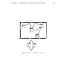
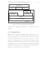
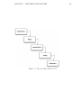
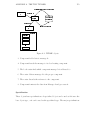
Formally, an application that uses a room is represented as
AP P LICAT ION = {R, C1 , C2 , . . . , CN }
where R is the room application and C1 through CN are parts of the client applications. Each client communicates to the room, and the room communicates to each
client.
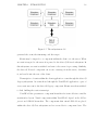
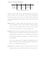
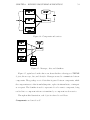
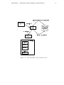
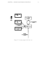
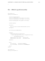
A room-based application defines one message type in addition to the standard
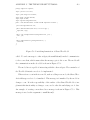
THYME messages. This message, the RoomRegistrationMessage, is shown Definition 23. A client sends the RoomRegistrationMessage to the room upon registering
and unregistering from the room. The room rebroadcasts the RoomRegistrationMessage to currently registered clients.
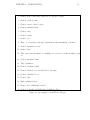
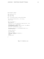
Definition 23 The RoomRegistrationMessage is defined as:
RoomRegistrationMessage = {{CLIENT −DAT A}, REGIST RAT ION −ACT ION}
REGIST RAT ION -ACT ION is chosen from a set {REGIST ER-CLIENT,
UNREGIST ER-CLIENT, CLIENT -HAS-REGIST ERED,
CLIENT -HAS-UNREGIST ERED}.
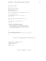
Each room-based application defines their own set of messages to communicate
between clients. The room component is implemented or parameterized to respond
to those messages and selectively pass them to clients.
WYSIWIS groupware that is not replicated exactly is susceptible to externalities
[BSSS01]. An externality arises when the information or presentation accessible to
one party in a collaboration is different than that of another party. The THYME
groupware components presented here do not explicitly address externalities in their
development, but potential externalities are discussed in the component descriptions
below.
CHAPTER 3. BUILDING GROUPWARE APPLICATIONS
80
Chat Room
The chat room application included with THYME, as discussed above, presents an
interface similar to instant messenger [Ame03] or IRC [OR93], which allows users of
the application to communicate textually. The chat is completely unstructured and
open, with no floor control or other restrictions on activity.
In addition to the chat room described above, THYME includes a chat room that
is based around the room component. When a new chat utterance is formulated, a
message is constructed that is sent to the room associated with the chat client. The
room relays the message and the communication is displayed in the incoming communication panel. Like instant messaging, communication is only sent when the user
explicitly sends it; the incoming communication panel is not updated continuously.
Each chat room client component collection is now defined by the components:
{INCOMING-CHAT -V IEW, OUT GOING-CHAT -V IEW, CHAT -MODEL, ROOMCLIENT }
Communication from the OUT GOING-CHAT -V IEW are sent to the room
by the ROOM-CLIENT . Incoming communication is received by the ROOMCLIENT and sent to the CHAT -MODEL. The INCOMING-CHAT -V IEW
is updated from the CHAT -MODEL.
The chat room uses the ChatCommunicationMessage, formally defined in Definition 24.
Definition 24 ChatCommunicationMessage = {{MESSAGE, CLIENT -DAT A}, CHAT COMMUNICAT ION-ACT ION}.
Where CHAT -COMMUNICAT ION-ACT ION is chosen from the set
{COMMUNICAT ION-T O-ROOM}.
CHAPTER 3. BUILDING GROUPWARE APPLICATIONS
81
In the COSI 125 class, discussed in Chapter 6, enhancements were made to the
basic chat room component collection. For example, the ability to “whisper”, or send
communication to one other user, not to everyone in the room, was added. This
feature was implemented by altering the chat communication message to include a
field for the targeted user and altering the room to only rebroadcast the message
to the sending user and targeted user. Also added was the addition of emoticons,
graphical representations of certain text combinations, such as “:)” being interpreted
as a smiley face. This feature was implemented by sub-classing the incoming chat
view component to parse each line of text and insert an icon where appropriate,
replacing the text.
Shared Whiteboard
The shared whiteboard presents a shared surface and set of artifacts that can be
placed and altered on the canvas. The artifacts on the canvas are replicated on all
canvases that are attached to the same room.
The component collection contains two view components, one for the palette of
artifact types and one for the canvas. The palette is populated at run time with the
list of available artifacts and canvas manipulated actions (such as DELETE and SELECT). The canvas responds to mouse actions, based on where the mouse is clicked,
the status of the palette, and the internal status of the canvas. For example, if the
palette has an oval artifact selected, the canvas has nothing selected, and the mouse
action is a click and drag, an oval will start to be drawn. However, the palette has
the SELECT action selected, the mouse is clicked within an already drawn oval and
the mouse action is a click and drag, the already drawn oval will be resized on the
canvas. The basic shared whiteboard is shown in Figure 3.10.
This component collection is a mostly-strict WYSIWIS groupware application.
CHAPTER 3. BUILDING GROUPWARE APPLICATIONS
82
Figure 3.10: The shared whiteboard
All artifacts that are done being drawn are replicated on every canvas’s application.
When an artifact is being drawn or being changed, it is updated at intervals on other
client’s canvases, while being updated continuously on the canvas of the client that
is updating the artifact.
The shared whiteboard adds the SharedWhiteboardArtifactMessage. It is shown
in Definition 25.
Definition 25 SharedW hiteboardArtif actMessage = {{ART IF ACT, CLIENT DAT A}, ART IF ACT -ACT ION}
Where ART IF ACT -ACT ION is one of {MODIF Y, DELET E, CREAT E, CLEAR}.
The shared whiteboard application is defined by the set {ART IF ACT -MODEL,
ART IF ACT -F ACT ORY, CANV AS-V IEW, P ALET T E-V IEW }.
The whiteboard information is, ultimately, positional. The major externality
that this component is vulnerable to involves the size and shape of the whiteboard
dimensions. If one user has a much larger display than another, then some artifacts
may be drawn off-screen of the other user.
CHAPTER 3. BUILDING GROUPWARE APPLICATIONS
83
Shared Browser
The shared web browser presents an interface for collaboratively viewing and interacting with web pages. The displayed web page is a strict WYSIWIS component,
allowing all users to see the same web page. Interaction with the web page and history of visited pages is shared across clients, so clicking on a link on the web page,
choosing a previously visited page, or entering a new URL causes all clients to go
to the selected web page. Often the web browser component is embedded within a
shared scroll pane or co-present scroll pane. The basic shared browser component
collection can be seen in Figure 3.11.
Figure 3.11: The shared browser
This component collection provides three visual components, the shared browser,
a URL entry field, and a toolbar containing a forward and backward button to interact
with the URL history. A shared browser instance is defined by the set {BROW SERV IEW, ENT RY -V IEW, T OOLBAR-V IEW, HIST ORY -MODEL, BROW SER-MODEL}.
CHAPTER 3. BUILDING GROUPWARE APPLICATIONS
84
This component collection also defines a new message, the SharedBrowserMessage.
It is shown in Definition 26.
Definition 26 SharedBrowserMessage = {{URLE NT RY }, BROW SER-ACT ION}
Where BROW SER-ACT ION is chosen from the set {NEW -URL, HIST ORY URL}.
The shared browser is vulnerable to two major sets of externalities. First, if two
users have different size displays, the amount of information shown, and, perhaps, the
layout of that information, will be altered. Second, the current shared web browser
passes URLs, not the web page contents. If one user has certain login information or
“cookies” associated with the web page, the specific information presented to each
user may be different.
Shared Editor
The shared editor provides an interface for collaborative editing of a document. The
document editor is a strict WYSIWIS component, allowing all viewers to see the
same document, with the same information. Edits to the document are immediately
applied to all user’s documents. Like the shared browser, the editor can be embedded
into a co-present or shared scroll pane. The shared editor is shown in Figure 3.12.
The shared editor component collection only includes the editor visual component.
This collection defines a message, the SharedEditorMessage. It is shown in Definition
27.
Definition 27 SharedEditorMessage = {{OF F SET, LENGT H, T EXT }, EDIT ORACT ION}
Where EDIT OR-ACT ION is chosen from the set {INSERT, DELET E}.
CHAPTER 3. BUILDING GROUPWARE APPLICATIONS
85
Figure 3.12: The shared editor
The shared editor does not have a rigourous conflict resolution capabilitity. As is
the default in all THYME applications, actions taken by users are applied in a “first
in, first out” serial ordering. In the case of the shared editor, there is a single, master
model that is used by all participants in a shared editor session, so all actions are
serialized against that model. The resulting effect is that the shared editor buffer
will remain in a consistant state, although there may be social conflicts, such as a
user erasing a section of text as another user is trying to modify it. A mechanism to
better handle such conflicts has been discussed as potential future work.
3.3
Case Study: Building a Groupware System
Using THYME
Given the framework for building groupware and rich library of widgets and components, it is possible to assemble complex groupware applications. This case study
CHAPTER 3. BUILDING GROUPWARE APPLICATIONS
86
discusses how an application can be assembled out of existing components.
The Online Research Assistant (ORA) is a THYME application that was assembled by a group of students in the COSI 125 class discussed in Chapter 6. The goal of
this application was to provide the ability for two or more people to collaboratively
research a topic on the world wide web. As shown in Figure 3.13, there are two major
visual components, the browser on the left and the chat room on the right. The
browser is from the shared web browser component collection, with the BrowserView
being placed inside an instance of the SharedScrollPanel widget and the EntryView
below it. The browser is overlayed in a drawing layer by the CanvasView of the
Shared Whiteboard. The browser and the drawing layer are kept synchronized by
having them both placed in the same SharedScrollPanel. The right side of the screen
is the incoming and outgoing chat views.
Figure 3.13: The ORA application
The assembly of the ORA application is shown in Figure 3.14. While the composite ORA component collection has a production and acceptance set containing
the messages from the chat room, shared whiteboard, and shared browser, each component collection that makes up the ORA application are mostly orthogonal with
each other. They, in fact, overlap only on the room registration message. The room
87
CHAPTER 3. BUILDING GROUPWARE APPLICATIONS
registration message is passed between the room client components and not other
members of the application’s collection of components. In building the application, a
single room client is used, connecting the existing components to the room through
a single point. This minor modification means that the component collections that
make up the ORA application are orthogonal, and can work together reasonably
safely and have a defined dependency graph through any other common components.
[
f
Z
[
\
]
Z
^
_
`
^
a
b
a
Z
Z
^
c
c
b
d
]
e
^
e
]
b
g
^
\
h
i
h
j
^
k
l
b
h
]
^
_
`
^
a
b
a
]
Z
^
_
`
^
a
b
a
]
a
Z
^
c
c
b
d
]
e
^
a
Z
Z
r
m
n
Z
o
^
h
p
^
`
q
b
Figure 3.14: The assembled composite application
^
_
`
c
c
`
e
^
d
c
b
l
d
\
]
]
e
e
]
^
e
b
a
^
a
CHAPTER 3. BUILDING GROUPWARE APPLICATIONS
3.4
88
Conclusions
This chapter presented the features and formalized model of a software foundation
for building groupware applications in the integrated lifecycle model of development.
This model is realized in a reference implementation, presented as the THYME distributed component framework. This framework provides a component model and a
rich set of groupware component libraries. Through a combination of altering existing components, creating new components, and reusing existing components, complex
groupware applications can be built.
The component model is governed by a set of properties. These properties describe the interaction between components. Orthogonality, for example, describes
whether or not components interact with one another in a larger system, partitioning
the application so that the impact of adding, removing or changing a component is
limited. The interaction between components also enables transcription, which will
be discussed in more detail in the next chapter.
The case study presented in this chapter shows how an example application may
be built through assembly of existing components. The ORA system is complex
application that provides same-time / different place interaction over a shared web
browser, a chat room, and a shared marking surface.
By leveraging the existing, component-oriented THYME applications, a companion replay application can be generated to allow replay of the original application’s
transcripts of use. In the next chapter, the SAGE framework will be described, which
provides this capability.
Chapter 4
Observational Analysis of
Groupware Applications
The complexity of software applications can often be ameliorated by providing the
developer with tools that help in development-oriented tasks. For example, JUnit
[jun] provides a framework and set of utilities to do unit testing of Java classes, UML
diagrams [Fow03] provide structural representations of an object-oriented application,
and embedded application documentation shows meaning and intention behind the
source code itself. These tools allow developers to measure, describe, and visualize
properties of the software system.
When looking at groupware applications, visualizing and testing the use of the application becomes as important as visualizing and testing the structure and individual
units of the application. Suchman and Trigg [ST91] showed the need for being able
to collect information about the activity surrounding a collaborative artifact during
its use so that it could be analyzed after the collaboration was completed. To address
this need, they built a customized tool for doing ethnographic analysis of the artifact
and annotating its passage and transformation through the task environment. We
89
CHAPTER 4. OBSERVATIONAL ANALYSIS OF GROUPWARE APPLICATIONS90
have shown that being able to perform online ethnographic analysis of an application
gives a valuable vector of information, allowing redesigns of the artifact to be done
efficiently and correctly [LA02]. In this same paper, the utility of a custom analysis
application was demonstrated, contrasted to analysis limited to an exact copy of the
system, such as in the jRapture [SCFP00] system.
As the complexity of the application, the cost of developer time, and the push
to deploy a project grow, the willingness to spend resources on building complex
and customized utilities to aid in the development of an application will decrease.
Software testing, for example, is a long acknowledged need that if often underfunded
and under-executed [MSBT04] because of the associated expense. Other types of
analysis applications, especially ones that are not part of the classic lifecycle, are no
different. Therefore, using these tools needs to be made as cheap as possible, such
as by leveraging off-the-shelf tools, such as UML editors, building the construction of
unit tests into the everyday development activity, or generating the support tools by
leveraging the existing system architecture. Because of the associated cost of enabling
analysis techniques in an application, this work proposes techniques to do the latter.
This chapter discusses the needs and use of ethnographic analysis applications in
the integrated lifecycle. These techniques are used to collect information from the
collaborative activity of the participants in a groupware session and give an “overthe-shoulder” replay of their activity. It is also used to provide information into other
analysis capabilities. In order to make the use of these techniques cost effective, they
need to by provided as part of the development of the application. To support these
needs, the SAGE framework was constructed. SAGE provides two major technologies,
a component library that supports the replay of collected THYME transcripts and a
tool that generates a SAGE replay application based on a basis THYME application.
The next section shows the use the ethnographic replay tool to study a session of
CHAPTER 4. OBSERVATIONAL ANALYSIS OF GROUPWARE APPLICATIONS91
activity from the Online Research Assistant (ORA) application. Through a demonstration of analysis, the requirements for transcription and replay are discussed in
the section following. How THYME and SAGE implement these capabilities is discussed and formalized and the code generation and assembly features are detailed.
This chapter concludes with some examples of the other analysis capabilities that are
enabled by this approach.
4.1
Online Research Application
The ORA application, which was shown in the previous chapter as an example of a
THYME groupware application has an associated replay capability. Figure 4.1 shows
this replay application, which was built from the ORA application. This application
was generated using the SAGE generator program, described below.
From a comparison of the ORA replay application (Figure 4.1) and the basis
ORA application (Figure 3.13), it is clear that they share a common lineage. The
center replay window is a direct analogue of the ORA client screen, and contains
individual view components that are leveraged completely from the basis application.
The underlying models, however, are similar (as per Definition 4), but not the same
as the basis application models. These models, as described below, are proxied for
by generated SAGE model components that enable forward and backwards playback
of the application’s activity.
4.2
Example Analysis with ORA
We performed data collection and analyses on usage of the initial design of the ORA
application. The analysis is used to direct the further development of the application,
CHAPTER 4. OBSERVATIONAL ANALYSIS OF GROUPWARE APPLICATIONS92
Figure 4.1: The SAGE replay application for the online research application
allowing conclusions to be drawn about how the application is to be used by the enduser. Based on these conclusions, the development directions can be determined with
a large degree of precision and accuracy, responding to the elicited and observed needs
of the community.
In the example analysis shown, two users with the pseudonyms Tom and Jerry,
are using the baseline version of ORA. Jerry is an ORA developer and researcher who
is assisting Tom in finding papers relevant to a specific topic.
Figure 4.1 shows a segment from this analysis session. This analysis has three
major stages:
1. Initial exploration of a university library, that fails because of limitations in the
web browser associated with the ORA application.
CHAPTER 4. OBSERVATIONAL ANALYSIS OF GROUPWARE APPLICATIONS93
2. Transition to another citation database (the Citeseer database) and resynchronization of the user’s common ground
3. Successful completion of the task
The first part of the session starts with the interaction between Tom and Jerry
(taken verbatim from the transcript):
Tom Hi. Can you help me to find articles or books on mutual belief? I am particularly interested in representation and mutual belief. But first the general
concept of mutual belief.
Jerry sure. let’s start in the library.
Tom wait what did you just do??
Through the use of the SAGE replay application, it is shown that this dialogue
corresponds with Jerry going to the library website. The page loading gives no feedback to the user who did not initiate going to the new website. This confusion as
to what Jerry is doing results in a question from Tom, which requires negotiation to
continue the collaboration (e.g., a repair).
The use of the library does not yield any results, and so Jerry then moves on to
the Citeseer website. Again, because of the lack of feedback to Tom as to what the
web browser is doing, the following interchange occurs:
Tom are you there? I can’t see what you are doing.
Jerry we will search through citeseer for the articles, since the library doesn’t have
anything good.
Tom where are you? nothing is happening
CHAPTER 4. OBSERVATIONAL ANALYSIS OF GROUPWARE APPLICATIONS94
Jerry we’re searching through citeseer for articles that contain the words mutual
and belief
Once Tom’s second set of questions have been asked, the state of the replay is
rewound to the web browser event previous to Tom’s question, in order to determine why Tom is not seeing any activity from Jerry’s actions. It is shown that Jerry
attempted to use the library website to search for books, but the web browser component failed to interact with the custom JavaScript on this website. Skipping to the
next web browser event, Jerry switches to the Citeseer website and informs Tom in
the last utterance of this section.
Through the session, a number of desired features are specifically identified. For
example:
Tom can I look at the pdf?
Tom any version of the paper?
Jerry unfortunately, there is no PDF viewer built into this application. We can add
it in a few spirals.
In viewing the activity in the replay tool, a workaround is identified by Tom.
Citeseer can display images of papers, which worked sufficiently for this task.
Another request was made, to allow searching for specific features and subject
matters of papers, which was clearly not within the scope of this tool, and identified
as such during the conversation.
Tom is there a way we can filter for philosophy and not ai papers?
Jerry I do not think citeseer has that capability.
Jerry I don’t think any paper search engine has that capability, currently.
CHAPTER 4. OBSERVATIONAL ANALYSIS OF GROUPWARE APPLICATIONS95
Jerry how can you tell that a paper is philosophy, and not AI?
Based on the observations of use, pointing to the web page and aspects thereof
was done frequently, but the drawing tools, which existed to aid in the referencing
of objects in the web page were not used. Because of how the drawing tools were
implemented, in that they required changing the application’s mode of use from
browsing to drawing, their use may have been too cumbersome. It may also be that
in this collaboration, which had only two users and relatively manageable web pages,
the pointing capabilities were not needed. As the application is used further and
more data is collected, the drawing mechanism will see more use and may need to be
refined.
4.3
Transcription and Replay, Revisited
As discussed in Chapter 2, the capacity to do transcription and replay of groupware
activity is critical to online ethnographic analysis. While touched on previously, it
is necessary to determine the exact requirements that a candidate analysis solution
must possess.
4.3.1
Transcription
Many of the features of a replay tool depend on the quality of the transcript. Online
ethnographic analysis is best supported by a complete transcript, where each state
of the collaboration can be reconstituted. It is important that this transcript be
complete for both user interface and domain actions, as both types of information
can be critical to understanding the collaboration process.
As shown in Table 4.1, the approach taken by THYME and SAGE accomplishes
these requirements. THYME collects information from both user interface and do-
CHAPTER 4. OBSERVATIONAL ANALYSIS OF GROUPWARE APPLICATIONS96
main actions by collecting messages as they are used within the application during
run-time. The messages are used to reconstruct the state of the collaboration as an
additive process.
Application
jRapture
Playback
TimeWarp
Videotape
THYME and SAGE
Complete
UI
UI
domain
none
both
Info Type
UI
UI
domain
N/A
both
Transitions
transitions
transitions
transitions
states
transitions
Off-line
none
none
none
video
none
Table 4.1: Transcription features
4.3.2
Replay
The replay aspect of online ethnographic analysis processes the transcript so that
the analyst can view the collaborative activity from a similar perspective to the users
who generated the transcript. The features of the tool that enable the replay partially
depend on the qualities of the transcript, such as the information encoded and the
completeness of this information.
Capabilities such as searching require certain levels of completion in the transcript. The ability to search for specific types of activity also requires enough information available in the transcript to identify the desired activity. The combination
of THYME and SAGE, as discussed, provide the feature set necessary to do the level
of replay necessary for analysis. The comparison of the THYME and SAGE solution,
compared with other approaches discussed in Chapter 2, is shown in Table 4.2.
CHAPTER 4. OBSERVATIONAL ANALYSIS OF GROUPWARE APPLICATIONS97
Application
jRapture
Playback
CollabLogger
Videotape
THYME and SAGE
Search
No
No
No
No
Yes
Precision
time, ui
time, ui
none
time
time, ui, domain
Annotation
none
none
none
yes
yes
Aggregate Information
none
none
yes
none
none
Table 4.2: Playback features
4.4
Supporting Online Ethnographic Analysis Using THYME and SAGE
The combination of the THYME groupware framework and the SAGE class library
provides a reference implementation of the transcription and replay capabilities that
support the requirements of replay described above. A SAGE replay application
appears similar to the basis application it is replaying. The most straightforward
SAGE application, in fact, should look identical to the basis application with the
addition of the replay controller. Further customizations are possible, allowing the
application to be more useful in the analysis of the activity.
A THYME application is natively equipped to collect a transcript of usage. A
transcript exists for each node in the application, and consists of a set of THYME
messages. Because the messages are timestamped, a node can be played back individually or a set of nodes can have their transcripts merged together and a set of nodes
can be replayed as one replay session. The remainder of this section discusses how
THYME and SAGE enable transcription and replay, implementing the requirements
discussed above.
CHAPTER 4. OBSERVATIONAL ANALYSIS OF GROUPWARE APPLICATIONS98
4.4.1
Transcription
As stated in Chapter 3, a THYME application is defined by a set of components
and the connections between them. Components are grouped into structures called
nodes, each of which has its own namespace. Components communicate via a pernode component called the message router. A component sends an addressed message
to the message router. The message router will find the component the message is
addressed to and deliver it.
THYME’s message-oriented architecture has several useful consequences for collecting a transcript of use:
1. All communication between components happens through messages, so a THYME
application needs to only collect messages in order to generate a complete transcript.
2. Since all messages go through routing components, only the message routers
need to be accessed in order to record all the messages.
To collect the usage transcript for an application, the message routers collect all
messages at their point of origin, defined as the first message router that handles the
message. This approach ensures that every message is logged once and only once. As
a router collects messages, it sends the message to the transcript collector component.
This component will store all messages it receives, thereby building the transcript.
This component forms a unified interface to the transcription subsystem, abstracting
the means by which the transcript is stored and reconstructed and allowing different
transcription formats and strategies to be used without changing the application.
Figure 4.2 illustrates the interaction of a THYME application with the transcription
subsystem.
CHAPTER 4. OBSERVATIONAL ANALYSIS OF GROUPWARE APPLICATIONS99
Figure 4.2: Logging messages in a THYME application
Each transcribed event in the THYME framework is stored with two timestamps,
when it is first handled by a router and when it is actually transcribed. The two
timestamps give sufficient data for clock skew correction to be performed, if necessary.
The timestamp is the discrete points in the timeline of the session and is used to
explicitly order messages as they get injected into the playback application.
Within the THYME application, transcripts can be accessed during the run-time
of the application through a service component called the transcript emitter. This
service provides access to previously transcribed messages in the current session of use.
A transcript is ended when the session of use is over and archived so that it includes
session summary information (called meta information) as well as the transcript.
Archived sessions of use can be loaded into the transcript emitter explicitly. A SAGE
application makes use of the transcript emitter to playback archived sessions.
In a THYME application, all changes to the application state occur through the
reception and processing of messages. A complete transcript is, therefore, the collection of all messages that are sent between components. A transcript is represented
CHAPTER 4. OBSERVATIONAL ANALYSIS OF GROUPWARE APPLICATIONS100
as T RANSCRIP TT ∈[X,Y ] and represents the transcript for all messages between MX
and MY inclusive. T RANSCRIP T (X) is used for referring to the message MX that
is stored in the transcript.
Given that a transcript is a collection of messages that is sent throughout the
application, a transcript can be shown to be complete if it captures all interaction
throughout the application. The set of messages captured in a transcript during the
runtime of an application a is represented as T RANSCRIP Ta . If each instant of
change that occurred during the runtime of a is contained in T RANSCRIP Ta , then
T RANSCRIP Ta is a complete transcript of the runtime of a.
The transcript collects into a transcript containing both interface events and domain actions. Interface events can be encapsulated as messages to an interface controller and thereby are collectable in the transcript. Because messages between components are encoded in terms of the representation system of the application, the
information contained in the message includes domain action information. For example, a message passed from one client’s chat room component to another client’s chat
room component contains information that the message is a chat message. Thus,
during replay, the analyst can run the replay until it comes to a chat message. Alternately, if users are collaboratively constructing a plan in a shared window, messages
between client planning components will contain information that enable the precise
replay of planning actions.
4.4.2
Replay
Replay of a transcript is enabled by the SAGE component library. It provides access
to the collected transcript and enables a replay application to build a complete state
of the basis application at a precise level of individual messages.
Given a basis application A and a collected transcript T of size S replaying T
CHAPTER 4. OBSERVATIONAL ANALYSIS OF GROUPWARE APPLICATIONS101
on A is done by applying the elements of the transcript on each component in the
application. This is done as follows:
REP LAY (A, T, 0, S) =
(∀i : 0 ≤ i ≤ S; Ai = Ai−1 + T RANSCRIP T (i))
Where the statement Ai = Ai−1 + T RANSCRIP T (i) is expanded to
Ai−1 + T RANSCRIP T (i) = (∀C : C ∈ Ai−1 ; C = C(T RANSCRIP T (i)))
Replay to a specific message X is done by applying all positionally previous events
from the transcript, up to and including MX , to the application.
SAGE provides event-level precision. Time-level precision within a collected transcript is limited to the instants of time that are collected in the transcript. While
each message has an associated timestamp that refers to when it was collected, the
granularity is limited to the points in time when the messages were actually collected.
For example, if the time between an event i − 1 and i is 10 minutes, there is no way to
display any activity between those two events. However, if the transcript is complete,
it is possible to go to a specific point in time by progressing to the messages the
last message that occurred before the requested timestamp. If, in the example given,
the transcript is complete, it can be deduced that no system activity occurred in the
intervening 10 minutes, so there is no real precision lost.
Supporting event-level precision occurs by being able to search for specific types
of events. Given a transcript, the set of possible event types is represented by the
set EV ENT -T Y P ES(T ), where T is a transcript. The available set of EV ENT T Y P ES is related to the level of domain information in the transcript. If the transcript only contains UI events at the level of keyboard and mouse actions, then that
level of granularity is available to the analyst through the replay tool. However, if
the transcript contains events that illustrate interaction with the representation system, such as Chat Messages, then the replay tool can use those events to show event
CHAPTER 4. OBSERVATIONAL ANALYSIS OF GROUPWARE APPLICATIONS102
boundaries. This information would allow the analyst to say “skip to the next chat
utterance”, for example.
Milestoning
The approach of encoding transitions between states is done for two major reasons.
First, encoding the entire state at each change will take up a large amount of disk
and processing resources and, second, will require a level of introspection and access
to all aspects of the application that may not be easily available. Instead, encoding
transitions is accomplished through the use of the existing message passing infrastructure, without needing information about the components, their state, and how
their state can be captured.
In encoding transitions, the ideal situation would have each transition be reversible. That is, CT =i = CT =i−1 +Mi and CT =i−1 = CT =i −Mi . However, messages in
our framework, as is true in the majority of message-passing frameworks, are not designed to be reversible, as doing so puts a large burden on the developer to track state
and limit actions on the application data. Without reversible messages, actions such
as rewinding an application’s state are difficult. A brute force example of rewinding
state could consist of selecting the desired point in the transcript, resetting the application and applying all messages up to the newly desired timestamp. Early versions
of SAGE provided such a mechanism, which was quickly deemed unsatisfactory.
Since the data that makes up a THYME application is stored in components, to
implement a proper rewinding mechanism for a transcript requires each component
to be capable of rewinding its state. To accomplish rewind across all types of components, SAGE provides a set of component wrappers, based on a design pattern called
mementos [GHJV95]. A wrapper’s internal state is actually a collection of milestones,
which are indexed instances of the component it is wrapping. Each index refers to a
CHAPTER 4. OBSERVATIONAL ANALYSIS OF GROUPWARE APPLICATIONS103
specific message number in the transcript. Milestones are laid out so that to retrieve
an instance that corresponds to a timestamp previous to the current one, it is only
necessary to find the milestone that is closest to, but previous to, the desired timestamp. The components at that milestone are then copied ,and any messages that
exist between the desired timestamp and the current component set’s timestamp are
retrieved and applied. This process is shown in Definition 28.
Definition 28 Given a component wrapper CW that wraps a component type C,
upon receiving message M, which is position I in transcript T , the following takes
place:
1. if there is a milestone MI in CW that corresponds to CT =I , activate that milestone and exit
2. if there is no such milestone, find the milestone MIJ that has the closest index
less than I
3. copy MIJ to a new component CT =I
4. apply every message MX where X > J ≥ I to CT =I
5. activate CT =I
6. if a new milestone is desired at I, store CT = I into a milestone MII
The decision to store milestones depends on the application and storage needs.
The milestone process is related to checkpointing [Lor77] a database to ensure consistency of the database state. Milestones may, unlike checkpoints, change in number
and temporal location during execution. Global system snapshots [CL85] [YM92], a
technique used in distributed debugging, is also similar, in that it looks to collect a
CHAPTER 4. OBSERVATIONAL ANALYSIS OF GROUPWARE APPLICATIONS104
consistent state across multiple systems. The milestones described here are not used
to create a unified system state, although they do that as a consequence because
of the simple nature of the SAGE application. Instead, milestones are designed to
provide an accessor for a set of temporal positions within a single model.
A component can implement its own state mechanisms so that it can provide
its own reverse functionality. The wrapper approach is a general solution if the
component does not have this capability already.
Analysis Interface
Using the replay application, an analyst can perform precise analysis of the usage of
the basis application. The SAGE Playback Controller (shown in Figure 4.3) gives the
analyst control over the flow of the playback of the transcript. The playback controller
has standard VCR-like controls: play, rewind, fast forward, and stop (callout 1 in the
figure). The controller adds two other standard movement controls: step forward
and step back, which move one event forwards and backwards, respectively. The
controller also allows movement through the transcript by searching for types of
messages that are in the transcript’s set of EV ENT -T Y P ES (callout 3). The list
of types is populated from the transcript at the run-time of the replay application.
(Note that the message displayed in this example is the Shared Browser message, more
meaningful event names will be available in a future version of the replay application.)
The controller also provides the analyst feedback as to where he is in the session. The information underneath the VCR controls (callout 2) shows the current
timestamp of the session, based on the timestamp of the last event replayed. This
number may be the standard Unix milliseconds-since-epoch, or a more traditional
format, showing time and date. Next to the time display is the current message and
the total number of events in the session. Movement within the session can also be
CHAPTER 4. OBSERVATIONAL ANALYSIS OF GROUPWARE APPLICATIONS105
Figure 4.3: SAGE playback controller
controlled via a slider (callout 4), at the bottom of the window. The slider provides
feedback as to where in the session the current timestamp is, with the far left of the
slider being the beginning of the session and the far right being the end. The analyst
can manipulate the slider, causing the playback tool to go to the event closest to the
timestamp selected.
4.5
Generating the Replay Application
Building a replay application as a custom application for each basis application is an
impossible strategy. As development budgets are reduced, any significant investment
in building tools is likely to be cut outright. However, if these applications could be
generated, it still provides a basis for further customization, then the tools may be
available at a greatly reduced cost, especially for the benefits demonstrated previously.
Given a basis groupware application, the goal is to generate a replay application
CHAPTER 4. OBSERVATIONAL ANALYSIS OF GROUPWARE APPLICATIONS106
based on the components and structure of the basis application. Formally, the replay application is a combination of the basis application and the replay application
component framework, as shown in Definition 29.
Definition 29 A replay application for an application A is defined as:
REP LAY -AP P LICAT IONSA ∈ {BASIS-AP P LICAT IONA, REP LAY -AP P LICAT IONF RAMEW ORK}
The generation of the application is done by selecting the aspects of the basis
application that are to be replayed. The actual selection is done through the SAGE
application generator, shown in Figure 4.4.
Figure 4.4: The SAGE application generator
Determining how to leverage the basis application components relies on being
able to identify the components, their properties, and their use within the application. Some of these capabilities can be determined from the application structure,
such as the acceptance and production sets. Other information, such as the use of a
component as a model, needs to be explicitly identified. THYME provides a mecha-
CHAPTER 4. OBSERVATIONAL ANALYSIS OF GROUPWARE APPLICATIONS107
nism to instrument the application structure to determine how the components place
within the application structure.
Leveraging a basis component is not always possible to do without modification.
How possible it is to use a component unmodified depends on several factors, but is
mostly indicated by its adherence to strict WYSIWIS principles, as shown in Figure
4.5. As a component diverges from strict WYSIWIS, it no longer has the same displayed content for every user. For example, the outgoing chat view is not WYSIWIS.
If it were needed to see every character typed in that component by every user, the
component would need to be reimplemented for its use within the replay application.
~

z
…
w
ƒ
u
‚
†
|
ƒ
ƒ
u
~
„
t
v
…
‡
ˆ
‰
Š

Œ
Š
•
‹
Œ
‹
–

Œ
Ž
‘
Ž


—
Š

’
‹
™
‘
Ž
’
—
‹
Ž
‘
‰
Š
Œ
Œ
Ž

“
Š
š
”
ˆ
‰
Š

Œ

•
‹
Ž
–

Œ
Š

—
‹
‹
‘
“
’

‹
˜
‘

‰
‰
Œ
Œ
Ž

‹
“
Š
”
ˆ
‰
Š
Š

Œ
‹
•
Œ

‹
–
Ž
Œ

—
Š
‹

‹
“
‘

˜
’

‹
‰
‘
Œ
‰

‹
Œ
Ž
“
Š
”
s
t
u
v
w
t
x
y
s
z
x
z
s
{
|
}
~

|
€
x
y
s
z
x
z
s
Figure 4.5: Leveraging a basis component in generation of the replay application
4.5.1
Instrumentation of THYME
The replay application generation depends on being able to interpret the structure
of the basis application so that its existing components can be found and reused. In
order to perform this task, it is necessary for enough standardized structure to exist
within the basis application for the application generator to use. THYME provides a
CHAPTER 4. OBSERVATIONAL ANALYSIS OF GROUPWARE APPLICATIONS108
number of instrumentation hooks that the developer can use to make the structure of
the application, and purpose of the components, apparent. The two major methods
of identifying this information are capabilities and roles.
Capabilities
The first type of instrumentation occurs through the use of a tagging interface, called
a capability. This interface describes a component as having the responsibility of performing a certain type of function within the context of the larger application. Each
grouping of components, including widgets, component collections, and applications
can define sets of capabilities for developers to use.
Capabilities represent the encapsulation of the component function. Often a basis
application will extend or otherwise alter components in a component set. By using
capabilities, the intent of the component is preserved. Leveraging the existing intent
structure of the already-known components allows already established tools to be used
without change. For example, in the Workforce application (discussed in Chapter
7), the palette component from the Shared Whiteboard application was extensively
changed to allow for the separation of different artifact types, yet it still used the
Artifact Palette capability. By retaining the capability, any existing custom SAGE
framework components that already use an Artifact Palette component can leverage
this part of the Workforce application structure without change.
Roles
Design patterns [GHJV95] provide recurrent solutions to common development scenarios found in the design and implementation of object-oriented (and componentoriented) applications. They are well-known, well-tested, and well-used structures
that document uses and scenarios of use. Through the use of design patterns, devel-
CHAPTER 4. OBSERVATIONAL ANALYSIS OF GROUPWARE APPLICATIONS109
opers leverage a history of use of the pattern, knowing that it has been refined and
that the next generation of developers will understand the code structure and the
intent behind the code structure.
Design patterns are useful in the context of putting structure and instrumentation
in the design of the application for the same reasons that they are useful for embedding
knowledge within the application structure for future developers. In order to explicitly
embed these patterns in the application, THYME provides a set of tagging interfaces,
called roles.
Roles provide a way for the developer to explicitly tag what patterns a component
is involved in and what the component does within the pattern. For example, the
most common pattern used in THYME is the Model-View-Controller (MVC) pattern
(also applicable to the similar Observer pattern) and an extension of this pattern that
adds an authoritative store role (S-MVC). THYME defines four role interfaces, Store,
Model, View, and Controller that are implemented by components that participate
in this pattern. These roles explicitly define the pattern and designate how each
component is used in this pattern. In the replay application, for example, models
and views are extracted from the basis application and used by the application for
accepting data from the transcript and displaying the interaction, respectively.
4.5.2
Assembly of the SAGE Application
Assembly of a SAGE application occurs via a transformation of a THYME application. The transformation operates on an application Ap and will produce a new
application Asage . From the application Ap , two sets of components can be extracted,
the models (Mp ) and the views (Vp ), which correspond to those components in the
application that identify themselves as models and views, respectively. This transformation occurs in three steps.
CHAPTER 4. OBSERVATIONAL ANALYSIS OF GROUPWARE APPLICATIONS110
In the first step, each model in Mp is transformed into a model that can process
the SAGE replay messages. In the common case, models can be wrapped by SAGE
model wrappers. The most common type of wrapper assumes that the model can be
manipulated completely by messages and can be cloned. If these two requirements
hold true, the model can be used for replay in both the forward and reverse directions
without any modification. In cases where a model cannot be wrapped, a new model
or custom wrapper needs to be implemented which can accept the SAGE replay
messages. This situation is uncommon, however. This new set of SAGE models is
referred to as Msage .
The second step identifies the set of views that are part of Ap . Views that depend
on models do not need to be changed, they will continue to pull the data from the
models and be updated appropriately. In this step, however, views can be added or
replaced by the developer, if desired. For example, in a replay tool the view that
corresponds to a relaxed-WYSIWIS view may be replaced with one that provides an
omniscient view of the activity. The new set of views is called Vsage .
In the last step, the replay application is constructed. SAGE provides a set of
components, SAGE-REP LAY that are used in the replay of applications. These
components provide the means for moving forwards and backwards in the timestream
that is exposed by a transcription and getting the messages to the components for
which it is replaying. The new SAGE application, Asage , is the set of components
{Vs , Ms , SAGE-REP LAY }.
The generated application performs two functions. The first is to pre-process the
transcript to be played back. This pre-processed transcript (T RANSCRIP Tpp) is a
strict subset of the original transcript. In this subset all events that are not directly
accepted by the playback application’s models are eliminated from the transcript. The
result is a transcript that contains no secondary messages, such as those generated
CHAPTER 4. OBSERVATIONAL ANALYSIS OF GROUPWARE APPLICATIONS111
• 7. tug1: mX at 400 125 [IOTA-7 waste: mx@400,125]
• 8. crane1: medium at 392 127 [IOTA-8 waste: m?@392,127]
• 9. crane1: that’s got to be the same one [IOTA-9 repair: IOTA-8=IOTA-7]
• 10. tug1: yep IOTA-9
• 11. tug1: that’s an mX [IOTA-7 waste: mx@392,127]
Figure 4.6: A sample discourse tagging
by models in response to external input. This transcript is complete with respect to
the granularity that the playback application is capable of showing. Combined with
the timestamp ordering of the transcript, many of the non-deterministic concerns
expressed by Ronsse, et. al. [RDC+ 03] are eliminated.
4.6
Other Visualization Techniques
One application of the transcription of THYME applications is called Lyze, built
by Alexander Feinman, for analyzing the structure of the discourse of collaboration.
Lyze uses the SAGE framework to extract the discourse from a collaborative session’s
transcript. The discourse is fed into the Lyze discourse tagger, which an analyst then
uses to tag the referential structure of the collaboration. These tags describe the
information flow between the users of the application. Each piece of information is
called an iota. An example tagging can be seen in Figure 4.6.
The information contained in the tagging of the discourse provides another set of
data that can be used by an analyst. Lyze provides two visualization tools to show
the lifetime and grouping of the transcript iotas. The first tool shows the lifespan of
each iota as a line. The lengths of the life span of each iota can be compared, allowing
a visual comparison. Each mention of the iota results in another point being drawn
CHAPTER 4. OBSERVATIONAL ANALYSIS OF GROUPWARE APPLICATIONS112
on the iota line. This tool is shown in Figure 4.7.
Figure 4.7: Life span tool
The second tool provides a scatter graph of all iotas in the transcript. This graph
shows the number of mentions of an iota on the X-axis and the life span of the iota on
the Y-axis. Iotas that are visually clustered together may indicate similarity between
a set of iotas.
Both of these tools are covered in more detail in another work [FA03].
4.7
Conclusions
This chapter discussed the use and implementation of the customized replay application supported by the SAGE component library and application generation tools.
This application fulfills a key need in the building and testing of groupware applications by allowing the analysis of how the application is used during a collaborative
session.
In showing the need of this capability, the problem of how to build such applications where few extra resources are available needs to be addressed. A methodology
for generating these applications was detailed, which greatly reduces and, in some
CHAPTER 4. OBSERVATIONAL ANALYSIS OF GROUPWARE APPLICATIONS113
cases, eliminates the cost of constructing the replay application.
This chapter also presents the instrumentation and transcription techniques that
are part of the THYME framework. Structural instrumentation allows meaningful
manipulation of a THYME application. Transcription provides the record of the
application usage that the SAGE application can replay.
In the next chapter, how THYME has been used in the class room is discussed.
One example Human-Computer Interaction class taught at Brandeis University used
THYME to build their term projects. Their experiences provide evidence of how
THYME can be used with great success in the rapid development of analyzable groupware applications.
Chapter 5
Distributing Computing
Applications
The two previous chapters have discussed the THYME component model, the groupware component libraries, and how the component model can be manipulated to
construct the replay application. Groupware applications are, at their core, distributed applications. Whereas the THYME framework provides support for building
groupware applications, it also provides a library that aids in the construction of distributed applications. These capabilities are subsumed into the THYME groupware
framework, and are identified as the THYME Component Collection in Figure 3.3.
These components displace the complexities of building distributed applications by
providing components that handle the common functions that these applications depend on, such as discovery, multi-component routing, and transcription across nodes.
They take advantage of the properties of network routing, as discussed in Chapter 3,
but work completely within the boundaries of the THYME component model.
114
CHAPTER 5. DISTRIBUTING COMPUTING APPLICATIONS
5.1
115
Multi-Component Routing
The THYME network routing model provides the means to deliver a message to a set
of components, so long as the identifier that is associated with those components is
known. If the routing pattern is simple, in that it is one component to a set of known
components, the provided model is sufficient. If the pattern is more complex, such
as a publish-and-subscribe pattern where the publishing component does not have
visibility into the subscribed components, the basic routing model will not work.
The THYME component collection introduces a new component called a bus,
which is multi-point routing technique [Micb] [UM99]. The bus provides two routing
features unavailable through the traditional routing model. First, the sending component does not need to have awareness of the set of component identifiers that are
receiving the message. The bus knows the component identifiers, or knows how to get
them, the sending component does not. This feature allows components to subscribe
to a channel of information, possibly being populated by multiple publishing components. Normally the publishing components would need visibility of every subscribing
component, violating the encapsulation promised by the subscription to a channel.
Second, the delivery of messages via a bus can have conditional rules associated
with it. For example, in the circuit bus, described below, depending on the position
in the bus of the sending component, a specific set of components will receive the
message. If a message is sent by a component in a different position, a different set
of components will receive the message.
The bus component holds a set of component identifiers. When the bus component
receives a message, it will, based on the routing rules contained within the bus, select
a subset of its contained identifiers that will receive the message. The bus is defined in
Definition 30. Two example buses, the circuit-bus and the broadcast-bus are described
CHAPTER 5. DISTRIBUTING COMPUTING APPLICATIONS
116
in Definition 31 and 32, respectively.
Definition 30 Given a bus component B, B has the following properties:
CONT AINED-IDENT IF IERS(B) = {I1 , I2 , . . . , IN }
ROUT ING-RULES(B) = {RULE1 , RULE2 , . . . , RULEN }
When B receives a message, it will attempt to apply each routing rule in sequence.
A rule has a signature of:
ROUT ING-RULE(B, I, M)
Where B is the bus, I is the identifier of the sending component, and M is the
message.
Definition 31 The circuit bus [NGT92] is a bus that contains a set of numeric,
ordered categories in which each contained identifier is placed. A category can hold
multiple identifiers. To send a message to a circuit bus, that sending component must
already be a subscriber to the bus.
The routing rules are as follows:
ROUT ING-RULEScircuit−bus (B) = {RULE1 }
RULE1 (B, I, M) = {
1. set C = the category of the sending identifier
2. if C is invalid, return
3. C 0 = the category succeeding C, where if C is the last category, C 0 is the first
category
4. D is the set of all identifiers in the category C 0
5. route M to the set D
}
CHAPTER 5. DISTRIBUTING COMPUTING APPLICATIONS
117
Definition 32 The broadcast bus is a bus that redistributes a message to all constituent components. The broadcast bus can optionally rebroadcast the message to the
sending component.
The routing rules are as follows:
ROUT ING-RULESbroadcast−bus (B) = {RULE1 , RULE2 }
RULE1 (B, I, M) = {
1. set C = CONT AINED-IDENT IF IERS(B) − {I}
2. route M to the set C
}
RULE2 (B, I, M) = {
1. if the broadcast bus is set to rebroadcast to the sender, route M to I
}
5.2
Discovery
An assembler of a THYME application may not know the components (and their
identifiers) prior to the complete assembly of the application. This situation may
arise for several reasons. The set of components that may be part of the application
are not known ahead of time because the components that are part of the application
depend on external conditions. A client application may also need to find services on
the network, such as other collaborators, without knowing who is part of the collaboration a priori. This case is especially relevant in distributed, multi-user environments
where different clients connect to form the complete application session. Further, the
dynamic nature of THYME applications means that new components may be introduced during the run-time, where the existence of these components could not be
CHAPTER 5. DISTRIBUTING COMPUTING APPLICATIONS
118
known prior to their introduction into the application. Due to these factors, it is
necessary for there to be a facility to discover components during the runtime of an
application.
Discovery involves obtaining a set of component identifiers that map to components that fit a specified discovery profile. The discovery profile contains fields that
specify properties of a component, such as name, capability (as described in Chapter
4), acceptance and production sets, and other semi-structured information that can
be defined as part of the component. A service, called the finder, takes the profile
from the requesting component and returns the set of identifiers. This process is
described in Definition 33.
Definition 33 A discovery profile is described as DISCOV ERY -P ROF ILE =
{F IELD1 = V ALUE1 , F IELD2 = V ALUE2 , . . . , F IELDN = V ALUEN }.
Each component has an associated profile described as COMP ONENT -P ROF ILE =
{F IELD1 = V ALUE1 , F IELD2 = V ALUE2 , . . . , F IELDN = V ALUEN }.
The discovery process for some DISCOV ERY -P ROF ILE DP , run on some
composite component COMP OSIT E,
DISCOV ER(DP, COMP OSIT E) = {∀C I : CI ∈ COMP OSIT E; ∀{F IELD,V ALU E} :
{F IELD, V ALUE} ∈ COMP ONENT -P ROF ILERESOLV E(CI) , {F IELD, V ALUE} ∈
DP }
and returns the set of component identifiers whose resolved component’s component
profile have matching values for the fields that both the discovery and component profile
contain.
In the networked THYME application, the set of components that can be discovered is the set of all components on all nodes that are associated with the application.
This discovery process involves searching all nodes that are within the node neigh-
CHAPTER 5. DISTRIBUTING COMPUTING APPLICATIONS
119
borhood of the application. The node neighborhood is a graph that represents a node
and the connections it has to other nodes. Connections to other nodes are created
when a message router is told to send a message to a component in a different node.
This connection is established and kept open, with each node accepting the other
node into its neighborhood. If there are nodes that are likely to be in communication
during the application session, connections between nodes can be established on start
up of the application. For example, in a room-based application, clients come on line
with connections already established to the room.
The node neighborhood for some node N is represented by NN N , and is a set of
nodes. A sample node neighborhood for an example node A is represented by the
dashed box in Figure 5.1. Directed lines represent a message that was sent from one
node to another. Note that since node E and node F have not sent or received a
message from any node in A’s neighborhood, they are not part of the neighborhood.
THYME also provides a way for nodes to make themselves known prior to an
explicit connection being made through the message router. A service, called the
node registrar, can be used by a node to register its existence. A node can request
the set of registered nodes from the registrar, and use this list to populate its node
neighborhood.
The complete discovery process is shown in Definition 34.
Definition 34 The discovery process for some DISCOV ERY -P ROF ILE DP , being initiated from some node N is described as:
DISCOV ER(DP, N) = {f orallM : M ∈ {NN N, N}; DISCOV ER(DP, Ncomponents)}
CHAPTER 5. DISTRIBUTING COMPUTING APPLICATIONS
›
›
œ

œ

ž
ž
¢
Ÿ
›
œ

ž
›
œ

ž
¡
›
œ

£
ž
›
œ

ž
¤
Figure 5.1: The node neighborhood for A
120
CHAPTER 5. DISTRIBUTING COMPUTING APPLICATIONS
5.3
121
Transcription Support
Transcription needs to exist at all levels of the infrastructure to be effective. One
major area of transcription that is not covered by the message-passing architecture
is the collection of information from non-component sources, such as user interface
widgets.
A service, called the widget factory provides infrastructure for building user interface objects in a THYME application that produce transcripts of their use. These
objects are constructed through the factory [GHJV95] pattern. All objects created by
this service are instrumented so that their actions create a WidgetTranscriptMessage.
This message is informational only and is placed in the transcript of use.
A second consequence of the widget factory allows user interface widgets to be
transparently replaced by shared implementations of the same widget type. Shared
widgets will, in many cases, have the same behavior as the unshared version, from the
perspective of the local user. New shared versions can be added to the widget factory
as they become available without adding any additional code in the application itself.
If both a shared and unshared version of a widget exist, which type of widget is
returned by the widget factory can be chosen at run-time.
5.4
Conclusion
The THYME component collection provides capabilities that aid in the construction
of complex distributed applications. Buses provide additional loose coupling techniques to allow interaction with channels of information, instead of the components
themselves. Discovery allows components to be interacted with by their properties
and capabilities, instead of the specific type of component. It also allows the application to be assembled at run-time, based on the needs of the application and
CHAPTER 5. DISTRIBUTING COMPUTING APPLICATIONS
122
application clients. Finally, techniques such as the widget factory give additional
support to the transcription capabilities of the THYME framework.
In the next chapter, THYME and SAGE are shown in use, as they were used in
a Human-Computer Interaction class, taught at Brandeis University.
5.5
Version
Id : distributed − computing − components.tex2792005 − 11 − 1602 : 49 : 40Zseth
Chapter 6
Use of THYME in the Classroom
As the online ethnographic analysis concepts matured, it became necessary to explore
whether or not the rapid development, redevelopment, and transcript capabilities
could be used by non-experts. As a way of testing these capabilities, in the Fall of
2002, a Human-Computer Interaction (HCI) class held at Brandeis University used
the THYME framework to implement their term projects, which called for them
to implement synchronous groupware applications. In analyzing how the class used
the framework, conclusions can be drawn pertaining to how quickly the distributed
component model can be learned, how efficiently it can be used, and how well the
groupware technology behind THYME can be translated into actual use.
The HCI class is an upper-level class taught in the Computer Science department
at Brandeis University. It was attended by all levels of students, from Freshmen to
Masters, with the majority being Junior or Senior level undergraduate students. The
majority, but not all, of the students were enrolled in the Computer Science major
or minor degree programs. A significant minority of the students had no experience
programming in Java.
This chapter discusses how the THYME framework described in previous chapters
123
CHAPTER 6. USE OF THYME IN THE CLASSROOM
124
was used by the class. The parameters of their assignment are discussed and the types
of systems they constructed within those parameters are described. This chapter
concludes with lessons learned from how the class used the THYME framework,
including where they ran into difficulties and where they were successful.
6.1
The Term Project
The class term project required teams of students to implement a same-time /
different-place groupware application. The class was divided into teams of three or
four students. There were fourteen teams in total. At the beginning of the semester,
a schedule was given, shown in Figure 6.1. One feature of this schedule is that the
class had only 28 days to implement their projects. A key point is that the students
designed their system without any knowledge of the THYME framework, sample
THYME applications, or any knowledge of the THYME capabilities.
During the prototype implementation stage, the class was given access to the
THYME framework, the Shared Whiteboard, and the Chat Room. They had access
to both the class library and the source code. They were also given a template project,
a simple THYME application that showed how to embed both the shared whiteboard
and chat room components in a single application.
Of the fourteen teams, twelve teams completed applications that were able to be
tested. A usable application was defined as one that was sufficient to obtain user
feedback regarding its appropriateness to the task and generate a transcript of use.
As a point of comparison, a similar class was taught in the Fall semester of 1999,
when the THYME framework was not available, but some sample groupware code
was distributed. In this previous class, the teams were given 49 days to implement
their applications, 21 more days than the 2002 class. Nevertheless, the previous class
CHAPTER 6. USE OF THYME IN THE CLASSROOM
125
14 days Description of system, users and tasks. This task required the teams to
interview some sample users of their proposed application and design sample
scenarios of the application’s use.
21 days Initial design. In this task the teams designed the interface, presented story
boards of its use, and performed a GOMS [JK96] analysis of a subset of the
proposed interface. The interface was also presented to sample users to get their
comments and impressions. During this period, the class did not have access to
THYME or its capabilities.
28 days Prototype implementation. At the beginning of this period, the THYME
manual [Lan02] (included as Appendix A), initial instruction, and source code
was given out. The THYME source code included the complete implementation of the THYME framework and implementations of sample applications that
showed how the components could be combined into working groupware applications. The class did not have access to the THYME framework before this
period. In addition to a working prototype, the teams produced user documentation for their applications. During this time period, three teaching assistants
held approximately six hours per week of office hours, which were used by some,
but not all, teams.
21 days Usability testing and redesign. This task required the teams to have their
user population make use of the application. The teams collected transcripts
of these sessions, which were later analyzed to identify areas of problematic
coordination. This analysis led to a proposal document that described how the
application could be changed to overcome collaboration problems encountered
in testing.
Figure 6.1: Term project schedule
had significantly fewer usable applications, roughly half of the teams in that class
produced usable applications.
6.2
Resulting Projects
Each project implemented by the Fall 2002 class showcases some of the different types
of applications that can be constructed using THYME. This section details a subset
of the implemented projects and how the framework was used to implement their
CHAPTER 6. USE OF THYME IN THE CLASSROOM
126
groupware design.
6.2.1
ORA
The Online Research Assistant is an application that allows a more experienced
researcher (such as a librarian) to help another researcher locate information on the
World Wide Web.
This application was built using the shared whiteboard, chat room, and shared
browser sub-applications and made use of the shared scrollpane widget. The shared
whiteboard was modified to be used as a glass pane on top of the browser. The
browser and glass pane were put inside of a shared scrollpane. The chat room was
modified to color the text similar to how the shared whiteboard text was colored and
show “emoticons” in the incoming chat view. No new messages were added. All these
changes were cosmetic, altering properties of the components, but not altering their
interaction.
An example of this application in use can be seen in Figure 6.2. In this example
interaction, two users are collaboratively working to find a specific reference using the
ORA tool. Through the use of the overlaid shared whiteboard, the collaborator who
found the appropriate reference can direct the other participant to it.
The ORA client application is defined by the set
{{INCOMING-CHAT -V IEW 0 , OUT GOING-CHAT -V IEW, CHAT MODEL}, SHARED-W HIT EBOARD-COMP ONENT -COLLECT ION, SHAREDBROW SER-COMP ONENT -COLLECT ION}
Where the INCOMING-CHAT -V IEW is a modified version of the original
INCOMING-CHAT -V IEW that supports user-defined colors and emoticons.
CHAPTER 6. USE OF THYME IN THE CLASSROOM
127
Figure 6.2: Screenshot of the online research assistant
6.2.2
SALSA
The Supplementary Academic Learning System - Alpha application provides a way
for an instructor to lecture to geographically distributed students and for those students to interact with the instructor. SALSA added two related concepts to the
THYME framework, floor control [EGR91] [Cla96] and classes of users.
In SALSA there were two different classes of users, the instructor and the student.
The instructor had complete control over the floor control of the system. He could
give permission for a student to speak, decide who the next student to speak would
be, and revoke permission at any point. During a typical session, the instructor would
lecture and a student would “virtually” raise his hand. When the instructor was ready
to accept questions or comments, he would transfer control to a user of his choice.
Only one person could affect the chat room or shared whiteboard at a time.
6.2.3
RA Scheduler
The RA Scheduler is a groupware application to facilitate the scheduling of Resident
Assistant office hours at a university. The RA Scheduler team used the chat room
CHAPTER 6. USE OF THYME IN THE CLASSROOM
128
Figure 6.3: Screenshot of the RA scheduler
in implementing their own shared scheduling calendar by implementing a series of
canned messages, listened for by their chat client component. When those messages
were received, the chat client would parse them and pass them to another component,
a technique we refer to later as hijacking of the component set. This effect was
accomplished by modifying the IncomingChatView (and only the IncomingChatView)
to display their graphical calendar interface and to send canned messages when the
calendar is acted upon. The room, acting as a broker for the messages, blindly passes
them on to the other hijacked views, which parse the payload of the message and
update their view of the calendar appropriately. An example of this application in
use can be seen in Figure 6.3.
OGRE
The Online Groupware Role-Playing Enivronment is an application to allow users
to participate in a Dungeons and Dragons roleplaying game. This team extended the
chat room so that it accepted commands from the players and the dungeon master
in the format of:
\command-name arguments ...
CHAPTER 6. USE OF THYME IN THE CLASSROOM
129
This command syntax is similar to IRC [OR93] commands. They also implemented their own display of a playing board which was given commands via hijacked
chat room messages.
6.2.4
CounterStrike Strategy
The CounterStrike Strategy application allows a “clan” (a team of players) in the
CounterStrike video game to plan out a play strategy prior to starting a game.
This application was built using the shared whiteboard and chat room component
collections, both with some modifications. For both collections, similar to the SALSA
system, floor control and user classes were added. This model of floor control was
built into the THYME framework as a general capability, not specific to the existing
collections. Its use in the application was much simpler than that of SALSA, it was
a simple toggle, either the clan “leader” had control of the floor or not. When the
leader had control, only he could affect the components. When the leader relinquished
control, anyone could speak.
This application had a two stage use case. In the first stage, the clan leader would
propose a strategy by using the chat room and shared whiteboard. When the leader
was happy with the strategy as laid out, he would open the floor for comments and
general discussion before the game.
Both the chat room and shared whiteboard were altered by this team. The shared
whiteboard was modified to have a different icon set and allow for a background
image. The chat room and shared whiteboard were modified to allow for floor control
messages to be used.
The CounterStrike client application is defined by the set
{CHAT -COMP ONENT -COLLECT ION 0, SHARED-W HIT EBOARD-
CHAPTER 6. USE OF THYME IN THE CLASSROOM
130
COMP ONENT -COLLECT ION 0,
F LOOR-CONT ROL-MODEL}
where CHAT -COMP ONENT -COLLECT ION 0 and SHARED-W HIT EBOARDCOMP ONENT -COLLECT ION 0 are versions of CHAT -COMP ONENT -COLLECT ION
and SHARED-W HIT EBOARD-COMP ONENT -COLLECT ION that support
floor control and the other enhancements described above.
Floor control adds another message, the FloorControlMessage, that is propagated to the clients. The floor control message is defined by the tuple {{CLIENT DAT A}, F LOOR-CONT ROL-ACT ION} where F LOOR-CONT ROL-ACT ION
is chosen from the set {ACQUIRE-CONT ROL, RELEASE-CONT ROL, REQUEST CONT ROL}.
6.2.5
Dominos
The Dominos application allows a team of people to play a game of dominos. This
game uses a modified shared whiteboard to show the domino pieces, allow rotation
and to enforce the game rules. This team also implemented additional components to
show the user’s hand and to allow drawing from the “boneyard” (the pile of unclaimed
dominos).
6.2.6
Crossword
The Crossword puzzle application allows a team of players to jointly solve a crossword
puzzle. This team implemented a new component set that showed the crossword
puzzle artifact. Each time a user pressed a key, a message would be sent to all other
clients updating the value of the crossword square that the user had highlighted. A
screenshot of this application in use can be seen in Figure 6.2.6.
CHAPTER 6. USE OF THYME IN THE CLASSROOM
131
Figure 6.4: Screenshot of the group crossword puzzle
6.3
Analysis
To understand how the THYME framework was used in this class, the source code of
the projects was analyzed. A measure of roughly how much “work” the teams put into
the projects was established. The implementation work of each team was measured
by calculating the difference between the given framework and sample code that was
given to the class, and the resulting project. The formula used is seen in Equation 6.1.
This formula calculates the line count of the changes the team made to the existing
code and the Non-Commenting Source Statement (NCSS) score [ncs03] of the new
classes that were added to the existing code. The results are this calculation for some
of the implemented projects is shown in Table 6.1.
difference = (NCSS of New Java Files) +
(cvs diff -u | wc -l)
(6.1)
The source code given to the class had an NCSS of 11,347. The average project had
an NCSS of 12,289, with a standard deviation of 947. The calculated difference was
132
CHAPTER 6. USE OF THYME IN THE CLASSROOM
an average of 2012.5 from the distributed framework and source code. The standard
deviation of the difference was 833.
Project Name
ORA
SALSA
OGRE
RA Scheduler
Counterstrike
Dominos
Crossword
THYME
NCSS
11209
11007
13102
11950
12353
13453
12949
11347
New Code
0
0
2452
569
601
2025
1717
—
Changes
3282
2289
0
0
1083
70
0
—
Difference
3282
2289
2452
569
1684
2095
1717
—
Table 6.1: Measured changes for the different projects
Figure 6.5: Chart of project data
As illustrated in Figure 6.5, the students used three strategies for implementing
their projects using the THYME framework: build new components (identified by the
dark grey bars), change existing components (identified by the light grey bars) and a
mixture of the two (identified by the bars that are partially dark grey and partially
light grey). Each strategy entailed similar amounts of work to accomplish. The
CHAPTER 6. USE OF THYME IN THE CLASSROOM
133
teams that primarily changed code (ORA, OGRE, and Counterstrike) had an average
difference of 2472. The teams that primarily added code (SALSA, RA Scheduler,
Dominos, and Crossword) had an average difference of 1667.
6.3.1
Taxonomy of Changes
Based on the three major strategies, changing the application, adding to the application, and a combination of the two, a taxonomy of the types of changes that were
made to the THYME framework can be constructed. These different types of modifications help guide where the framework affordances need to be improved and where
they can be further extended.
The first type of modification type that was observed involved the modification
of components. This type of change occurred when the developer edited the source
code of the provided components, resulting in a component that had the same name,
but different properties. The result is a component that has the replaceable property
when compared to the original component. The resulting component has additional
capabilities, in that it responds to messages differently or has an extended acceptance
or production set. The major issue with this approach is that the components are
modified, instead of new components being added and the new component replacing
the existing component through identifier manipulation. The fact that this approach
was taken points to an area of complexity in the framework that needed to be addressed. The current documentation and mechanisms for replacing components at
run-time, we believe, address this deficiency.
The second type, adding components, is one of the expected means of extending
a THYME application. Some projects added their own components to their systems,
referencing them using new component identifiers and subsuming existing message
types or defining their own. Some modified or extended components made reference to
CHAPTER 6. USE OF THYME IN THE CLASSROOM
134
these new components, for example CounterStrike’s use of the F LOOR-CONT ROLMODEL.
The next type, extending components, is also an expected means of modifying
a THYME application. In this type of modification, existing components were extended, through subclass or object wrapping means. They took new class names
and were placed in the application as replaceable or similar components, or added to
the application as wholly new components. Often these components, such as in the
case of floor control enabled components, would be used as new versions of existing
components.
The final type, eluded to previously, it the hijacking of components. Each component collection consists of a set of components and the messages that are used
to communicate between the components. For example, that chat room component
collection consists of the incoming chat view, the outgoing chat view, the chat communication model, and the chat communication messages. Some teams changed the chat
components in such a way that they serve a vastly different purpose than intended. In
the RA Scheduler system, for example, the chat communication model was modified,
and the incoming chat view extended to allow the manipulation of a calendar. The
new incoming chat view would send a new chat communication message containing
structured information as the payload. When the model saw this structured information, it would pass the information to the new view, effectively resulting in a shared
calendar. This type of modification is one that is not recommended because of the
potential change of expected component properties.
CHAPTER 6. USE OF THYME IN THE CLASSROOM
6.4
135
Conclusions
In allowing the Human Computer Interaction class to use the THYME framework
for building groupware applications, we have collected evidence as to how the framework and component model is adopted. Our data shows that the class adopted the
component model behind THYME, and were successful in its use, with twelve of the
fourteen teams of students developing applications that are usable and analyzable in
only 21 days of implementation time. Based on the breadth of different projects that
were implemented by the HCI class, we also conclude that the THYME component
model is flexible and adaptable to different types of synchronous groupware projects.
As part of the analysis of the use of the THYME framework, we also developed a
taxonomy describing the approaches the students took in using the framework. The
four approaches we encountered were: extending the existing components, altering
the existing components, constructing new components and hijacking components to
retool them for a new purpose. We also measured the amount of work students put
into the development of their applications by calculating a difference between their
application and the base THYME package they were given. This measure divided the
teams into two “factions”, teams who primarily added new components and extended
existing ones, and teams who modified the existing code provided. Based on our
measure, we can conclude that neither faction expended significantly more work than
the other.
Introducing a new framework and component model to Computer Science students
is hard. Component-oriented programming is not usually taught at the undergraduate
level and many of the techniques that make it an effective model of development take
time and effort to perfect. However, by observing how a simple component model,
such as THYME, is used over the course of the semester, we can hope to gain some
CHAPTER 6. USE OF THYME IN THE CLASSROOM
136
insight as to how to make the transition easier and more complete.
The analysis of the projects from the HCI class, along with the student feedback,
highlighted several areas that THYME and its associated libraries that warranted
further development and design. Some of these areas are:
6.4.1
Shared Web Browser
An explicit request from the students was for a shared web browser. A number of
teams attempted to make use of a web browser within their application at one level or
another. The ORA team integrated the ICEBrowser [ice03] successfully as a central
aspect of their application, though not as a component per-se.
As discussed in Chapter 3, a shared web browser has been constructed as part of
the THYME groupware component collection. It has since been integrated into the
ORA application, among others, to fulfill this need.
6.4.2
Floor Control and User Roles
A second concept that was evident from how THYME was used by the class was
the need for user roles and floor control. Two applications of note, SALSA and
CounterStrike both implemented a floor control and user role scheme.
There are a number of ways that floor control can be implemented within the
framework. Essentially, floor control in THYME involves two parts, the component
that tells the user if he can interact, and the component that keeps the user from
interacting. In practice, they can be the same component, the user’s component
refusing to send out a message if the user does not have control of the floor. To do
floor control securely, however, requires a third party client, such as the room, to
veto a message from a component that does not control the floor. Otherwise, the
CHAPTER 6. USE OF THYME IN THE CLASSROOM
137
ORAv2 Application
Chat Room
Subsystem
Shared Whiteboard
Subsystem
Shared Browser
Subsystem
THYME Groupware
Component
Collection
THYME Reference
Implementation
THYME Basic
Component Collection
THYME API
THYME Component Model
THYME Core
Figure 6.6: Component and subsystem layout in ORAv2
component could be compromised and, maliciously or accidentally, ignore the floor
ownership.
6.4.3
Extension Points
Many projects were implemented by modifying existing components, instead of extending or adding components. Our belief is that they did this because the specific
components that they wanted to extend did not expose a useful set of extension
points. One of our immediate goals is to determine what points of extension are most
useful and how to make it possible and easy for developers to take advantage of them.
The ORA project is one of the better examples of an application that embeds
THYME components through its extension points. Figure 6.6 shows the embedded
subsystems and components that are used in this application.
Chapter 7
The Lifecycle Revisited
Chapter 3 showed techniques for the rapid building and modification of groupware
applications. These applications could be built in a significantly reduced amount
of time, deployed, and then reconstructed to solve issues in their development (i.e.
bugs) and flaws in the collaborative activity that they supported. Chapter 6 showed
how these groupware applications could be successfully constructed, rapidly and effectively, by relative novices. Chapter 4 showed how the study of these groupware
applications could be further enhanced through online ethnographic analysis. This
analysis technique gives an over-the-shoulder perspective into the collaborative user’s
activity as mediated by the groupware application. These techniques are also supported by the generation of the tools that enable this type of analysis.
Once a collaborative application is built and deployed, the application work does
not end. Software is notoriously hard to get right [Bro95]. Multi-user applications,
such as groupware, are increasingly complex and difficult to perfect, especially during
the initial deployment. Ethnographic analysis has a number of possible impacts for the
collaborative application developer. A software system may have defects that result
from either incorrect functionality, misunderstandings in the functional requirements,
138
CHAPTER 7. THE LIFECYCLE REVISITED
139
or misunderstandings as to how the application will be used in practice. In the
development of the CODA filesystem, for example, a technique called logging was
used to allow the developers to capture and replay system failures, which gave them
insight as to how the system failed and made it possible for them to determine the
precise points of failure [SSKM92]. Applying the analysis techniques to the structured
development lifecycle of the groupware application enables the adaptation of the
application based on analysis of its use.
Taken apart, these techniques have a good deal of utility, and enhance the ability
to successfully construct, analyze, and rebuild groupware applications. However,
taken together they afford an integrated lifecycle for building complex, analyzable,
and tailored groupware applications. This chapter discusses this integrated lifecycle,
a methodology for taking the previously discussed techniques and technologies and
producing a way to rigorously build suitable groupware applications.
The next section tours the notion of the software lifecycle, comparing the various
techniques that are in use, and showing where the integrated lifecycle conceptually
builds on how software is currently constructed. A case study of how the integrated
lifecycle has been used is then shown. This chapter concludes with a discussion of
the benefits of this lifecycle.
7.1
Software Lifecycles
Software development lifecycles are processes that exist to help manage the development of a software application. They provide a pre-determined set of steps that are
executed in order and should result in a complete, well-defined, and “good” software
application. By structuring the steps of the activity, they attempt to ensure that
the developers do not miss an important step, either through a mistake or because
CHAPTER 7. THE LIFECYCLE REVISITED
140
they do not budget for that step (in terms of developer time or time to market). It
also provides situational awareness of what other developers are working on. If one
developer knows that the project is in the design phase, it is reasonable to assume
that all other developers are working towards the design of the application.
Every lifecycle has four common stages: requirements, design, implementation,
and testing. In the requirements stage, the customer needs are gathered, discussed
and formalized. These requirements are the metric on which the correctness of the
completed system is judged. During design, the requirements are refined into an artifact that can be implemented into a software system. The design artifact decomposes
the system into individual modules and provides the roadmap for how these modules
work and interact with other modules. During implementation, the design artifact is
developed into a software system. The final stage, testing, verifies the correctness of
the code (was the system built correctly?) and validates that the code implements
the agreed upon requirements (was the correct system built?).
There are three prevalent classes of software lifecycles, traditional, incremental,
and evolutionary. The traditional model, such as the waterfall method [Whi91]
(shown in Figure 7.1) of development is strictly sequential. The traditional model
is not designed to handle any significant change once a previous stage has been
completed. Since each stage is designed to be executed once, the artifacts from
that previous stage continue, intact, to the next stage. For example, a change to
the requirements during implementation may result in the loss of significant work.
This increasing cost of refinement is famously discussed in the Mythical Man Month
[Bro95].
A second lifecycle model, called incremental development, mitigates the costs of
late cycle changes by constructing incremental partial products. Each product is
constructed as part of an abbreviated, but complete, cycle of the waterfall model (see
CHAPTER 7. THE LIFECYCLE REVISITED
Figure 7.1: The waterfall software model
141
CHAPTER 7. THE LIFECYCLE REVISITED
142
Figure 7.2: The incremental software model
Figure 7.2) and results in a single feature set being completely designed, implemented
and tested at the end of each increment. The cost of change is greatly reduced if the
change is made to the feature set being implemented during a given increment. In
this case, an increment can be started over, and only the work done on the increment
is lost. Changes made to previous increments may result in more lost work.
The last model, evolutionary development, uses successive functional prototypes to
model the desired behavior and progress to the goal of a released application. In this
model, an application framework is developed and new features are gradually added
and refined. After a certain milestone, possibly based on the number of features
or time elapsed, a prototype is generated and used to measure the status of the
project. In some models, such as the spiral model [Boe88] (see Figure 7.3), the
prototype undergoes a risk analysis phase, which subsumes the testing phase, and
CHAPTER 7. THE LIFECYCLE REVISITED
143
Figure 7.3: The spiral software model
also determines whether the project is progressing acceptably. At some point, the
customer and the developer agree to bless a milestone into a shippable product. The
evolutionary model is designed to handle change as part of the normal lifecycle. The
requirements for a milestone are decided at the start of a milestone, and may consist
of fixing, replacing, or removing previous features.
Software methodologies are moving to embrace change by understanding that the
software system is neither a static entity, nor is the static process. The traditional
waterfall model is very costly when the requirements or design change late in the cycle.
The incremental models realize that changes occur in the cycle and try to mitigate any
losses. The evolutionary models accept that the prototype will be changed, perhaps
dramatically, during development. It is this model that can leverage analysis as part
of the software development cycle.
CHAPTER 7. THE LIFECYCLE REVISITED
144
With a model that assumes change as part of the development process, such as the
evolutionary models, analysis can be a very powerful tool. Analysis tools and techniques can be provided to sufficiently advanced prototypes. The result is information
that helps to measure and judge how the system will need to be altered to handle
the community’s needs. However, even in an evolutionary model, system modification is not free. Whereas bug reports and user feedback often provide information
that is used for guiding the system change, it is subjective and possibly inaccurate.
Ethnographic analysis provides directed and precise information regarding what in
the system may require alteration.
7.2
The Integrated Lifecycle
The integrated lifecycle answers one of the major deficiencies in software development:
once you have feedback from a system, in the form of defect reports, user questions,
and other general feedback, how do you know, precisely, how to change the system to
satisfy that feedback? How do you know what feedback is meaningful and relevant
to the community of users of the application, versus feedback that is only related to
a particular user’s desires? Simply, how do you know how to direct the development
activity to best solve the problems that are relevant to the largest set of users within
your user community?
By integrating developer-led observations into the application development process, the question of incorporating feedback can be answered within the realm of
determining how the application is used in practice. Precise information can be gathered from these techniques, incorporated into the development cycle, and verified
effectively. The integration also means that the crucial analysis steps are less likely
to be lost as time and resources grow short.
CHAPTER 7. THE LIFECYCLE REVISITED
«
¦
¬
­
¨
®
¦
¯
¦
ª
°
§
¥
«
¨
§
¶
·
ª
´
³
¸
§
¨
¹
µ
µ
§
ª
´
´
©
³
¸
º
´
¯
½
¾
¦
§
¨
©
ª
§
¼
·
145
²
¸
§
®
°
³
»
¦
¦
§
°
¦
»
¯
¦
§
¨
§
±
¥
¦
²
³
µ
¸
¯
¦
ª
¯
²
³
¦
¯
¦
ª
°
´
°
¨
µ
ª
°
Figure 7.4: The integrated software lifecycle
This lifecycle is based on the spiral model, and is an evolutionary model of development, and is shown in Figure 7.4. It contains additional steps that include
explicit use of analysis that fit directly into the risk analysis and requirements stages
of development. Its ordered phases are:
1. requirements
2. design
3. implementation
4. deployment
5. usage analysis
6. risk analysis
In this lifecycle, analysis plays a key part in the development of the collaborative
application. This lifecycle is made possible by having technology in place, during
CHAPTER 7. THE LIFECYCLE REVISITED
146
the development phases of the application, to collect transcripts of usage and to
build a tool that replays these transcripts. In risk analysis, conclusions are drawn
as to whether or not the representation system, collaboration metaphor, and other
user-oriented development choices are proceeding along the correct path. In the
requirements phase, analysis and the results of the risk analysis are used to determine
how the system features and implementations must change to support the needs of
the community of users and their associated behavior.
The advantage of such a lifecycle lies in the capacity to draw informed conclusions
of how the application is being used. Risk analysis is enhanced because the actuality
of how the users interact with the application is visualized and decisions can be made
more accurately as to how the application should be changed. The ability to reproduce
defects in the context of the application also aids significantly in the reproduction of
defects and adds to the precision of determining the details of the defect.
Building groupware applications requires software support, in providing libraries
and tools. Development of large scale software projects, as discussed in Chapter 1,
also requires structured support of the development process. The integrated lifecycle
is designed to support the process of building groupware, allowing the developer to
construct the application rapidly, analyze the usage of the application by a community
of users, and provide support to alter the application without losing the investment
in the application or requiring another major investment in building the application.
The next section shows a case study for this lifecycle. In Fall 2002, a groupware application, called Workforce, was implemented to test collaboration in group
scheduling in conjunction with the Eugene M. Isenberg School of Management at
the University of Massachusetts at Amherst. This application leveraged the Counterstrike Strategy application, which was one of the example projects discussed in
Chapter 6. Although the application shown is distinct from the original application,
CHAPTER 7. THE LIFECYCLE REVISITED
147
it benefits significantly from the original application. The total engineering time,
from inception to deployment, including deployment of the replay application was
approximately twelve hours.
7.3
The Workforce Application
In conjunction with the Isenberg School of Management at the University of Massachusetts at Amherst, a groupware application was constructed in Fall 2002 to study
group decision-making and teamwork. This application was designed to support several participants in multi-hour problem-solving sessions, based on a domain and task
formulated from the University of Massachusetts colleagues. It was required that
the application generate an analyzable transcript of use and ship with an analysis
application.
The deployed application was produced in twelve hours of implementation time
and is shown in Figure 7.5. The associated replay application is shown in Figure
7.6. It was based on the Counterstrike Strategy application shown in Chapter 6. It is
considered indicative of the utility of the groupware engineering concepts discussed in
Chapter 3 that the basis Counterstrike application could be modified so significantly
and successfully in such a short amount of time.
7.3.1
The Design of the Workforce Application
The Workforce application provides a representation system for participants to take
the role of managers overseeing a shift schedule. Each day of the week was divided
into a number of shifts. Each shift needs a set number of people covering it. This
information is encoded in the representation system, as shown in the center panel in
Figure 7.5.
CHAPTER 7. THE LIFECYCLE REVISITED
Figure 7.5: The workforce application
148
CHAPTER 7. THE LIFECYCLE REVISITED
149
Figure 7.6: The SAGE replay application for the workforce application
The available workers are represented by a palette of items on the right side of
the screen. Common drawing tools are below the timesheet canvas. A chat room is
placed on the bottom of the screen. Additionally, an attention button was added. The
attention button provides a pop up window on every participant’s screen except the
participant that triggered the attention button. This button was added to solve the
case where one participant needs to collaborate with one or more other participants,
but they are not currently paying attention to the the communication channel.
The implementation of the application leveraged the existing Counterstrike application, which is shown in Figure 7.7. As stated in Chapter 6, it consisted of the chat
room and shared whiteboard components with floor control capabilities added by the
developers. The combination of components, shown in Figure 7.8 were used as the
CHAPTER 7. THE LIFECYCLE REVISITED
150
Figure 7.7: The counterstrike application
basis of the new application.
The agreed upon design for the Workforce application is shown in Figure 7.9.
The design called for a new Canvas View that supported the task. Due to how the
task was to work, there had to be two palettes, one contains a selection of drawing
tools, and the other contains the selection of available people to be scheduled. The
application design also called for a panic button, which is used to draw the other
participant’s attention to an ongoing event.
7.3.2
Construction of the Workforce Application
The construction of the application focused on improving the shared whiteboard
capabilities and implementing the panic button functionality, which was implemented
CHAPTER 7. THE LIFECYCLE REVISITED
Æ
È
À
Ê
Ñ
¿
À
Í
Á
Î
É
Â
È
Ã
Ò
Å
Â
Ï
Ä
Ë
É
É
Ë
È
151
Ð
Ì
Ë
Ê
Ä
Ë
Ì
Ä
À
Å
Æ
Ç
È
É
Ê
Ä
Ë
Ì
Ä
À
Å
Æ
Ç
È
É
Ê
Ä
Ë
Ì
Figure 7.8: Layout of the component views in the counterstrike application
as the first version of the Shared Button widget. Its effect was to launch a simple
dialog window on all other participant’s screens. The chat room component was
unchanged from the original version detailed in Chapter 3.
The majority of the changes occurred in the shared whiteboard component collection. The underlying artifact model needed to be changed to support multiple
palettes, both to populate those palettes as dynamic components and to accept requests from them. The final implementation has the shared whiteboard artifact manager able to expose palettes to a subset of available artifacts. The manager contains
separate lists of artifacts, and passes each palette its self-selected list of those artifacts.
The modified shared whiteboard component collection that is used in the Workforce application is defined by the set:
152
CHAPTER 7. THE LIFECYCLE REVISITED
é
Õ
Û
ß
ê
â
Ü
æ
Ú
Ü
Ô
ã
Ü
ä
Ø
Þ
Ø
ß
à
Ô
Ù
ç
Ü
æ
ß
Ý
Ý
ß
å
Ö
Ö
æ
Ó
ç
Ô
á
Õ
Ü
â
æ
Ý
Ö
ß
×
Ý
Ù
ç
Ö
Ü
Ý
ß
Þ
Ø
ß
à
Ø
Ô
Ù
Ú
Û
Ü
Ý
Þ
Ø
ß
à
Ø
Ô
Ù
Ú
Û
Ü
Ý
Þ
Ø
ß
à
Ô
Ø
Õ
è
â
Ý
Ý
Ö
Ô
Figure 7.9: Layout of the component views in the workforce application
{ART IF ACT -MODEL0, ART IF ACT -F ACT ORY, SCHEDULING-P ALET T EV IEW, P ALET T E-V IEW CANV AS-V IEW }
The final application consists of the component collection set:
{SHARED-W HIT EBOARD-COMP ONENT -COLLECT ION 0,
CHAT -COMP ONENT -COLLECT ION, SHARED−BUTTON−WIDGET}
The replay application for the Workforce application is partially generated using
the SAGE application generator, shown in Chapter 4. The only aspect of the application that was not generated and populated from the basis application was the panic
button.
CHAPTER 7. THE LIFECYCLE REVISITED
153
The resulting application is shown in Figure 7.6. The center, replay window
consists of five major components, starting from the top left and going clockwise,
they are: the workforce canvas, the user palette, the shape palette, the chat panel,
and the panic button usage. With the exception of the panic button usage, each of
these components is identical to the ones found in the basis workforce application.
The playback control window shown in the picture is the unmodified, SAGE, playback
controller.
The panic button cannot be replayed using the components from the basis application because it is a relaxed WYSIWIS component. Each client has a status associated
with his panic button, that the analyst wants reported. This information includes
when the panic button was last pressed and when the panic was acknowledged. On
the bottom of Figure 7.6, this information is presented for all users in a collaboration
session. The necessary messages to encode this information are already included in
the transcript.
7.3.3
Deployment of the Workforce Application
The Workforce application was deployed at the University of Massachusetts at Amherst
during the Spring 2004 semester. Problem solving sessions lasted one to two hours
each. Each session consisted of four to six participants. During these sessions, transcripts were collected from the application.
After the transcripts were collected, they were pre-processed to eliminate spurious
messages and reduce their size. Pre-processing was shown to not impact the fidelity
of the data, as it removed generated events, messages that were fired as side-effects
of user-triggered messages. By removing these messages, access time was greatly
reduced.
Analysis was performed by Sara McComb and her graduate students. This team
CHAPTER 7. THE LIFECYCLE REVISITED
154
used online ethnographic analysis exclusively to analyze the participant data. From
the use of SAGE, they drew conclusions as to how the application was used, how the
team interacted, and where the team collaboration broke down.
7.3.4
Conclusions
This chapter detailed the integrated lifecycle that enables analysis to be a key part
of the development of a groupware application. The integrated lifecycle uses the
evolutionary model of development, a practice that has been shown to have benefits
in building complex applications [Bec99] [Coc01]. By using analysis as a first class
phase in a spiral model of development, the risk analysis and requirements phases can
be more directed and more precisely modify the groupware application to support its
community of users.
As demonstrated by the case study and elsewhere [AFLI01, AFIL01] [AFLI01]
[FA03] [TAG+ 03], the integrated lifecycle can have a significant impact on practitioners in education and research. By always having access to the analysis capability, and
being able to rapidly field successive prototypes of groupware applications, they may
be able to more quickly and effectively study the use of the application.
A researcher who wishes to theorize what additional communication capabilities
a collaborative system requires, may, for example, find significant leverage from the
tools and methodology provided here. In this scenario, analysis is used to understand
the online practice grounded in the communication components provided by the collaborative application. Transcripts capture this practice and put it in a form that
can be interpreted by the replay application, which is used to observe this practice in
the context of the provided communication components and task environment. The
researcher will draw conclusions as to where the weak spots are in the provided system. High amounts of coordination work or heavy cognitive loads could be warning
CHAPTER 7. THE LIFECYCLE REVISITED
155
signs that the application needs to be augmented to off-load some of this work. The
researcher will determine what changes are needed to improve the online exchange
and management of information by proposing new communication methods. These
new aspects of the system will help distribute the information and workload among
the users and between the users and the system. Another iteration of the lifecycle can
be used to fine tune these representations and validate their utility. Work at Brandeis
University showed how this method of analysis benefited the researcher in his task.
Studies at Brandeis University [HAL04] have also shown how collaboration in the
classroom can benefit from improved building and analysis techniques. Educational
groupware is used to study cooperative learning, task understanding, and how collaboration provides improvement in the learning task. In the Computer Supported
Cooperative Learning (CSCL) field, the educator is interested in determining how
collaboration and a software system support the learning task. Ethnographic analysis aids in the study of how students perform and interact vis-à-vis the collaborative
application.
Observation of the application’s use also aids the system design aspect of development. When using evolutionary software development techniques, applications are
developed in cycles. After each cycle, developers must analyze the gap between the
current state of the application and its future stage of completion. In groupware
applications, many of the iterations of development may be spent on perfecting the
application’s collaborative capabilities and task environment. Much of this work is
done by informally observing the user’s activities. The more complete the analysis
techniques, the more the accuracy of the development model improves. The increase
in accuracy may, in turn, lead to the reduction of development iterations and increase
the improvements in the design made between iterations.
Chapter 8
Summary and Future Work
The work discussed in this dissertation describes the integrated lifecycle, and the
technologies and techniques that are required to support the lifecycle’s practice. The
lifecycle revolves around the contention that groupware applications are best built in
an evolutionary context. As they are built, decisions are made based on information
that is received as user feedback, bug reports, and other, often subjective communications by the user. As the application is developed, if additional forms of information,
such as online ethnographic analysis, that are more accurate and objective, could be
applied to the decision-making process of the developers, the probability of success
of the application increases.
To support the lifecycle, two technologies have been developed. The first is the
set of techniques, implemented in the THYME framework, for the rapid construction
and rebuilding of analyzable groupware applications. The second is the capability
to perform the over-the-shoulder analysis on the collected transcripts of groupware
applications without having to build a new application to do so, a capability that is
realized in the SAGE framework.
The first supporting technology, the rapid construction of groupware applications,
156
CHAPTER 8. SUMMARY AND FUTURE WORK
157
has three essential characteristics. First, it must support existing groupware conventions and affordances. In the literature, and, increasingly, in common use, there are
a number of ways that people successfully collaborate, including chat rooms, shared
surfaces, and application sharing. To rapidly build a successful groupware application, the amount of reimplementation, especially of well-known functions, needs to be
minimized. Next, should a developer want to fabricate his own groupware functions,
the basis functions, such as messaging, discovery, and transcript should be available
and flexible enough for the developer to use. Finally, the framework should be flexible
and simple, it should not get in the way of the developer.
THYME has several properties that clearly aid in building groupware applications.
Through the use of a strict component messaging model, the interdependencies and
fragility between parts of an application are greatly reduced. This feature has the
consequence of allowing the parts of an application to be treated as separate entities.
This property allows parts of an application to be changed, added, and embedded
more easily, without the need for expensive coverage testing and verification of an
entire application every time a change is made to an existing component.
The properties of the component model and reference framework were formalized
in Chapter 3. Through this formalization, how components interact, whether or not
they interact, and to what degree they interact can be shown. The interaction model,
and, thereby, what type of testing and dependencies there are can be programmatically discovered. Further, by understanding and formalizing the properties of an
application, the application can be manipulated. This chapter also showed the range
of applications that have been created using our groupware techniques. Our criteria
is supported by this framework, allowing the rapid development and rapid alteration
of a groupware application.
To support the analysis of a groupware application, two capabilities were also
CHAPTER 8. SUMMARY AND FUTURE WORK
158
identified. The first is the creation of the transcript during the run time of the
application. A number of necessary properties of this transcript were introduced in
Chapter 2 and further refined in Chapter 4. A property collected transcript can be
used for both ethnographic and quantitative analysis. The other properties focus
around the creation and support of the replay application. If ethnographic analysis is
to be realized, the application that provides the capability must be cheap or costless
to built and to maintain.
The SAGE framework provides an implementation of the capacity for an “over-theshoulder” model of observation analysis. In the approach discussed here, the SAGE
replay application is generated from the basis groupware application, providing the
majority, or, in some cases all, of the work required to construct a replay application.
As the application changes, this application will need to be updated, another process
that can be reduced or automated by the techniques described in this work.
Chapter 6 and 7 show how THYME and SAGE have been used. The use of
THYME in the classroom shows the reduced development time that these techniques
support. The use of a classroom-built application for use in another research laboratory testifies to the quality of the applications built using THYME.
8.1
Future Work
The techniques, and their reference implementations in the THYME and SAGE
frameworks, are mature and have seen extensive use within a number of projects.
Ideally the adoption of these techniques can be increased and the frameworks can
continue to mature. There are a number of areas of future work that should be
pursued to ensure that these techniques have wider appeal.
CHAPTER 8. SUMMARY AND FUTURE WORK
8.1.1
159
More Shared Widgets, Groupware Components, and
Capabilities
THYME currently contains component sets for the more common groupware tools
that are found in the literature. These include a whiteboard, chat room, shared editor,
and shared browser. THYME also contains a framework for sharing user interface
widgets, and a handful of some of the more common shared widgets, such as the
shared text field, shared scroll pane, shared list, shared tree, shared table, and shared
button. While it would not be reasonable to support or anticipate every possible
groupware component or widget, some obvious candidates can be identified.
The two major groupware components are the ones seen in groupware applications
that promote information distribution, such as WebEx [Web]. In these applications,
one user often controls a PowerPoint [pow] briefing that is displayed or otherwise used
in the collaboration (via a chat room or shared whiteboard) by other participants. A
variation on this form of collaboration involves the sharing of a participant’s screen
with the rest of the users, allowing them to share an arbitrary application.
In terms of shared widgets, it is the goal to convert the majority of Java Swing
widgets, allowing rapid construction of groupware applications from existing singleuser applications. The majority of the shared widgets have been written by students,
including the Shared Tree, Shared Table, and Shared List. Appendix C shows the
tutorial written for building a shared widget.
Additional compabalities for the THYME framework were produced by the HCI
class (see Chapter 6). Two examples of these capabilities are floor control and conflict
resolution. Floor control is implemented by introducing limits on how a component
can modify data within a given model; limits can be expressed, for example, in
terms of user roles or availability of a floor control “token”. Conflict resolution is
CHAPTER 8. SUMMARY AND FUTURE WORK
160
implemented by changing the ordering of how actions are applied to a THYME model,
based on user roles or the type of action taken.
In the case of both floor control and conflict resolution, how a message is applied
to a component is changed based on the new capability. In implementing these
capabilities, a policy object is created, which describes how a message can be applied
to a component, based on information such as the sending component and the user
who is associated with the sending component. The message router object is then
responsible for enforcing that policy. The router may not deliver a message, delay
the message, or transform the message, based on the instructions associated with the
policy. Further action may then be taken by the receiving component, which would
take actions that are specific to the collaboration or component.
8.1.2
More Utility Applications
The SAGE framework has been used extensively for the analysis of groupware applications. However, the general concept of generating customized utility applications
from the basis groupware application deserves further exploration. THYME provides
the means to extensively instrument and introspect an application. One proposed
utility application, in a similar vein as SAGE, may provide aid to the testing of an
application and re-creation of defects in the application itself.
TICK, The Introspection Tool
Testing a dynamic, multi-user application is a difficult undertaking, requiring extensive testing of combinations of components. However, it can be shown that testing of
a dynamic application will never be complete [MLP79], [LS00], [Mus75]. The TICK
introspection tool aims to give the developer a visualization of how messages are sent
throughout a running message-passing application. By doing so, the developer can
CHAPTER 8. SUMMARY AND FUTURE WORK
161
see whether or not messages are being sent to the proper components, whether or not
components are responding to messages as expected, and whether or not components
are sending the messages how and when the developer expected.
The TICK secondary application will be generated from a basis application, wrapping each component and each router in an instrumented harness. This approach
ensures that the basis application’s functionality is preserved, while the new components of the introspection application receive notice as messages are sent and received
in a separate set of components. These separate introspection components show the
paths of how messages propagate through the system.
To allow for further testing, an injection component is created, that can formulate
new messages and send them into the existing application. Based on the medical
metaphor of injecting dye into the blood stream, the message “dye” can be visualized. The types of messages can be the same as those created normally by components
(through querying the existing components for their production sets) or extend existing messages so that the message also reports back to a central object as it is
manipulated.
Other Possible Utility Applications
Besides this proposed application, there are a number of related applications that can
aid in the manipulation, maintenance, and tailoring of groupware applications. An
assembly and tailoring application would give a similar interface to the TICK application, providing a comprehensive layout of an application, component collections,
and components, with components connected through message paths (determined by
buses, acceptance, and production sets). Also presented would be a palette of available components. This application would allow message paths to be changed and
new components to be added. By using this application, the component layout and
CHAPTER 8. SUMMARY AND FUTURE WORK
162
interaction could be visually verified.
8.1.3
Mobile Groupware
THYME is a relatively light weight framework. A THYME application also deals well
with discovery, disconnection, and re-connection. One area of obvious expansion of
the THYME framework is into handheld computing, specifically mobile groupware.
THYME is not a replicated architecture, and is well suited to heterogeneous application platforms. A handheld groupware application is going to have different
limitations and constraints than a desktop application. These limitations can be
handled by having different component views, backed by identical or similar models.
Some work on this task has been accomplished [Lan03].
8.2
Final Statement
This work shows how applying a rigorous lifecycle to the development of groupware
applications can improve their fitness to a task by understanding how the application
is used by a community. As the task and community is understood, the application
can be adapted to better fit the task, and, therefore, improve the quality of the
collaboration.
Distributed collaboration is becoming more and more key to running an effective
business. It is the hope that this work can start to improve the state of the art of
building these groupware applications and help the practice move towards deploying
better applications that enhance the collaborative activity.
Bibliography
[AFIL01]
Richard Alterman, Alexander Feinman, Joshua Introne, and Seth Landsman. Coordinating representations in computer-mediated joint activities.
In Proceedings of the 23rd Annual Conference of the Cognitive Science
Society, 2001.
[AFLI01]
Richard Alterman, Alexander Feinman, Seth Landsman, and Joshua Introne. Coordination of talk: Coordination of action. Technical Report
TR-02-217, Brandeis University, 2001.
[ALFI98]
Richard Alterman, Seth Landsman, Alexander Feinman, and Joshua Introne. Groupware for planning. Technical Report Technical Report CS98-200, Computer Science Department, Brandeis University, 1998.
[Ame03]
America Online, Inc. AOL instant messenger, 2003. http://aim.com.
[ant]
Ant build tool. http://jakarta.apache.org/ant.
[AS98]
Yair Amir and Jonathan Stanton. The spread wide area group communication system. Technical Report 98-4, Center for Networking and
Distributed Systems, Johns Hopkins University, July 1998.
[Bec99]
Kent Beck. Extreme Programming Explained: Embrace Change. AddisonWesley, 1999.
[BM90]
S. A. Bly and S. L. Minneman. Commune: a shared drawing surface.
In Proceedings of the conference on Office information systems, pages
184–192, New York, NY, USA, 1990. ACM Press.
[Boe88]
Barry Boehm. A spiral model of software development and enhancement.
IEEE Computer, 21(5):61–72, 1988.
[Bro95]
Frederick P. Brooks. The Mythical Man-Month: Essays on Software Engineering. Addison-Wesley, 1995.
[BSSS01]
James Begole, Randall B. Smith, Craig A. Struble, and Clifford A. Shaffer. Resource sharing for replicated synchronous groupware. IEEE/ACM
Trans. Netw., 9(6):833–843, 2001.
163
BIBLIOGRAPHY
164
[CBM90]
W. H. Cheung, J. P. Black, and E. Manning. A framework for distributed
debugging. IEEE Software, 1990.
[CL85]
K. Mani Chandy and Leslie Lamport. Distributed snapshots: Determing
global states of distributed systems. ACM Transactions on Computer
Systems, 3(1):63 – 67, February 1985.
[Cla96]
Herbert H. Clark. Using Language. Cambridge University Press, 1996.
[Coc01]
Alistair Cockburn. Agile Software Development. Addison-Wesley Professional, 2001.
[cvs]
Concurrent versioning system. http://cvshome.org.
[Deu]
Peter Deutsch.
The eight fallacies of distributed computing.
http://today.java.net/jag/Fallacies.html.
[Dis93]
4.2 Berkeley Distribution. Talk, 1993.
[Eas96]
S. M. Easterbrook. CSCW: Requirements and Evaluation, chapter Coordination Breakdowns: How flexible is collaborative work?, pages 91 –
106. Springer-Verlag, 1996.
[EGR91]
Clarence A. Ellis, Simon J. Gibbs, and Gail Rein. Groupware: some
issues and experiences. Communications of the ACM, 34(1):39–58, 1991.
[Ehr99]
Kate Ehrlich. Designing Groupware Applications: A Work-Centered Design Approach. John Wiley and Sons Ltd, 1999.
[EM97]
W. Keith Edwards and Elizabeth D. Mynatt. Timewarp: techniques for
autonomous collaboration. In Proceedings of the SIGCHI conference on
Human factors in computing systems, pages 218–225. ACM Press, 1997.
[FA03]
Alexander Feinman and Richard Alterman. Discourse analysis techniques
for modeling group interaction. In Ninth Internation Conference on User
Modeling, 2003.
[FLIA04]
Alexander Feinman, Seth Landsman, Joshua Introne, and Richard Alterman. VesselWorld user manual. Technical Report CS-04-246, Brandeis
University, 2004.
[Fow03]
Martin Fowler. UML Distilled. Addison-Wesley, 2003.
[FS86]
Gregg Foster and Mark Stefik. Cognoter: theory and practice of a colaborative tool. In Proceedings of the 1986 ACM conference on Computersupported cooperative work, pages 7–15. ACM Press, 1986.
[Gar67]
H. Garfinkel. Studies in Ethnomethodology. Prentice-Hall, 1967.
165
BIBLIOGRAPHY
[GHJV95] Erich Gamma, Richard Helm, Ralph Johnson, and John Vlissides. Design
Patterns. Addison-Wesley, 1995.
[gro]
Groove networks, inc., desktop collaboration software. http://groove.net.
[Gro95]
Object Management Group. The common object request broker: Architecture and specification. Technical report, 1995.
[HAL04]
T. Hickey, R. Alterman, and J. Langton. Integrating tools and resources:
A case study in building education groupware for collaborative programming. In Journal of Computing Sciences in Colleges, volume 19. 2004.
[HK97]
Markus Horstmann and Mary Kirtland. Dcom architecture. Technical
report, Microsoft, 1997.
[Hut95]
Edwin Hutchins. How a cockpit remembers its speeds. Cognitive Science,
(19):265–288, 1995.
[Hut96]
Edwin Hutchins. Cognition in the Wild. MIT Press, 1996.
[IA03]
Joshua Introne and Richard Alterman. Leveraging collaborative effort to
infer intent. Ninth Internation Conference on User Modeling, 2003.
[ice03]
ICE JAVA web browser, 2003. http://www.icesoft.com/.
[jav]
Sun’s java development kit. http://java.sun.com.
[Jav03a]
JavaSoft.
Java
foundation
http://java.sun.com/products/jfc/.
[Jav03b]
JavaSoft.
The javabeans component
http://java.sun.com/products/javabeans/.
[Jav03c]
Javasoft. RMI, 2003. http://java.sun.com/products/jdk/rmi/.
[JBW87]
Stuart H. Jones, Robert H. Barkan, and Larry D. Wittie. Bugnet: A
real time distributed programmng environments. In SRDS, pages 56–65,
1987.
[jik]
Ibm’s jikes java compiler. http://oss.software.ibm.com/developerworks/opensource/jike
[JK96]
Bonnie E. John and David E. Kieras. The GOMS family of user interface
analysis techniques: comparison and contrast. ACM Transactions on
Computer-Human Interaction, 3(4):320–351, 1996.
[Joh88]
Robert Johansen. GroupWare: Computer Support for Business Teams.
The Free Press, New York, NY, USA, 1988.
classes,
architecture,
2003.
2003.
166
BIBLIOGRAPHY
[jun]
Junit, testing resources for extreme programming. http://junit.org.
[KF92]
David Kurlander and Steven Feiner. A history-based macro by example system. In Proceedings of the 5th annual ACM symposium on User
interface software and technology, pages 99–106. ACM Press, 1992.
[LA02]
Seth Landsman and Richard Alterman. Analyzing usage of groupware.
Technical Report TR-02-230, Brandeis University, 2002.
[LAFI01]
Seth Landsman, Richard Alterman, Alexander Feinman, and Joshua Introne. Vesselworld and ADAPTIVE. Technical Report TR-01-213, Dept
of Computer Science, Brandeis University, 2001. Presented as a demonstration at Computer Support Cooperative Work 2000.
[Lan02]
Seth Landsman. The Tiny THYMEr, a manual for using the THYME
framework. Technical Report TR-02-231, Dept of Computer Science,
Brandeis University, 2002.
[Lan03]
Seth
Landsman.
Mobile
groupware,
http://boondock.cs.brandeis.edu/ seth/talks/hdc-fall2003.pdf.
[lin]
Gnu/linux operating system. http://linux.com.
[LMC87]
T. J. LeBlanc and J. M. Mellor-Crummey. Debugging parallel programs
with instant replay. IEEE Trans. Comput., 36(4):471–482, 1987.
[Lor77]
Raymond A. Lorie. Physical integrity in a large segmented database.
ACM Trans. Database Syst., 2(1):91–104, 1977.
[LR01]
Chris Lüer and David S. Rosenblum. WREN - an environment for
component-based development. In Proceedings of the 8th European software engineering conference held jointly with 9th ACM SIGSOFT international symposium on Foundations of software engineering, pages 207–
217. ACM Press, 2001.
[LS00]
Bev Littlewood and Lorenzo Strigini. Software reliability and dependability: A roadmap. In Proceedings of the 2000 International Conference
on Software Engineering ICSE 2000, pages 175–188. ICSE, ACM, June
2000.
[LWM99]
Wen Li, Weicong Wang, and Ivan Marsic. Collaboration transparency in
the disciple framework. In Proceedings of Group 1999, 1999.
[mac]
Macosx operating system. http://apple.com/macosx.
[Mica]
Microsoft. Netmeeting. http://www.microsoft.com/windows/netmeeting/.
2003.
167
BIBLIOGRAPHY
[Micb]
Sun Microsystems. Infobus 1.2 specification.
[MLP79]
Richard A. De Millo, Richard J. Lipton, and Alan J. Perlis. Social processes and proofs of theorems and programs. Communications of the
ACM, 22(5):271–279, 1979.
[MS00]
Emile Morse and Michelle Potts Steves. Collablogger: A tool for visualizing groups at work. In Proceedings of the IEEE Workshop on Enabling Technologies: Infrastructure for Collaborative Enterprises, pages
104–109, 2000.
[MSBT04] Glenford J. Myers, Corey Sandler, Tom Badgett, and Todd M. Thomas.
The Art of Software Testing. John Wiley and Sons, second edition, 2004.
[Mus75]
John D. Musa. A theory of software reliability and its application.
IEEE Transactions on Software Engineering, SE-1(3):312–327, September 1975.
[ncs03]
JavaNCSS - a source measurement suite
http://www.kclee.com/clemens/java/javancss/.
[NGT92]
O. Nierstrasz, S. Gibbs, and D. Tsichritzis. Component oriented software
development. Communications of the ACM, 35(9):160–165, 1992.
[NS83]
Alan S. Neal and Roger M. Simons. Playback: A method for evaluating
the usability of software and its documentation. In Proceedings of the
SIGCHI conference on Human Factors in Computing Systems, pages 78–
82, 1983.
[Off]
U. S. Government General Accounting Office. Stronger management
practices are needed to improve DOD’s software-intensive weapon acquisitions. http://www.gao.gov/new.items/d04393.pdf.
[OR93]
J. Oikarinen and D. Reed. Internet relay chat protocol, RFC 1459, May
1993. http://www.irchelp.org/irchelp/rfc/rfc.html.
for
java,
2003.
[PMMH93] Elin Ronby Pedersen, Kim McCall, Thomas P. Moran, and Frank G. Halasz. Tivoli: an electronic whiteboard for informal workgroup meetings.
In CHI ’93: Proceedings of the SIGCHI conference on Human factors
in computing systems, pages 391–398, New York, NY, USA, 1993. ACM
Press.
[pow]
Microsoft office
us/default.aspx.
powerpoint.
http://office.microsoft.com/en-
BIBLIOGRAPHY
168
[PS94]
Atul Prakash and Hyong Sop Shim. Distview: Support for building efficient collaborative applications using replicated objects. Proceedings of
Computer Supported Collaborative Work, 1994.
[PW91]
Lewis J. Pinson and Richard S. Wiener. Objective-C: Object-Oriented
Programming Techniques. Addison-Wesley Pub Co, 1991.
[RDC+ 03] Michiel Ronsse, Koen De Bosschere, Mark Christiaens, Jacques Chassin
de Kergommeaux, and Dieter Kranzlmüller. Record/replay for nondeterministic program executions. Communications of the ACM, 46(9):62–67,
2003.
[RG92]
Mark Roseman and Saul Greenberg. Groupkit: A groupware toolkit for
building real-time conferencing applications. In Proceedings of CSCW 92,
1992.
[SA]
P. Saint-Andre. Rfc 3920, extensible messaging and presence protocol
(xmpp): Core. http://www.ietf.org/rfc/rfc3920.txt.
[SBF+ 87]
M. Stefik, D. G. Bobrow, G. Foster, S. Lanning, and D. Tatar. Wysiwis
revisited: Early experiences with multiuser interfaces. ACM Transactions
on Office Information Systems, 5(2):147 – 167, 1987.
[SCFP00]
John Steven, Pravir Chandra, Bob Fleck, and Andy Podgurski. jRapture:
A capture/replay tool for observation-based testing. In Proceedings of the
International Symposium on Software Testing and Analysis, pages 158–
167. ACM Press, 2000.
[SHC99]
Oliver Stiemerling, Ralph Hinken, and Armin B. Cremers. Distributed
component-based tailorability for CSCW applications. In ISADS, pages
345–352, 1999.
[Shn98]
Ben Shneiderman. Designing the User Interface: Strategies for Effective
Human-Computer Interaction. Addison Wesley, 1998.
[sma]
The smalltalk programming language. http://smalltalk.org.
[SSJ74]
H. Sacks, E. Schegloff, and G. Jefferson. A simplest systematics for the
organization of turn-taking for conversation. Language, 50:696–735, 1974.
[SSKM92] M. Satyanarayanan, D. Steere, M. Kudo, and H. Mashburn. Transparent
logging as a technique for debugging complex distributed systems. In
Proceedings of the 5th workshop on ACM SIGOPS European workshop,
1992.
BIBLIOGRAPHY
[ST91]
169
L. Suchman and R. Trigg. Understanding practice: Video as a medium for
reflection and design. In J. Greenbaum and M. Kyng, editors, Design at
Work: Cooperative Design of Computer Systems, pages 65–89. Lawrence
Erlbaum Associates, Hillsdale, New Jersey, 1991.
[TAG+ 03] S. Taneva, R. Alterman, K. Granville, M. Head, and T. Hickey. Grewptool: a system for studying online collaborative learning. Technical
Report CS-03-239, Brandeis University, 2003.
[UM99]
N. Uramoto and H. Maruyama. Infobus repeater: a secure and distributed
publish/subscribe middleware. In Proceedings of the International Workshop on Parallel Processing, pages 260 – 265, 1999.
[WDM99]
W. Wang, B. Dorohonceanu, and I. Marsic. Design of the disciple synchronous collaboration framework. In Proceedings of the 3rd IASTED
International Conference on Internet, Multimedia Systems and Applications (IMSA’99), 1999.
[Web]
WebEx Corporation. Webex. http://webex.com.
[Whi91]
David Whitgift. Methods and Tools for Software Configuration Management. John Wiley & Sons Inc, 1991.
[win]
Microsoft windows operating system. http://microsoft.com/windows.
[YM92]
Zhonghua Yang and T. A. Marsland. Global snapshots for distributed
debugging. In Fourth International Conference on Computing and Information, pages 436 – 440, 1992.
Appendix A
The Tiny THYMEr
A.1
Introduction
This document covers the building of a THYME groupware application based on the
THYME 1.0 platform, released in October 2002. This document will cover the basic
THYME concepts that are used throughout this tutorial and explain how to achieve
a working THYME environment.
A.2
Concepts
This section will discuss the THYME concepts that are used in building the basic
THYME groupware applications. These include the types of objects that make up a
THYME application, the infrastructure that THYME provides (and how to use it)
and the specification of a THYME application.
170
APPENDIX A. THE TINY THYMER
A.2.1
171
Objects
THYME provides for five different types of objects: components, messages, data,
identifiers and helpers. Each of these objects fulfills a specific function for building a
large THYME application.
Component These are the actors of an application. They drive the activity within
it by communicating and directing other components with messages.
Message These act as the verb of the application. Components send messages to
direct the action of other components.
Data These objects provide the payload associated with messages. A message generally has several data objects associated with it. Data objects are also used to
keep track of the internal state of a component. The component’s state should
be serializable to a data object (and, thereby, transportable and re-creatable).
Identifier Identifiers provide the ability to refer to other THYME objects (usually
components) indirectly. Having an indirect reference simplifies, for example,
network communication between components.
Helper These are static objects that are used to transform data or otherwise perform
stateless functions. For example, the component helper will take the specification of a component and instantiate it.
Figure A.1 shows a minimal THYME application where all these objects interact.
In this example, the following actions occur:
1. Component1 creates a message A via the Message Helper.
2. Component1 addresses message A with Component2’s identifier.
172
APPENDIX A. THE TINY THYMER
ì
ë
ì
í
î
ì
ï
ð
ï
ð
ñ
ð
ð
ð
ï
ð
ì
ë
ì
í
î
ì
ï
ð
ï
ñ
ó
ñ
ð
þ
ÿ
ÿ
ð
þ
ò
ô
õ
ö
ö
÷
ø
õ
ë
ù
ú
û
ü
õ
ì
ð
ð
þ
ÿ
ÿ
ð
ì
í
î
î
î
ì
ì
ï
ÿ
ð
ñ
ï
ì
ñ
þ
ë
í
ý
ì
ï
ð
ï
ì
ë
ì
í
î
ì
ï
ð
ï
ñ
ó
ñ
ó
þ
ð
ñ
ñ
ÿ
ð
ñ
ÿ
ñ
ð
Figure A.1: THYME objects
3. Component1 adds data to message A.
4. Component1 sends the message to its local routing component.
5. The local router finds which component message A is addressed to.
6. The router delivers message A to the proper component.
7. The router discards the reference to the component.
8. Component2 extracts the data from Message A and processes it.
Specialization
These objects have specializations. A specialized object can be used as if it were the
base object type, or it can be used as the specialized type. The major specializations
APPENDIX A. THE TINY THYMER
173
for each object are shown below:
• Component Specializations
Service A service component provides an easily accessible singleton component. Services are per-node or per-application components, which, while
they act as components, have a simpler access pattern, due to their unique
status within an application.
• Message Specializations
Action Message This message is one that informs a component of a change
request. For example, telling a component that it should logout. This
message is, generally, a one-way communication from one component to
another.
Request Message This message is usually paired with a response. Its purpose
is to request information or that a verified change is made to a component.
This will result in a response being sent to the calling component.
Response Message This message is sent to return information requested via
request message. It can be used to verify success of an operation (i.e., a
successful transaction) or return requested information.
Info Message This message is a type of action message used to inform a component of a change in other components, or in the application.
• Id Specializations
ThId The ThId is the component reference that you will use the most to reference components. When you want to pass around a reference to a component, you use the ThId, instead of passing around the component itself.
APPENDIX A. THE TINY THYMER
174
ThURL the ThURL is a URL form of a ThId. When the user needs to enter
a component reference or is given a list of components to choose from, she
is given a ThURL.
ThUD The THYME Universal Descriptor is an incomplete specification of
a component which is used to discover a specific component or sets of
components.
A.2.2
Infrastructure
The THYME framework provides an extensive set of infrastructure to help you build
your groupware applications. By using these infrastructure services, the developer
will be able to concentrate on writing her components, instead of working on the
mundane aspects of networking, transcription, etc. The infrastructure components
that you will interact with are listed below.
NodeManager
The Node Manager provides a way to access Node-specific resources. This service
provides easy access to other parts of the THYME infrastructure. This service implements the interface thyme.subsystem.node.iface.NodeManagerCIF.
IdManager
The IdManager handles the retrieval, creation and manipulation of THYME Ids
(ThIds). To get a ThId, the developer passes information into the IdManager. The
IdManager then returns an authoritative ThId. If this ThId does not exist, it will
be created. There is only one ThId object for any given combination of class id,
instance id and node id. The two most common pieces of information to pass into
APPENDIX A. THE TINY THYMER
175
the IdManager is a class identifier and instance identifier pair or a THYME URL
(ThURL). This service implements thyme.service.IdManagerCIF.
BlocManager
The BlocManager handles the retrieval and creation of local components. To get a
component, the developer passes a ThId into the BlocManager. The BlocManager
then returns a component. A given ThId will point to one and only one component.
If the component does not already exist, it will be created. This service implements
thyme.service.BlocManagerCIF.
FindManager
The FindManager handles the discovery of components based on partially specified
information. This will be covered in more detail in a future tutorial. This service
implements thyme.subsystem.find.iface.FindManagerCIF.
ParameterManager
The ParameterManager provides a node-wide database of application parameters.
Parameters that are specified on the command-line, in the specification file and are set
explicitly are all available here. This service implements thyme.service.ParameterManagerCIF.
A.2.3
Component Specification
The specification of a THYME component has four major purposes.
1. Designating a component as an initializer
2. Specifying application-wide parameters
APPENDIX A. THE TINY THYMER
176
<?xml version="1.0"?>
<system spec-file-version="2.0">
<include file="chats-component-collection"/>
<init class="alias:default-room-init"/>
<parameters>
<parameter name="tcc.init.classid" value="chat-room"/>
</parameters>
<blocs>
<bloc id="chat-room" class="chats.bloc.ChatRoom"/>
</blocs>
</system>
Figure A.2: Specification of the chat room
3. Specifying the mapping of a class id to an actual component
4. Including other component specifications
The specification is an XML document which has four major sections which correspond to each of these features. In Figure A.2, the specification for the chat room is
shown. The include section adds the specifications from the chats component collection. The initializer is set to the class specified by alias:default-room-init. This
means that it is set to the class that the classid default-room-init points to.
The parameters section allows the developer to list a let of parameters that will be
globally available to the application and will not change between runtimes (runtime
parameters are specified via –name=value constructs on the command-line). In this
case, the parameter tcc.init.classid is set to the value of chat-room. These parameters
are accessible via the ParameterManager service.
Finally, the blocs section specifies the mapping between classid and class which
is set a the beginning of the application runtime. It is possible for the meaning of,
APPENDIX A. THE TINY THYMER
177
for example, the chat-room to change during the application’s life time. This allows
those changes to occur trivially between similar components.
Initializer
The initializer component is the first developer-defined component that is constructed
and used by the application. Once the Node infrastructure is made available, the initializer component is constructed, initialized and readied (via lifecycle transitions).
Generally, when a the initializer is readied, it will construct the other application
components and start the application processing. For example, the DefaultRoomInit
initializer component will start the component identified by tcc.init.classid class identifier.
A.2.4
Lifecycle
Each component has an available lifecycle, which provides a set of post-constructors
that components can use to perform activities during their life time. The following
lifecycle stages are available:
LIFECYCLE CONSTRUCTED This stage means that the component has been
instantiated, but has not initialized. It should not be used in this stage. This
stage is entered at start up and after a component is RESET.
LIFECYCLE INIT This stage means that the component has been initialized,
variables have been set and infrastructure is available. This stage is entered via
the INIT transition. When entering this stage, the onInit() method is called.
Only a constructed component can be initialized.
LIFECYCLE READY This stage means that the component is ready for use.
This stage is entered via the READY transition. When entering this stage, the
APPENDIX A. THE TINY THYMER
178
onReady() method is called. Only an initialized component can be made ready.
LIFECYCLE SHUTDOWN This stage means that the component has reached
the end of its lifecycle and can be disposed of. When entering this stage, the
onShutdown() method is called.
The following transitions are available:
LIFECYCLE DO INIT This transition will set a constructed component to the
initialized stage.
LIFECYCLE DO READY This transition will set an initialized component to
the ready stage.
LIFECYCLE DO SHUTDOWN This transition will set a component to the
shutdown stage.
LIFECYCLE DO RESET This transition will reset a component to the constructed stage
To transition between components, THYME provides the following methods:
setInit() This method will execute the LIFECYCLE DO INIT transition if the component is in the constructed stage.
setReady() This method will execute the LIFECYCLE DO READY transition if
the component is in the initialized stage. If the component is in the constructed
stage, it will first execute setInit()
setReset() This method will execute the LIFECYCLE DO RESET transition
setShutdown() This method will execute the LIFECYCLE DO SHUTDOWN transition
APPENDIX A. THE TINY THYMER
179
Finally, THYME provides a set of introspection methods which determine if the
component is current in the specified stage. These methods are:
• isConstructed()
• isInit()
• isReady()
• isShutdown()
A.3
A.3.1
Your Application
Setting Up Your Environment
To setup your environment, you need to download the package source code you will be
using and to properly configure your environment to compile and run your application
and the THYME services.
Computer and Network
Building and running the THYME application requires the following features in your
computing environment:
MacOSX[mac] or Linux[lin] operating system We have only tested THYME
under Linux and MacOSX. There are a considerable number of these machines
available on campus and in the COSI Berry Patch. Note: we have not tested
THYME on, nor do we support THYME on any version of Windows[win]. We
will not give any time extensions if you fail to complete your project because of
Windows incompatibilities.
APPENDIX A. THE TINY THYMER
180
RAM Each THYME node runs in its own virtual machine, and, therefore, you should
have enough memory to support this. We recommend 128M of physical RAM.
Network THYME requires a network connection to build. On first install, the build
will download approximately 10 megabytes of data. Future builds may require
a similar download and will fail if no network is available.
Firewall The network routing model supported by THYME requires each node to
have incoming and outgoing network connections. A Node which cannot accept
and create foreign connections will fail. Therefore, firewalls are incompatible
with the THYME framework, and you will need to disable your firewall to
develop with the THYME framework.
Programs
The THYME framework depends on the following programs
Java JDK 1.3.x[jav] The Java JDK that we recommend is version 1.3.1. We have
tested the JDK that is distributed by Sun (at http://java.sun.com) and the one
that is included in MacOSX 10.2.1. A usable version of the JDK can be found
in the Brandeis Computer Science Berry Patch on the Linux boxes.
Jikes[jik] We require the use of the Jikes Java Compiler. Jikes is available for Linux
and comes with MacOSX 10.2.1.
Ant[ant] The Ant build tool is used extensively for compiling our source code. It can
be found in http://jakarta.apache.org/ant as part of the Fink ports collection
for MacOSX (http://fink.sf.net)
CVS[cvs] Our source tree is available via CVS only. To obtain the source code you
will be using, you will need to have a CVS client available. This comes by
APPENDIX A. THE TINY THYMER
181
default with MacOSX and most versions of Linux.
You must have these three programs properly installed in order to compile THYME
source code and run your applications.
Environment
Properly setting up your environment is critical to properly building and deploying a
THYME application. The following environment variables must be set or otherwise
passed into the build system:
JAVA HOME The location of the Java JDK
JAVA The java executable
ANT HOME The location of the Ant package
ANT The location of the Ant executable
JAVAC The location of your java compiler (preferably jikes)
To set an environment variable under the tcsh shell, use :
setenv <VARIABLE> <VALUE>
For example, to set JAVA HOME to /usr/java, use
setenv JAVA HOME /usr/java
APPENDIX A. THE TINY THYMER
182
Obtaining the Source Code
The source code that you will be using to build your application is located in our CVS
tree as the my-project module. First, you must tell CVS that you are authorized to
obtain this source code. Do this by logging in to CVS as an anonymous user via:
cvs -d :pserver:[email protected]:/cvsroot login
and hit Enter when it prompts you for a password. Then checkout the actual
source code via:
cvs -d :pserver:[email protected]:/cvsroot co my-project-base
This command will provide you with a directory called my-project-base. In this
directory will you find the following subdirectories and files:
CVS CVS control files.
Makefile The Makefile to allow building the application via the make command.
abs-core The THYME build system implementation.
abs-kernel The THYME build system package specific files.
abs.package.properties Description of the package for ABS.
build.xml The Ant build.xml file to allow building the application via the ant command.
chats The THYME chat room implementation.
gump The THYME utilities package.
leaves The THYME Transcriber
APPENDIX A. THE TINY THYMER
183
red The THYME Registrar
swab The THYME shared whiteboard implementation.
thyme-core The core THYME libraries and component framework.
my-project This is the skeleton THYME project where you will put your source
code.
Updating the Source Code
As we receive bug reports and implement fixes, you will be required to update your
source tree. To perform this update, change to the my-project-base directory and
perform the following command:
cvs up
Compilation and Test
Once you have downloaded the my-project-base module and have properly configured
your environment, you should try compiling and running a sample application. This
will confirm whether or not everything is properly set up. To build everything, run
the command make.
Assuming everything succeeded, you should have a working THYME installation.
The next step is to attempt to run a THYME application. We will try to run the
THYME chat room.
1. Open three terminals (xterm, Terminal.app, etc) and navigate to your myproject-base directory.
2. Start the THYME chat room. run the command
APPENDIX A. THE TINY THYMER
184
sh bin/run-chat-room.sh --node-id=room
This will start a Node and launch the chat room initializer. You will see something similar to:
System is started via tcc.bloc.DefaultRoomInit@532750.
Node URL is thyme://[email protected]:11000/node/room
Hostname is grey
IP address is 129.64.46.98
Make a note of the IP address.
3. Start a client via the command:
sh bin/run-chat-client.sh --url=thyme://room@<ip address>/ --login=seth
Replace <ip address> with the ip address from the previous step. This entire
structure is called a ThURL, which is used to point to a specific THYME
component (in this case, we are pointing to a chat room).
This step will launch a chat room client that will point to the chat room. Try
typing a little bit and make sure that it is sent to the chat room itself.
4. Now start another chat room via the same command in another terminal with
a different login name. Once this comes up, a notification should be received
in the first client that another client connected. Type back and forth to ensure
that this works.
A.3.2
Building a Chat Room
This section will go through the building of a THYME chat room. The final code for
this section can be found in the chats module.
APPENDIX A. THE TINY THYMER
185
Node
Chat
Client
Chat
Room
Node
Chat
Client
Node
Figure A.3: The component layout of the chat room
The chat room consists of two major components, the room and the client. Each
chat session, where multiple people are chatting with each other, revolves around a
single chat room and one client for each individual user (See Figure A.3).
This layout directly corresponds to how the components will be laid out. There are
two components in the THYME chat room, the ChatRoom and the ChatClientView
(a Room and the client’s View into the room).
The ChatRoom
The ChatRoom component has two responsibilities:
1. Keeping track of registered clients, accepting newly registered clients and allowing clients to unregister.
2. Distributing communication utterances from a clients to other clients.
Registration messages are sent from a client to the room, informing the room of a
newly connected client. When a new client registers with a room, the room will send
APPENDIX A. THE TINY THYMER
186
public class ChatRoom extends RoomAB {
Figure A.4: Class declaration for the chat room
public void receive(CarbIF carb, ThId source) {
if (carb instanceof ChatsCommunicationCarb) {
// do stuff with this message
}
}
Figure A.5: Basic chat room receive method
out a registration message informing other clients of the newly registered participant.
These messages are encapsulated by the RoomRegistrationCarb.
Communication utterances are sent from the client to the room. The room then
ensures that they are distributed to all clients. These messages are encapsulated in
the ChatCommunicationCarb.
To build the actual component, we determine what the component needs to subclass, what capabilities it will implement and what roles it will fulfill. In the case
of the ChatRoom, it will extend tcc.bloc.RoomAB, the abstract implementation of
the THYME Room. It will only implement the Bloc capability (implicitly, based on
its extension of RoomAB) and fullfil the Room role (again, implicitly, based on its
extension of RoomAB). The class declaration of the ChatRoom can be seen in Figure
A.4.
The ChatRoom component, like most THYME components, is driven by the
receive() method. In this method, the messages are received and processed by
the component as they are sent to the receiving component from another component.
The two messages that the ChatRoom receives are the RoomRegistrationCarb and
the ChatCommunicationCarb. See Figure A.5.
APPENDIX A. THE TINY THYMER
187
public void receive(CarbIF carb, ThId source) {
if (carb instanceof ChatsCommunicationCarb) {
handleChatsCommunication((ChatsCommunicationCarb)carb, source);
}
}
Figure A.6: Dispatching chat room receive method
protected void handleChatsCommunication(ChatsCommunicationCarb carb, ThId source)
if (carb.getActionType().equals(ChatsCommunicationAction.COMM_TO_ROOM)) {
sendToClients(new ChatsCommunicationCarb(
ChatsCommunicationAction.COMM_FROM_ROOM, carb.getMessage(), carb.getSender(),
carb.getLogin()));
}
}
Figure A.7: Handler for chat room communication
All messages that are sent between components implement a common interface,
thyme.carb.iface.CarbIF. Therefore, to get specific fields of a message, it needs
to be cast to the specific type. This is done via a dispatch pattern. The receive()
method looks at the message and sees if it matches one of the messages that it knows
how to handle. A component that does not handle a message it receives will silently
ignore it with no ill effects. The result of changing the receive() method so that it
dispatches appropriately can be seen in Figure A.6.
The receive() method will dispatch to an appropriate handler, which will then
actually process the message. In the case of the communication messages, the handler
method will ensure that the communication utterance is sent to all connected clients.
In this method, other enhancements can be added, such as whisper functionality
(where an utterance is sent to one, specified client, instead of all clients), or logging,
where the utterance is saved into a transcript of all communication within the room.
The handler method can be seen in Figure A.7.
APPENDIX A. THE TINY THYMER
188
/** designated constructor */
public ChatRoom(ThId thid, Collection args) {
super(thid, args);
}
Figure A.8: Designated chat room constructor
The ChatRoom code that we implemented here does not actually process the
RoomRegistrationCarb messages. These carbs are handled by the RoomAB implementation that we are extending. Messages are not consumed, so they can be received
and processed by multiple components, which lets the room abstract implementation,
for example, handle the registration messages.
In the handleChatCommunication() method, the ChatCommunicationCarb message is sent using the sendToClients() method. This method is another feature of
the RoomAB abstract class, it ensures that the message is delivered to all currently
registered clients.
The last part of the component that needs to be implemented is the constructor.
A component is constructed by the Bloc Manager only. You should never construct
a component via the new SomeComponent() statement. To facilitate the proper construction of a component, you should use the standard constructor method, which
takes in the assigned THYME Id (ThId) and a Collection of arguments (which are
currently vestigial). The recommended constructor can be seen in Figure A.8. Any
initialization work that you wish to do should be put in the onInit() method, which
will be called when entering the INITIALIZED lifecycle stage.
The ChatClientView
The first step for building a client is the same, the component needs to determine what
superclass it will extend, what roles it will fulfill and what capabilities it will provide.
APPENDIX A. THE TINY THYMER
189
Figure A.9: UI for the chat client
In the case of the ChatClientView, it will extend the tcc.role.RoomClientAB. It
will fulfill the VisibleView role (which is a type of View).
A picture of the user interface for the chat client can be seen in Figure A.9.
The send button is named bSend. The quit button is named bQuit. The text field
on the bottom is named tfOutgoingComm. The text area in the middle is named
taIncomingComm. The GUI is set up using the Java Swing toolkit. tfOutgoingComm,
bSend and bQuit all use the component itself as an action listener. The code to build
the GUI can be found in the ChatClientView class itself, and will not be reproduced
here.
Similar to the ChatRoom, the ChatClientView has the following responsibilities:
1. Present a UI for the user to interact with the chat room
2. Registering and unregistering itself from the chat room
3. Sending communication utterances from the client to the room
4. Receiving communication utterances from the room
5. Receiving registration of other users from the room
The second two items require the component to send out messages. This requires
the developer of the component to define the messages that are to be sent, or to see
APPENDIX A. THE TINY THYMER
190
public void actionPerformed(ActionEvent evt) {
if (evt.getSource().equals(bSend)) {
send_comm();
} else if (evt.getSource().equals(tfOutComm)) {
send_comm();
}
}
protected void send_comm() {
CarbIF carb =
new ChatsCommunicationCarb(ChatsCommunicationAction.COMM_TO_ROOM,
tfOutComm.getText(), getThId(), getLoginName());
sendToRooms(carb); \
tfOutComm.setText("");
}
Figure A.10: actionPerformed() method for the ChatClientView
what messages the receiver of these messages can receive. In this case, we know that
the ChatRoom is looking for the RoomRegistrationCarb for a registering client and
the ChatCommunicationCarb for passing communication. Actions here are based on
the user’s interaction with the user interface. The actionPerformed() method which
causes these methods to be sent out can be found in Figure A.10. Note that only
message to unregister from the room is sent. That is because the RoomClientAB
superclass handles the registration. Also note the sendToRooms() that is called when
sending a new message. This is a wrapper to the send() method provided by RoomClientAB which ensures that the message is sent to the appropriate room (or rooms).
The last two items require the component to handle messages that it receives.
In this case, we are looking for messages that are going to be sent to us from the
ChatRoom, specifically the communication utterances and the registrations, which are
encoded in the RoomRegistrationCarb and ChatCommunicationCarb, respectively.
Handler methods for these two messages will need to be built. The receive() method
APPENDIX A. THE TINY THYMER
191
public void receive(CarbIF carb, ThId source) {
if (carb instanceof ChatsCommunicationCarb) {
handleChatsCommunication((ChatsCommunicationCarb)carb, source);
} else if (carb instanceof RoomRegistrationCarb) {
handleRoomRegistration((RoomRegistrationCarb)carb, source);
}
}
Figure A.11: Receive() method for ChatClientView
protected void handleChatsCommunication(ChatsCommunicationCarb carb, ThId source)
if (carb.getActionType().equals(ChatsCommunicationAction.COMM_FROM_ROOM)) {
tfInComm.append(carb.getLogin() + ": " + carb.getMessage() + "\n");
}
}
Figure A.12: handleChatCommuncation() method for ChatClientView
that is written to capture these messages can be seen in Figure A.11.
The code to handle the communication utterance is in Figure A.12. It will place
an appropriate message in the incoming communication text area. If a chat client
were to implement a history mechanism, for example, it would add to the history
buffer in this method.
This component will look for a client registration message only to inform the user
that a new client has joined the chat room. The code for this is in Figure A.13. Any
other action that might be necessary to react to a registration carb is handled by the
superclass.
The last part that this component implements is a lifecycle method. Lifecycle
hooks allow a component to have a set of post constructors, which are called during
different stages of a component’s use. The most basic one is the onInit() lifecycle
method, which is where component initialization takes place. Code that would otherwise be in a constructor can be called here. In the case of this component, this is
APPENDIX A. THE TINY THYMER
192
protected void handleRoomRegistration(RoomRegistrationCarb carb, ThId source) {
if (carb.getActionType().equals(RoomRegistrationAction.CLIENT_HAS_REGISTERED)) {
if (carb.getThId().equals(getThId())) {
tfInComm.append("NOTIFICATION: successfully joined.\n");
} else {
tfInComm.append("NOTIFICATION: " + carb.getLogin() + " has joined.\n");
}
}
}
Figure A.13: handleRoomRegistration() method for ChatClientView
public void onInit() {
setLoginName((String)getParameterManager().getParameter("login"));
setTitle(getLoginName() + "@" + getThId().getDataChannelId());
makeUI();
}
Figure A.14: onInit() method for the ChatClientView
where the UI is built. See Figure A.14.
As in the ChatRoom, the designated THYME component constructor is used.
Appendix B
Source Code to the ORA
Application
B.1
package orav2
package orav2;
public class Constants {
public static final String ID =
"$Id: ora-source-code-appendix.tex 161 2005-08-07 12:42:12Z seth $";
public static final String VERSION = "1.0";
}
B.2
package orav2.bloc
package orav2.bloc;
import thyme.id.ThId;
193
APPENDIX B. SOURCE CODE TO THE ORA APPLICATION
import java.util.Collection;
import tube.iface.*;
import chats.iface.*;
import swabv2.iface.*;
import thyme.core.ManagerAB;
import orav2.iface.ORAManagerAB;
/**
This is the default implementation of the ORAManager.
@author [email protected]
*/
public class DefaultORAManager extends ORAManagerAB {
public static final String ID =
"$Id: ora-source-code-appendix.tex 161 2005-08-07 12:42:12Z seth $";
public DefaultORAManager(ThId id, Collection args) {
super(id, args);
}
public TubeManagerCIF getTubeManager() {
return TubeManagerAB.getExistingManager();
}
public ChatManagerCIF getChatManager() {
return ChatManagerAB.getExistingManager();
}
public SWBManagerCIF getSWBManager() {
return SWBManagerAB.getExistingManager();
}
}
package orav2.bloc;
194
APPENDIX B. SOURCE CODE TO THE ORA APPLICATION
import t4g.iface.RoomClientInitAB;
import t4g.iface.RoomClientCIF;
import java.util.Collection;
import java.util.List;
import java.util.Iterator;
import thyme.id.ThId;
import thyme.role.ModelRIF;
import tube.iface.TubeManagerAB;
import tube.iface.TubeManagerCIF;
import tcc.role.VisibleViewRIF;
import swabv2.iface.ArtifactFactoryCIF;
import swabv2.iface.TypedArtifactFactoryCIF;
import swabv2.iface.SWBManagerAB;
import swabv2.iface.SWBManagerCIF;
import chats.iface.ChatManagerAB;
import chats.iface.ChatManagerCIF;
/**
* User: seth
* Date: Jun 8, 2003
* Time: 10:22:52 AM
*/
public class ORAClientInit extends RoomClientInitAB {
public static final String ID =
"$Id: ora-source-code-appendix.tex 161 2005-08-07 12:42:12Z seth $";
public ORAClientInit(ThId id, Collection args) {
super(id, args);
}
protected SWBManagerCIF getSWBManager() {
return SWBManagerAB.getExistingManager();
}
public void onInit() {
195
APPENDIX B. SOURCE CODE TO THE ORA APPLICATION
ArtifactFactoryCIF af = getSWBManager().getArtifactFactory();
List l = getParameterManager().getParameterAsList("swab.factory.typed-factories");
for (Iterator it = l.iterator(); it.hasNext();) {
String fac_name = (String)it.next();
ThId fid = getIdManager().getId(fac_name, getThId().getInstanceId());
TypedArtifactFactoryCIF fac =
(TypedArtifactFactoryCIF)getBlocManager().getBloc(fid);
af.registerVisibleTypedArtifactFactory(fac);
}
}
protected ChatManagerCIF getChatManager() {
return ChatManagerAB.getExistingManager();
}
public void onComplete() {
super.onComplete();
//super.do_start_room_client();
RoomClientCIF rc = getRoomClientManager().getRoomClientNew();
ModelRIF history_model = getTubeManager().getHistoryModel();
history_model.asBloc().ensureReady();
rc.registerThId(history_model.asBloc().getThId());
ModelRIF chat_model = getChatManager().getChatCommunicationModel();
chat_model.asBloc().ensureReady();
rc.registerThId(chat_model.asBloc().getThId());
VisibleViewRIF ora_view = getORAView();
ora_view.asBloc().ensureReady();
rc.registerThId(ora_view.asBloc().getThId());
ModelRIF am = getSWBManager().getArtifactManager();
am.asBloc().ensureReady();
rc.registerThId(am.asBloc().getThId());
ora_view.setVisible(true);
196
APPENDIX B. SOURCE CODE TO THE ORA APPLICATION
}
protected VisibleViewRIF getORAView() {
return (VisibleViewRIF)getBlocManager().getBloc("ora-view", getThId().getInstanceId());
}
public void onReset() {
super.onReset();
getTubeManager().getHistoryModel().asBloc().setShutdown();
getORAView().asBloc().setShutdown();
}
protected TubeManagerCIF getTubeManager() {
return TubeManagerAB.getExistingManager();
}
}
package orav2.bloc;
import tcc.role.SwingViewAB;
import java.util.Collection;
import java.awt.*;
import java.awt.event.ActionListener;
import java.awt.event.ActionEvent;
import thyme.id.ThId;
import thyme.role.ViewRIF;
import javax.swing.*;
import t4g.iface.*;
import swabv2.iface.SWBManagerAB;
import swabv2.iface.SWBManagerCIF;
import swabv2.bloc.PaletteView;
import gump.awt.FullsizeLayoutManager;
/**
* User: seth
197
APPENDIX B. SOURCE CODE TO THE ORA APPLICATION
* Date: Jun 8, 2003
* Time: 10:23:02 AM
*/
public class ORAView extends SwingViewAB implements ActionListener {
public static final String ID =
"$Id: ora-source-code-appendix.tex 161 2005-08-07 12:42:12Z seth $";
protected JToggleButton bToggle;
public ORAView(ThId id, Collection args) {
super(id, args);
}
public void onInit() {
makeUI();
}
protected void makeUI() {
GroupwareManagerCIF gm = GroupwareManagerAB.getExistingManager();
SwingWidgetFactoryCIF wf = gm.getSwingWidgetFactory();
pMain = wf.createPanel();
pMain.setLayout(new BorderLayout());
pMain.add(make_left_panel(), BorderLayout.CENTER);
pMain.add(make_right_panel(), BorderLayout.EAST);
pMain.add(make_bottom_panel(), BorderLayout.SOUTH);
setSWBOn();
}
protected ViewRIF getBrowserView() {
return (ViewRIF)getBlocManager().getBloc("browser-view", getThId().getInstanceId());
}
protected ViewRIF getToolbarView() {
return (ViewRIF)getBlocManager().getBloc("toolbar-view", getThId().getInstanceId());
}
198
APPENDIX B. SOURCE CODE TO THE ORA APPLICATION
protected SWBManagerCIF getSWBManager() {
return SWBManagerAB.getExistingManager();
}
protected ViewRIF getSWBCanvasView() {
return getSWBManager().getCanvas();
}
protected ViewRIF getPaletteView() {
return (ViewRIF)getBlocManager().getBloc("swb-palette-view", getThId().getInstanceId());
}
protected ViewRIF getRoomAccessView() {
ViewRIF room_access =
(ViewRIF)getBlocManager().getBloc(
"room-access-view", getThId().getInstanceId());
return room_access;
}
protected JComponent make_left_panel() {
RoomClientCIF rc = RoomClientManagerAB.getExistingManager().getRoomClient();
JLayeredPane lp = new JLayeredPane();
lp.setLayout(new FullsizeLayoutManager());
JPanel browser = getSwingWidgetFactory().createPanel();
browser.setLayout(new BorderLayout());
ViewRIF toolbar_view = getToolbarView();
toolbar_view.asBloc().ensureReady();
rc.registerThId(toolbar_view.asBloc().getThId());
browser.add(toolbar_view.getComponent(), BorderLayout.SOUTH);
ViewRIF browser_view = getBrowserView();
browser_view.asBloc().ensureReady();
rc.registerThId(browser_view.asBloc().getThId());
browser_view.getComponent().setVisible(true);
browser_view.getComponent().setPreferredSize(new Dimension(500, 500));
lp.setLayer(browser_view.getComponent(), 10);
199
APPENDIX B. SOURCE CODE TO THE ORA APPLICATION
lp.add("", browser_view.getComponent());
ViewRIF canvas_view = getSWBCanvasView();
canvas_view.asBloc().ensureReady();
rc.registerThId(canvas_view.asBloc().getThId());
lp.setLayer(canvas_view.getComponent(), 20);
lp.add("", canvas_view.getComponent());
JScrollPane jsp =
getSwingWidgetFactory().createSynchronizedScrollPane(lp);
browser.add(jsp, BorderLayout.CENTER);
return browser;
}
protected JComponent make_right_panel() {
RoomClientCIF rc = getRoomClient();
JPanel chat_panel = getSwingWidgetFactory().createPanel();
chat_panel.setLayout(new BorderLayout());
ViewRIF incoming_view = getIncomingChatView();
incoming_view.asBloc().ensureReady();
rc.registerThId(incoming_view.asBloc().getThId());
ViewRIF outgoing_view = getOutgoingChatView();
outgoing_view.asBloc().ensureReady();
rc.registerThId(outgoing_view.asBloc().getThId());
chat_panel.add(incoming_view.getComponent(), BorderLayout.CENTER);
chat_panel.add(outgoing_view.getComponent(), BorderLayout.SOUTH);
return chat_panel;
}
protected JComponent make_bottom_panel() {
JPanel bottom = getSwingWidgetFactory().createPanel();
bottom.setLayout(new BorderLayout());
200
APPENDIX B. SOURCE CODE TO THE ORA APPLICATION
bToggle = new JToggleButton("Toggle drawing");
bToggle.addActionListener(this);
ViewRIF room_access_view = getRoomAccessView();
room_access_view.asBloc().ensureReady();
ViewRIF palette_view = getPaletteView();
palette_view.asBloc().ensureReady();
bottom.add(palette_view.getComponent(), BorderLayout.NORTH);
bottom.add(room_access_view.getComponent(), BorderLayout.CENTER);
bottom.add(bToggle, BorderLayout.SOUTH);
return bottom;
}
protected ViewRIF getIncomingChatView() {
return (ViewRIF)getBlocManager().getBloc("incoming-chat-view", getThId().getInstanceId());
}
protected ViewRIF getOutgoingChatView() {
return (ViewRIF)getBlocManager().getBloc("outgoing-chat-view", getThId().getInstanceId());
}
protected SwingWidgetFactoryCIF getSwingWidgetFactory() {
return GroupwareManagerAB.getExistingManager().getSwingWidgetFactory();
}
protected RoomClientCIF getRoomClient() {
return RoomClientManagerAB.getExistingManager().getRoomClient();
}
public void actionPerformed(ActionEvent evt) {
if (evt.getSource().equals(bToggle)) {
if (bToggle.isSelected()) {
setSWBOn();
} else {
setSWBOff();
}
201
APPENDIX B. SOURCE CODE TO THE ORA APPLICATION
}
}
protected void setSWBOn() {
getSWBCanvasView().getComponent().setVisible(true);
((PaletteView)getPaletteView()).setDrawing(true);
bToggle.setSelected(true);
}
protected void setSWBOff() {
getSWBCanvasView().getComponent().setVisible(false);
((PaletteView)getPaletteView()).setDrawing(false);
bToggle.setSelected(false);
}
}
B.3
package orav2.iface
package orav2.iface;
import thyme.core.ManagerAB;
import thyme.subsystem.node.iface.*;
import java.util.Collection;
import thyme.id.ThId;
/**
this is the abstract implementation for singletons associated
with a running ORAv2 application.
@author [email protected]
*/
public abstract class ORAManagerAB extends ManagerAB implements ORAManagerCIF {
public static final String ID =
202
APPENDIX B. SOURCE CODE TO THE ORA APPLICATION
"$Id: ora-source-code-appendix.tex 161 2005-08-07 12:42:12Z seth $";
protected static ORAManagerCIF existing_manager;
public ORAManagerAB(ThId id, Collection args) {
super(id, args);
}
public static ORAManagerCIF getExistingManager() {
if (existing_manager == null) {
existing_manager = createManager();
}
return existing_manager;
}
public static ORAManagerCIF createManager() {
NodeManagerCIF nm = NodeManagerAB.getExistingNodeManager();
ThId id = nm.getIdManager().getId(
"ora-manager",
nm.getNodeId());
return (ORAManagerCIF)nm.getBlocManager().getBloc(id);
}
}
package orav2.iface;
import thyme.core.ManagerCIF;
/**
This is the manager for ORA.
It wraps
the SWBManager, TubeManager and ChatManager.
@author [email protected]
*/
public interface ORAManagerCIF extends ManagerCIF {
public static final String ID =
"$Id: ora-source-code-appendix.tex 161 2005-08-07 12:42:12Z seth $";
203
APPENDIX B. SOURCE CODE TO THE ORA APPLICATION
}
B.4
ORAv2 specification files
<?xml version="1.0"?>
<system spec-file-version="2.0">
<include file="t4g/spec/t4g.xml"/>
<include file="swabv2/spec/swb-client-component-collection.xml"/>
<include file="chats/spec/chats-client-component-collection.xml"/>
<include file="tube/spec/tube-client-component-collection.xml"/>
<version>2.0</version>
<description>
This is the client for the Online Research Assistant, Version 2
</description>
<init class="orav2.bloc.ORAClientInit"/>
<parameters>
<parameter name="swab.factory.typed-factories"
value="rectangle-typed-artifact-factory, oval-typed-artifact-factory,
line-typed-artifact-factory"/>
<parameter name="tcc.init.class-id"
value="ora-view"/>
<parameter name="tcc.init.room-id"
value="default-room"/>
</parameters>
<blocs>
<bloc id="ora-view"
class="orav2.bloc.ORAView"/>
<bloc id="ora-manager"
class="orav2.bloc.DefaultORAManager"/>
</blocs>
</system>
<?xml version="1.0"?>
<system spec-file-version="2.0">
204
APPENDIX B. SOURCE CODE TO THE ORA APPLICATION
<description>
This is the room for the ORAv2
application.
@author [email protected]
</description>
<include file="t4g/spec/t4g.xml"/>
<init class="alias:default-room-init"/>
<parameters>
<parameter name="tcc.init.classid"
value="default-room"/>
<parameter name="t4g.room.forwarded-carbs"
value=
"swabv2.carb.SWBArtifactActionCarb,
tube.carb.TubeActionCarb,
chats.carb.ChatsCommunicationCarb,
t4g.carb.SynchronizedScrollPaneActionCarb"/>
</parameters>
</system>
205
Appendix C
The THYME Widget Tutorial
C.1
Introduction
This chapter is the tutorial for building THYME widgets that was written by Johann
Larusson and Svetlana Taneva during the Spring and Summer of 2004. The document
reproduced here is based off of the second version of this tutorial.
C.2
About The Tutorial
This tutorial covers the process of development of shared widgets that are written for
the THYME component framework. It is assumed that the user of this tutorial has
basic knowledge:
• Good knowledge of the JAVA programming language
• Some understanding of the Extensible Markup Language (XML)
• Familiarity with the THYME framework
206
APPENDIX C. THE THYME WIDGET TUTORIAL
207
• Knowledge of object-oriented concepts such as encapsulation, inheritance, abstract classes and interfaces. The reader is expected to have familiarity with
extending and implementing classes from the JAVA programming framework.
This tutorial does not provide information or instructions on how to set up the
THYME development framework. It is recommended that you obtain instructions
on how to do so before proceeding with this document. This document assumes that
you have a version of the THYME framework installed. All code is available in the
widget-test project, which is available from the THYME CVS repository.
C.3
Introduction To The Tutorial
Creating a widget for the THYME framework entails taking a Java Swing Widget and
making it shared, i.e. sharing its functionality as well as the data that each widget
maintains. A shared widget is a set of Java classes, having an object with a graphical
representation that can interact with the user and objects that interact with the user
interface object and the rest of the THYME framework.
Currently, widgets are designed for use a room-based groupware application. In a
room-based application, all communication from each client is brokered by a THYME
application, called a room. Each client registers with a room, and receives all traffic
that is sent through the room. In this setup, each widget communicates with the
rest of the system through the room client. When communication comes into the
client, appropriate messages are passed to the widget’s THYME component. Figure
C.1 shows two applications connected to a room.
208
APPENDIX C. THE THYME WIDGET TUTORIAL
Figure C.1: Room-based communication
C.4
Overview of a Widget
A THYME widget typically consists of the following classes:
• widgetnameView
• widgetnameModel
• widgetnameMessage
• widgetnameActionType
The view class presents the information contained in the model class to the user.
The model uses the message class to communicate to other models. The message
contains an action type, which describes the type of action to take on the model. The
model and view are intentionally disconnected, allowing replacement of the view by
developers when customization is necessary. The breakdown of these classes is shown
in Figure C.2.
APPENDIX C. THE THYME WIDGET TUTORIAL
!
"
#
$
%
&
&
'
(
%
)
-
*
"
+
,
$
"
"
#
2
%
%
3
#
.
,
%
/
#
0
+
%
1
'
!
"
)
7
!
2
(
%
#
'
+
%
$
%
&
&
'
(
%
7
!
2
(
%
#
'
+
%
$
"
2
%
!
!
2
(
%
#
'
+
%
9
!
%
2
(
%
#
'
!
"
#
-
.
'
5
'
6
7
!
#
(
8
!
2
;
$
/
%
,
%
7
;
4
+
:
3
7
#
)
-
7
209
(
"
0
1
8
!
2
(
%
%
4
'
5
'
Figure C.2: Widget class inheritance
C.5
Implementing a Widget
All code that is to be implemented in this tutorial will be written in the THYME
widgettest-base module. The first step is to obtain this module and attempt to
compile it. Instructions on how to setup and build a THYME application can be
found in another tutorial [Lan02].
The code that will be added will be based in the widgettest-base/widgettest/src/widgettest
directory. In this directory, there are three subdirectories of interest. In component,
components will be placed. In spec, the specification that describes the assembly of
the application is placed in this directory. Finally, in the message subdirectory, the
action type and message objects are placed. Optionally, if a custom UI is to be built,
it would be placed in the ui directory. Adding new UI objects is optional, and not
used in this tutorial.
The widget that will be implemented in this tutorial is the shared JTree widget.
This widget is a shared version of the Java Swing JTree. The tutorial will focus on
building up the widget and associated classes so that they interact with the THYME
framework.
APPENDIX C. THE THYME WIDGET TUTORIAL
210
package widgettest.message;
import gump.share.TypeEnumeration;
public class SharedTreeActionType extends TypeEnumeration {
public static final SharedTreeActionType ADD_NODE =
new SharedTreeActionType(‘‘ADD_NODE’’);
public SharedTreeActionType(String id) {
super(id);
}
}
Figure C.3: Partial implementation of SharedTreeActionType
NOTE: All classes you create should be saved in the package widgettest.bloc.
If you use an IDE such as IntelliJ or Eclipse they may create a wrong package name.
C.5.1
The ActionType
The first step is to implement the ActionType class for the JTree. This class is used
by messages to specify what type of action should be taken based on the message’s
payload.
Name this new class SharedTreeActionType and place it in the message subdirectory. Its package should be widgettest.message. This class provides constant,
type enumerated variable values for use in the message. The actions that this class
defines are add, delete, and change nodes. Optionally, the shared JTree may also
define methods to lock and unlock a node.
A partial implementation of this class is shown in Figure C.3.
C.5.2
The Message
The second step is to create the message for the JTree. This class is passed between
shared JTree models. The message contains an action type and a payload. All
APPENDIX C. THE THYME WIDGET TUTORIAL
211
package widgettest.message;
import thyme.message.ActionMessageAB;
import t4g.share.WidgetIdentifier;
public class SharedTreeActionMessage extends ActionMessageAB {
protected WidgetIdentifier wid;
protected String node_value;
public SharedTreeActionMessage(SharedTreeActionType action,
WidgetIdentifier _wid, String _node_value) {
super(action);
wid = _wid;
node_value = _node_value;
}
public WidgetIdentifier getWidgetIdentifier() {return wid;}
public String getNodeValue() {return node_value;}
}
Figure C.4: Partial implementation of SharedTreeActionMessage
interaction between widgets is handled through messages.
Name this new class SharedTreeActionMessage and place it in the message subdirectory. Its package should be widgettest.message. The class should have accessors to get any payload you want the message to carry. Its constructor should take
the ActionType, a widget identifier (described later), and any payload. The initial
message is shown in Figure C.4.
C.5.3
The Model
The model class for the widget contains the shared data structured and the functionality to manipulate that data. In the case of the tree model, this model is directly
manipulated by the JTree view.
The class to create is SharedTreeModel, placed in the component subdirectory,
with a package of widgettest.component. This class should extend the THYME
abstract model component, thyme.component.ModelAB. This class will also imple-
APPENDIX C. THE THYME WIDGET TUTORIAL
212
package widgettest.component;
import java.util.Collection;
import javax.swing.tree.TreeModel;
import thyme.component.ModelAB;
import thyme.id.ThId;
public class SharedTreeModel extends ModelAB implements TreeModel {
public SharedTreeModel(ThId thid, Collection args) {
super(thid, args);
}
}
Figure C.5: Partial implementation of SharedTreeModel
ment the javax.swing.tree.TreeModel interface. This tutorial will not cover the
TreeModel methods that the model needs to implement, that is left as an exercise to
the reader. The basic model is shown in Figure C.5.3.
Once this class skeleton is in place, the methods and variables that enable to class
to interoperate with the other shared trees needs to be added.
The first variable to add is the widget identifier. The widget identifier provides
two functions, it identifies what type of shared widget this model is associated with
and what grouping of these widgets this model is associated with. All shared trees,
for example, will have the same widget type, and all shared tree that have the same
grouping type will show changes from each other. Two shared trees with different
grouping types will not show changes from each other, however. The widget identifier
will be assigned to the model. All SharedTreeActionMessages that this component sends will be constructed with the assigned widget identifier. Once the widget
identifier is added, the class looks like Figure C.5.3.
The next set of methods to be added allows the model to receive and process
methods from other widgets, and to send messages to other widgets in the same
widget group. Whenever a message comes in, the component’s receive() method is
APPENDIX C. THE THYME WIDGET TUTORIAL
213
package widgettest.component;
import java.util.Collection;
import javax.swing.tree.TreeModel;
import thyme.component.ModelAB;
import thyme.id.ThId;
import t4g.share.WidgetIdentifier;
public class SharedTreeModel extends ModelAB implements TreeModel {
protected WidgetIdentifier wid;
public SharedTreeModel(ThId thid, Collection args) {
super(thid, args);
}
public void setWidgetIdentifier(WidgetIdentifier _wid) {
wid = _wid;
}
public WidgetIdentifier getWidgetIdentifier() {
return wid;
}
}
Figure C.6: Partial implementation of SharedTreeModel
called. To send a message to other widgets, the sendToRoom() method communicates
to the room client, which ensures that the message gets to the room. The model will
the communication methods added is shown in Figure C.5.3.
The model is not capable of interacting with the other widgets. The remainder of
the TreeModel interface needs to be implemented.
When actions occur in the tree model, such as adding a new node, the SharedTreeActionMessage needs to be formulated. This message is formulated by the model as
changes occur. It is the responsibility of the author of the SharedTreeModel to implement this functionality as changes occur, and to alter the underlying set of data.
An example of creating a new shared tree message is shown in Figure C.5.3. This
message is used as the argument to sendToRoom().
APPENDIX C. THE THYME WIDGET TUTORIAL
package widgettest.component;
import java.util.Collection;
import javax.swing.tree.TreeModel;
import thyme.component.ModelAB;
import thyme.id.ThId;
import t4g.share.WidgetIdentifier;
public class SharedTreeModel extends ModelAB implements TreeModel {
protected WidgetIdentifier wid;
public SharedTreeModel(ThId thid, Collection args) {
super(thid, args);
}
public void setWidgetIdentifier(WidgetIdentifier _wid) {
wid = _wid;
}
public WidgetIdentifier getWidgetIdentifier() {
return wid;
}
public void receive(MessageIF msg, ThId src) {
if (msg instanceof SharedTreeActionMessage) {
SharedTreeActionMessage stmsg = (SharedTreeActionMessage)msg;
if (stmsg.getWidgetIdentifier().equals(getWidgetIdentifier())) {
if (stmsg.getAction().equals(SharedTreeActionType.ADD_NODE)) {
// ... do add node functions
}
}
}
}
public void sendToRoom(MessageIF msg) {
RoomClientManagerAB.getExistingManager().getRoomClient().sendToRoom(msg);
}
}
Figure C.7: Partial implementation of SharedTreeModel
...
MessageIF message = new SharedTreeActionCarb(
SharedTreeActionType.ADD_NODE,
getWidgetIdentifier(),
node);
sendToRoom(message);
...
Figure C.8: Example tree operation
214
APPENDIX C. THE THYME WIDGET TUTORIAL
C.5.4
215
The Client Init Class
The final class to build is the THYME initializer class. The initializer class will
create the JTree view, associate the SharedTreeModel with it, and start the system
processing.
The initializer has a callback method, called onComplete() that is called when
the THYME system has started. In the initializer to test the shared tree, this method
is overridden. The initializer is shown in Figure C.5.4. This class is placed in the
component subdirectory and in the widgettest.component package. This class extends the RoomClientInitAB abstract class, allowing the super class to handle most
of the burden of setting up the THYME infrastructure.
In this onComplete() method, the SharedTreeModel is created and initialized
with the widget identifier. The model is registered with the room client, allowing it
to send and receive messages from THYME. The initial node is created and inserted
into the model. The tree is then created, the model registered, and added to a JFrame
to be displayed.
It is left to the developer to determine how to add, remove, and change nodes in
the tree. One example implementation has a popup menu as part of a custom JTree
implementation.
C.6
Specification Files
The final part of the implementation is to inform the room of the new carb type and
tell THYME where to find the widget. This task is handled through specification
files.
APPENDIX C. THE THYME WIDGET TUTORIAL
package widgettest.component;
import java.util.Collection;
import javax.swing.*;
import thyme.id.ThId;
public class SharedTreeClientInit extends RoomClientInitAB {
public SharedTreeClientInit(ThId id, Collection args) {
super(id, args);
}
public void onComplete() {
super.onComplete();
WidgetIdentifier wid = new WidgetIdentifier("shared-tree-demo", "test");
SharedTreeModel model = (SharedTreeModel)
getComponentModel().getComponent("shared-tree-model", wid.toHashKey());
model.setWidgetIdentifier(wid);
getRoomClient().registerThId(model.getThId());
DefaultMutableTreeNode node = new DefaultMutableTreeNode("root");
model.setRootNode(node);
JTree tree = new JTree();
tree.setModel(model);
JFrame f = new JFrame();
f.getRootPane().setLayout(new BorderLayout());
f.getRootPane().add(tree);
f.pack();
f.setVisible(true);
}
}
Figure C.9: Initializer source
216
APPENDIX C. THE THYME WIDGET TUTORIAL
217
<?xml version="1.0"?>
<system spec-file-version="2.0">
<description>
This is the room for the widget tests.
@author [email protected]
</description>
<include file="t4g/spec/t4g.xml"/>
<init class="alias:default-room-init"/>
<parameters>
<parameter name="tcc.init.classid" value="default-room"/>
<parameter name="t4g.room.forwarded-message"
value="widgettest.messages.SharedListMessages,
widgettest.carb.SharedTreeMessage"/>
</parameters>
</system>
Figure C.10: The room specification
C.6.1
The Room Specification File
The first specification task is to alter is the room specification file, widgettest-room.xml.
The forwarded-messages parameter needs to be appended to include the SharedTreeActionCarb,
as shown in Figure C.6.1.
C.6.2
The Client Specification File
The second specification task is to create the client specification file, shared-tree-test-client.xml
This file should be created as in Figure C.6.2.
C.7
Conclusions
The tutorial demonstrates how THYME widgets can be created. These widgets
present a simple way to create a shared interface. Because the model is a THYME
component and can be easily changed, THYME widgets do not have to be strict
APPENDIX C. THE THYME WIDGET TUTORIAL
218
<?xml version="1.0"?>
<system spec-file-version="2.0">
<description>
Client to test the shared tree
@author [email protected]
</description>
<include file="t4g/spec/t4g.xml"/>
<parameters>
<parameter name="tcc.init.class-id" value="null-component"/>
<parameter name="tcc.init.room-id" value="default-room"/>
</parameters>
<init class="widgettest.bloc.SharedTreeClientInit"/>
<components>
<component id="shared-tree-model"
class="widgettest.component.SharedTreeModel"/>
</components>
</system>
Figure C.11: The client specification
WYSIWIS components.
This tutorial will be used in the Software Engineering class that will be taught in
Spring 2005 at Brandeis University.
Appendix D
VesselWorld User Manual
Welcome to VesselWorld!1 This program is a simulation of a naval environment in
which three ships must work together in order to remove barrels of toxic waste from
a harbor. As the captain of a crane, you must travel around and pick up barrels of
various sizes. As the tug captain, you will assist the cranes in waste transport by
pulling small barges.
To clear the harbor, the captains of the ships must create plans, which will be
submitted to the system in a step-by-step fashion. Success is achieved when all three
ships coordinate their efforts to clear the area as quickly as possible and deposit all
the waste found on a barge, ready for transport from the harbor.
D.1
D.1.1
Starting Up
Logging in
The first window the users will see is the Login Window (Figure D.1). Enter a name
and click “Login”. It is important that each captain uses the same name from mission
1
This material originally found in [FLIA04]
219
APPENDIX D. VESSELWORLD USER MANUAL
220
Figure D.1: The login window
Figure D.2: An inhabitant and its zone
to mission.
D.1.2
The Inhabitants of VesselWorld
Each captain will be in command of a single ship in the VesselWorld system. The
ship being controlled will be drawn in red; other ships will be drawn in white. Each
ship is surrounded by a white circle that denotes the affectible range of that ship.
The affectible range will decrease depending on whether waste is being carried and
the current weather conditions. Figure D.2 illustrates how the zone appears in the
application.
There is also a blue disk around each ship indicating its field of vision. A captain
will not be able to see any objects outside this area, with the exception that all ships
know where the Large Barge is at all times, and the tug also knows where all the
Small Barges are at all times. This area may also be affected by inclement weather.
APPENDIX D. VESSELWORLD USER MANUAL
221
Figure D.3: Cranes, equipment, and joined operation
Cranes
There are two types of cranes, as pictured in Figure D.3. The top picture shows the
cranes in their normal state. The main purpose of each crane is to lift and move
waste. When carrying waste, the cranes will look like the second row of pictures.
Some waste requires equipment to be deployed in order to be handled safely. For
this purpose, one crane is equipped with a dredge (D), and the other is equipped
with a net (N). This equipment must be deployed before waste can be lifted. When
equipment is deployed, the cranes will appear differently, as shown in the third row.
Certain waste requires the cranes to work in synchronization to move. To do this
the cranes must join together before moving the waste. When the cranes are joined,
they will look like two interlocked circles, as in the last picture.
Tugs
The main purpose of the tug is to aid the cranes in removing waste by transporting
smaller barges around the harbor. Figure D.4 illustrates how the tug appears by itself
and when it is attached to a small barge.
The tug can also perform several specialized operations in order to assist the
cranes with waste removal. It is the only ship that can identify the special equipment
required to lift a particular barrel of waste. If leaking waste is discovered, the tug
APPENDIX D. VESSELWORLD USER MANUAL
222
Figure D.4: The tug
Figure D.5: A barrel of toxic waste
must seal it.
Waste
Barrels of toxic waste, shown in Figure D.5, come in several sizes: Small, Medium,
Large, and Extra Large. They may require special equipment or joint activity in
order to be moved. Some waste is so bulky that it can not be moved by the cranes
once it has been lifted and, must be loaded directly onto a Small Barge for transport.
To identify the type of waste, you must inspect it using the Info window, described
below.
Inspecting waste is critical. You may find that special equipment is required or
that some waste is currently leaking into the ocean and must be sealed before it is
transported. Waste barrels will also begin to leak if they are dropped or mishandled.
Waste size
Small
Medium
Large
Extra Large
Weight
10
30
40
60
Who can lift
One Crane or both
One Crane or both
Both Cranes together
Who can carry
One Crane or both
One Crane or both
Both Cranes together
Can not be carried
APPENDIX D. VESSELWORLD USER MANUAL
223
Figure D.6: A leaking barrel of toxic waste
Figure D.7: The large barge
Leaking Waste
Leaking waste, shown in Figure D.6, causes toxic spills. These are blots on the
environment that the team of ships is not equipped to clean up. If a barrel of waste
is leaking, it may generate many dots of spill in its vicinity. Also, if a leaking waste
is put on a barge without being sealed, it will still spill into the surrounding area.
Large Barge (brg)
The Large Barge, shown in Figure D.7, is stationary and can always be seen by every
captain. The cranes may load waste on the Large Barge. In order to successfully
complete the mission, all waste must end up on the Large Barge so that it can be
removed from the harbor. The Large Barge has an unlimited capacity for waste.
The Small Barge (sbrg)
One or more Small Barges (see Figure D.8) may be available nearby. These can be
pulled around by the tug in order to transport waste that is too large for the cranes
to move or to move several smaller waste barrels at once. Once loaded, Small Barges
must be pulled by the tug to the Large Barge, where they can be unloaded by the
APPENDIX D. VESSELWORLD USER MANUAL
224
Figure D.8: A small barge
cranes.
Small barges can carry a large, but limited, amount of waste, totaling a weight of
130. This breaks down to 2 extra-large wastes and a small waste, 3 large wastes and
a small waste, or a large number of smaller wastes.
D.2
D.2.1
Information and Manipulation of VesselWorld
Control Center
Figure D.9 is the main Control Center window. All other information/activity windows may be opened by clicking on the corresponding button located across the top
of the Control Center. These buttons will flash whenever new information is available
in the corresponding window.
D.2.2
Messages
The status of the system can be ascertained by checking the Messages panel, near
the top of the Control Center. This area will display important messages about the
current mode of the system, and the results of submitting a plan.
APPENDIX D. VESSELWORLD USER MANUAL
Figure D.9: The control center
225
APPENDIX D. VESSELWORLD USER MANUAL
D.2.3
226
World View
This grid, shown within the Control Center, provides all visual information about ship
and waste location. The check boxes in the lower right corner allow customization of
the World View.
Chart shows/hides the lined grid overlaying the ocean
Zones shows/hides the white and blue circles surrounding the ship
Markers shows/hides any markers you have placed
Trace shows/hides a line and point trace of the planned motion of a ship
Labels shows/hides labels from objects; hiding labels is useful if the area becomes
too cluttered
Zoom Zooms in to show the area around the ship; useful in tight situations
D.2.4
Markers
Markers (Figure D.10 are signal points placed on the World View to keep track of
object locations. A Marker can only be seen by the captain that placed it. They
serve as a temporary way to mark a location.
Clicking the “Markers” button along the top of the Control Center will open the
Marker List window. This window shows the names and locations of all currently
placed markers, and provides ways to manipulate the markers.
Adding a Marker
Click the “Add” button in the Marker List window (Figure D.11. Next click the
location in the World View where the marker is to be placed. A Marker Label
APPENDIX D. VESSELWORLD USER MANUAL
227
Figure D.10: The marker list
Figure D.11: Adding a marker
window will pop up; enter the label of the marker and submit it to VesselWorld. For
convenience, it is also possible to click the “Add Marker” button in the lower left
corner of the Control Center instead of clicking the “Add” button in the Marker List
window.
Deleting a Marker via the List
Click on the marker’s listing in the Marker List Window. That marker will be highlighted in the World View. Clicking “Delete Selected” will then delete this marker.
APPENDIX D. VESSELWORLD USER MANUAL
228
Figure D.12: The weather window
Deleting a Marker from the World View
Click the “Delete Marker” button in the Control Center. Then click on the marker
to be deleted in the World View.
D.2.5
Weather Display
Clicking on the “Weather” button opens up the weather window display (Figure D.12.
This area provides information on the current and upcoming weather conditions in
the area. Keeping track of weather is very important, as weather can seriously affect
the capabilities of a ship. The current weather is reported, as well as an accurate
prediction for the next step.
Weather is classified into five levels; it will not change more than one level per
step taken. The levels have the following effects:
Calm All actions are possible
Light All actions are possible; watch for changing weather
Heavy Loading and unloading small barges requires stabilization of the barge by the
tug. Joint carrying is not possible.
Very Heavy Stabilization required. No joint actions are possible. Affectible range
and movement speed are reduced.
APPENDIX D. VESSELWORLD USER MANUAL
229
Figure D.13: The information window
Gale Only movement is possible, at a reduced speed. Winds will cause any waste
carried to be dropped.
D.2.6
Information Window
Clicking on the “Info” button opens up the Information window (Figure D.13. This
area allows closer examination of objects in VesselWorld. To enter Info Mode, click
the “Enter Info Mode” button at the top of the window. Once in this mode, clicking
on an object in the World View will provide information about that object. For
example, clicking on barrel of waste will provide the size, location, and leak rate. If
the tug is the one requesting information, it will also display what, if any, special
equipment is needed to handle the barrel.
After information is collected, click “Leave Info Mode” to resume other activities.
NOTE* Info mode is denoted by a dark green World View. When in
Info Mode, clicking the World View will not make plans; it will only give
APPENDIX D. VESSELWORLD USER MANUAL
230
Figure D.14: The legend window
information.
D.2.7
Legend
Clicking on the “Legend” button opens up the Legend Window (Figure D.14. This
window shows the meaning of the various symbols present throughout VesselWorld.
D.2.8
Scoring
Clicking on the “Score” button brings up the Score window (Figure D.15, which keeps
track of the group score for the current mission. The system keeps track of score to
provide feedback about the efficiency of the solution. A high score is achieved in
VesselWorld by moving all waste barrels in the harbor to the deck of the Large Barge
as quickly and efficiently as possible.
Points are scored by loading barrels onto the large barge. Points are lost for each
spot of toxic spill in the harbor. Points can also be lost by making mistakes such as
APPENDIX D. VESSELWORLD USER MANUAL
231
Figure D.15: The score window
dropping waste, taking too long, and not removing all waste from the harbor before
declaring the task completed. Score is updated after each step.
Do not be overly concerned about an early negative score, as it may be difficult
to find the first barrel of waste and thereby increase your score. In time, the team
will be proficient enough to achieve high scores.
D.3
Planning and the Planning Window
The various activities executed by each ship in VesselWorld must be planned out in
a step by step fashion. This is done through use of both the World View and the
Planning Window. A plan must be submitted by each captain each step. The system
will then determine what will actually happen based on the three plans. At most one
step will be executed for each captain.
D.3.1
Planning in the World View
Clicking on the World View will create a list of steps in the Planning Window required
to make that action happen. You can only perform actions on objects in your affectible
range.
Remember, a step will not actually be performed until each captain submits it via
the Shared Planning window.
APPENDIX D. VESSELWORLD USER MANUAL
232
World View Activities
All Vessels
Move Click on an empty location in the World View. An unburdened ship will move
at most 100 grid points for each step in fair weather
Cranes Only
Lift Click on a barrel of waste to lift and hold it
Carry Click on an empty location while holding a barrel
Drop Click on the crane while holding a barrel
Load Click on a barge while holding a barrel
Unload Click on a barge that contains a barrel while not holding a barrel
Deploy/Undeploy Click on the crane while not holding a barrel. Special equipment
must be deployed before it can be used to aid in the lifting a barrel.
Join Action Click on the other crane, then click to perform the desired action. Must
be done by both cranes in the same step
Tugs Only
Attach to a small barge Click on the barge. Remaining attached will stabilize a
barge
Detach from a small barge Click on the tug or barge while attached to a barge
Seal waste Click on a leaking barrel to seal it
APPENDIX D. VESSELWORLD USER MANUAL
233
Figure D.16: The planning window
D.3.2
Planning Window
As each activity is performed in the World View, it will be recorded in the Planning
Window (Figure D.16) in a step by step sequence. Notice that the plans of the other
two ships are also displayed. The steps of this plan will not be executed until they
have been submitted via the Planning window. Clicking on an individual step in the
plan will update the World View to represent how the world will look like once all
steps up to the selected one have been submitted.
Editing and submitting the plan
There are several buttons in the Planning Window which manipulate how the plan
is constructed:
Submit Executes the first step in the plan. The system will then lock the World
View until each captain has submitted a step
APPENDIX D. VESSELWORLD USER MANUAL
234
Home Restores world view to the current status if it was displaying a future step
Reset Clears all plan steps from the plan
Delete Deletes the selected step from the plan. This may make the remaining steps
in the plan invalid
Pause Adds a Pause to the plan. The ship will not do anything for one step
Wait Behaves just like a Pause step; however, it will not be removed from the plan
when the plan is submitted. This allows a ship to wait indefinitely
NOTE* Submit must be clickedeach step, so that the other two captains
can submit their plans.
Results of plan submission
After all captains have submitted a plan, the system will return control of the World
View to the captains. It is important to check whether you plan step was completed
successfully. A status message explaining what happened will be displayed in the
Message areas in both the Control Center and in the Planning window. If the plan
failed, the system will explain why.
D.4
D.4.1
Coordinating with other Captains
Chat
Clicking on the Chat button at the top of the Control Center opens the Chat Window
(Figure D.17. This allows for free form communication between captains. Messages
can be typed freely in the text area at the bottom of the window. Clicking the Send
button will send the message so it will be seen by all captains.
APPENDIX D. VESSELWORLD USER MANUAL
235
Figure D.17: The chat window
D.4.2
Object List
The Object List (Figure D.18 is used to keep track of the various barrels of waste in
the harbor. All captains have access to this list, and all changes made to this list will
be available immediately to the other captains. No submission of changes is needed.
To add a new object, click the “Add Object” button. This creates a blank row
in the list. Fill in the Object name by clicking on that column and typing in the
appropriate label. Location is designated by clicking the Location column and clicking
the proper location on the World View. Equipment and Status are entered using pull
down menus. Notes can be added by clicking in the column and typing on the
keyboard.
During the course of the mission, the objects can be updated via the same methods
that were used to enter them. Objects can also be deleted by selecting the desired
object and clicking the “Delete” button.
The Object List automatically sorts the objects; by default it sorts them according
APPENDIX D. VESSELWORLD USER MANUAL
236
Figure D.18: The object list window
to their Name. To sort the list by other columns, click in the header of the desired
column. For example, to sort by the equipment needed, click in the “Equipment”
header. It is also possible to rearrange the order of the columns for convenience.
To help keep track of each object, a yellow cross-hairs and label will be drawn
in the World View at the location listed for each object. Note that any inaccurate
information listed in the Object List will carry over to the cross-hair location. You
may turn off the viewing of individual cross-hairs by unchecking the checkbox in the
cross-hairs column of the appropriate object.
D.4.3
Strategic Planning
Clicking on the Strategy button at the top of the Control Center opens up the Strategic Planning Window (Figure D.19. This area can be used to keep track of long term
planning goals, and to construct complex plans to organize clean-up of the toxic
waste.
APPENDIX D. VESSELWORLD USER MANUAL
237
Figure D.19: The strategic planning window
Strategic plans are made up of entries. These are created by selecting an action,
filling in the particulars of that action, and then placing that action in appropriate
spot in the grid.
The action buttons are on the top of the window. Directly below this is a palette
used to fill out the particulars of an action. Below this is a table that shows the
strategy that all captains see. At the bottom of the window are mode buttons that
affect how you interact with the table. When you click on an action button, the palette
located directly below the action buttons will change to reflect that new action. Only
the fields appropriate for the given action will be enabled. At this point, you may
add the entry to the table immediately, or you may fill out the fields of the action.
There are three ways to fill in a field. First, you may click on the field and type. If
you are typing a location you must type a valid location in the format 100 200. You
may also type anything else you want to in this field, but if you do, the cross-hairs
marking the location of the object will not show up.
APPENDIX D. VESSELWORLD USER MANUAL
238
Second, you may copy an object from the Object list; to do this, first click on the
field you want to fill in. This puts you in Field Instantiation mode. Then, click on
the name of the object you want to copy in the Object List itself. The name given
to that object, or its location as appropriate, will be copied over.
Third, you may copy information directly from the World View; to do this, enter
Field Instantiation Mode as above by clicking on the field you wish to fill in, and then
click on the appropriate object or location in the World View itself. If you want to
cancel the copying of information to a field, exiting Field Instantiation Mode, simply
hit “Enter” when your mouse is in that field.
Note that you do not have to fill in all fields before the item can be added to the
plan. Also, if you wish to clear all the fields at once, you may used the Clear button,
at the far right of the palette.
When the item is filled out, you can place it in the Strategic plan by clicking on
the cell in the table where you want to put it. Depending on what table mode you
are in, clicking will have different effects:
Mode
What happens when you click
Insert Mode
Inserts the new entry after the spot clicked on
Overwrite Mode Overwrites the spot clicked on with the new entry
Delete Mode
Deletes the cell or row clicked on
The Copy A Cell button lets you copy the contents of a cell back into the palette.
To do this, click on the button and then click on the cell you want to copy. To abort
copying a cell, click on the Copy A Cell button again.
The final field on the far right of the palette, beyond the Notes field, is used to
indicate the color priority of the entry. The three colors, red, green, and gray, indicate
the intended priority of that entry. The colors and their meaning are summarized
below:
APPENDIX D. VESSELWORLD USER MANUAL
Color
Meaning
Red
(P)ending; entries to be done later
Green
(C)urrent; entry currently being done
239
Gray (D)one; entries that have been completed
At the far right of each entry there is a small square with the current color priority,
and a letter indicating that priority, of that entry. Clicking on this square will cycle
the color of that entry, allowing it to be changed on the fly as entries are completed
in the course of the mission.
NOTE* Field instantiation mode is denoted by a gray World View, and
a gray Object List. When in this mode, clicking on the World View or
Object List will not make plans or allow you to edit the object; instead,
your first click will fill in the previously-selected field in the Item Palette.