1
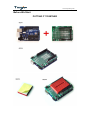
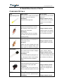
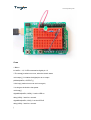
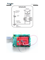
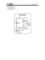
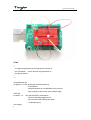
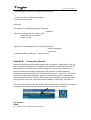
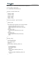
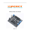
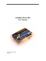
Arduino Start Kit
User Manual
Tinyos Electronics @ 2011
Version 2.0
www.tinyosshop.com
About This KIT
The overall goal of this kit is fun. Beyond this, the aim is to get you comfortable using a
wide range of electronic components through small, simple and easy circuits. The focus is
to get each circuit working then giving you the tools to figure out why. If you encounter any
problems, want to ask a question, or would like to know more about any part, please
contact with us :[email protected].
Kit Details:
Tosduino duemilanove x1
Prototype Shield x1
Breadboard-mini x1
10K ohm Resistor x10
1K ohm Resistor x10
220 ohm Resistor x10
Jumper wire x 20
LED-Red/Green/Yellow x2
Buzzer x1
Pushbutton x4
Segment LED x1
Protoresistor x1
Infrared Receiver x1
LM35 Temperature Sensor x1
Mini Infrared Remote Control x1
Battery Box x1
USB Cable x1
www.tinyosshop.com
Before We Start
PUTTING IT TOGETHER
www.tinyosshop.com
INSTALLING THE IDE
This is the program used to write code for the Arduino. It may seem a little daunting at first
but once you have it installed and start playing around, its secrets will reveal themselves.
Step 1: Download the software
Go to
http://arduino.cc/en/Main/Software download the software for your operating system.
And then there are two ways of Windows and Mac OSX
Windows XP
Step 2: Unzip the Software
Unzip arduino-00xx-win.zip Recommended Path c:\Program Files\
Step 3: Shortcut Icon
Open c:\program files\arduino-00 Right Click Arduino.exe (send to>Desktop (create
shortcut))
Step 4: Plug In Your Arduino
Plug your Arduino in: Using the included USB cable, plug your Arduino board into a free
USB port.Wait for a box to pop up
Step 5: Add new Hardware
Skip searching the internet
(click the next box when prompted to do so)
Install from a specific location
(click “Install from a list or specific location (Advanced)")
Choose the Location
Duemilanove Board:
c:\program files\arduino-00xx\ drivers\FTDI USB Drivers\
Uno Board
c:\program files\arduino-00xx\drivers\
Finished
Vista, Seven
Step 5: Add new Hardware
www.tinyosshop.com
Run Device Manager
Start > Run > devmgmt.msc
Choose the Arduino
Other Devices > Arduino Uno (Uno)
Update Driver
click “Update Driver”
Select Driver
click “Browse My Computer for Driver Software”
c:\program files\arduino-00xx\drivers\
Finished
Mac OSX
Step 2: Open The .dmg
Open (mount) arduino-00xx-mac.dmg (- version).
Step 3: Copy The Application
Go to
"Arduino" (in the devices section of finder)
Move
"Arduino" Application to the
"Applications" folder
Step 4: Install Drivers
Duemilanove Boards Only:.
Go to
"Arduino" device
FTDI Drivers for Intel Macs (x_x_xx).pkg
FTDI Drivers for PPC Macs (x_x_xx).pkg
Restart
Step 5: Plug In Your Arduino
Plug your Arduino in:
Using the included USB cable, plug your Arduino board into a free USB port.
Finished
www.tinyosshop.com
A Small Programming Primer
ARDUINO PROGRAMMING IN BRIEF
The Arduino is programmed in the C language. This is a quick little primer targeted at
people who have a little bit of programing experience and just need a briefing on the
idiosyncracies of C and the Arduino IDE. If you find the concepts a bit daunting, don't
worry, you can start going through the circuits and pick up most of it along the way. For a
more in-depth intro, the Arduino.cc website is a great resource.
STRUCTURE
Each Arduino program (often called a sketch) has two required functions (also called
routines).
void setup(){ }
All the code between the two curly brackets will be run once when your Arduino program first runs.
void loop(){ }
This function is run after setup has finished. After it has run once it will be run again, and again, until
power is removed.
SYNTAX
One of the slightly frustrating elements of C is its formatting requirements (this also makes
it very powerful). If you remember the following you should be alright.
//
(single line comment)
It is often useful to write notes to yourself as you go along about what each line of code does. To do this
type two forward slashes and everything until the end of the line will be ignored by your program.
/* */
(multi line comment)
If you have a lot to say you can span several lines as a comment. Everything between these two symbols
will be ignored in your program.
{}
(curly brackets)
Used to define when a block of code starts and ends (used in functions as well as loops).
;
(semicolon)
Each line of code must be ended with a semicolon (a missing semicolon is often the reason for a program
refusing to compile).
VARIABLES
A program is nothing more than instructions to move numbers around in an intelligent way.
Variables are used to do the moving.
www.tinyosshop.com
int (integer)
The main workhorse, stores a number in 2 bytes (16 bits). Has no decimal places and will store a value
between -32,768 and 32,767.
long (long)
Used when an integer is not large enough. Takes 4 bytes (32 bits) of RAM and has a range between
-2,147,483,648 and 2,147,483,647.
boolean (boolean)
A simple True or False variable. Useful because it only uses one bit of RAM.
float (float)
Used for floating point math (decimals). Takes 4 bytes (32 bits) of RAM and has a range between
-3.4028235E+38 and 3.4028235E+38.
char (character)
Stores one character using the ASCII code (ie 'A' = 65). Uses one byte (8 bits) of RAM. The Arduino
handles strings as an array of char’s.
MATH OPERATORS
Operators used for manipulating numbers. (they work like simple math).
= (assignment)
makes something equal to something else (eg. x= 10 * 2 (x now equals 20))
% (modulo)
gives the remainder when one number is divided by another (ex. 12 % 10 (gives 2))
+ (addition)
- (subtraction)
* (multiplication)
/ (division)
COMPARISON OPERATORS
Operators used for logical comparison.
== (equal to)
(eg. 12 == 10 is FALSE or 12 == 12 is TRUE)
!= (not equal to)
(eg. 12 != 10 is TRUE or 12 != 12 is FALSE)
< (less than)
(eg. 12 < 10 is FALSE or 12 < 12 is FALSE or 12 < 14 is TRUE)
> (greater than)
(eg. 12 > 10 is TRUE or 12 > 12 is FALSE or 12 > 14 is FALSE)
CONTROL STRUCTURE
Programs are reliant on controlling what runs next, here are the basic control elements
(there are many more online).
www.tinyosshop.com
if(condition){ }
else if( condition ){ }
else { }
This will execute the code between the curly brackets if the condition is true, and if not it will test the else
if condition if that is also false the else code will execute.
for(int i = 0; i <#repeats; i++){ }
Used when you would like to repeat a chunk of code a number of times (can count up i++ or down i-- or
use any variable)
DIGITAL
pinMode(pin, mode);
Used to set a pin's mode, pin is the pin number you would like to address 0-19 (analog 0-5 are 14-19). The
mode can either be INPUT or OUTPUT.
digitalWrite(pin, value);
Once a pin is set as an OUTPUT,it can be set either HIGH (pulled to +5 volts) or LOW (pulled to ground).
int digitalRead(pin);
Once a pin is set as an INPUT you can use this to return whether it is HIGH (pulled to +5 volts) or LOW
(pulled to ground).
ANALOG
The Arduino is a digital machine but it has the ability to operate in the analog realm (through tricks).
Here's how to deal with things that aren't digital.
int analogWrite(pin, value);
Some of the Arduino's pins support pulse width modulation (3, 5, 6, 9, 10, 11). This turns the pin on and
off very quickly making it act like an analog output. The value is any number between 0 (0% duty cycle
~0v) and 255 (100% duty cycle ~5 volts).
int analogRead(pin);
When the analog input pins are set to input you can read their voltage. A value between 0 (for 0 volts) and
1024 (for 5 volts) will be returned.
www.tinyosshop.com
A Small Electronics Primer
COMPONENT DETAILS
LED
What it Does:
No. of Leads:
(Light Emitting Diode)
Emits light when a small current is passed
2 (one longer, this one connects
through it. (only in one direction)
to positive)
Identifying:
Things to watch out for:
Looks like a mini light bulb.
- Will only work in one direction
- Requires a current limiting
resistor
Diode
What it Does:
No. of Leads:
The electronic equivalent of a one way
2
valve. Allowing current to flow in one
Things to watch out for:
direction but not the other.
- Will only work in one direction
Identifying:
(current will flow if end with the
Usually a cylinder with wires extending
line is connected to ground)
from either end. (and an off center line
indicating polarity)
Resistors
What it Does:
No. of Leads:
Restricts the amount of current that can 2
2
flow through a circuit.
Things to watch out for:
Identifying:
- Easy to grab the wrong value
Cylinder with wires extending from either
end. The value is displayed using a color
coding system (for details see next page)
Transistor
What it Does:
No. of Leads:
Uses a small current to switch or amplify a
3 (Base, Collector, Emitter)
much larger current.
Things to watch out for:
Identifying:
- Plugging in the right way round
Comes in many different packages but you
(also a current limiting resistor is
can read the part number off the package.
often needed on the base pin)
(8050 in this kit and find a datasheet
online)
Hobby Servo
What it Does:
No. of Leads:
Takes a timed pulse and converts it into an
3
angular position of the output shaft.
Things to watch out for:
Identifying:
- The plug is not polarized so
A plastic box with 3 wires coming out one
make sure it is plugged in the
side and a shaft with a plastic horn out the
right way.
top.
DC Motor
What it Does:
No. of Leads:
Spins when a current is passed through it.
2
Identifying:
Things to watch out for:
www.tinyosshop.com
Buzzer
This one is easy, it looks like a motor.
- Using a transistor or relay that
Usually a cylinder with a shaft coming out
is rated for the size of motor
of one end.
you're using.
What it Does:
No. of Leads:
A pulse of current will cause it to click. A
2
stream of pulses will cause it to emit a
Things to watch out for:
tone.
- Difficult to misuse.
Identifying:
In this kit it comes in a little black barrel,
but sometimes they are just a gold disc.
Pushbutton
Photo Resistor
What it Does:
No. of Leads:
Completes a circuit when it is pressed.
4
Identifying:
Things to watch out for:
A little square with leads out the bottom
- these are almost square so can
and a button on the top.
be inserted 90 degrees off angle.
What it Does:
No. of Leads:
Produces a variable resistance dependant
2
on the amount of incident light.
Things to watch out for:
Identifying:
- Remember it needs to be in a
Usually a little disk with a clear top and a
voltage
curvy line underneath.
divider before it provides a useful
input.
www.tinyosshop.com
Getting Started:
Lesson 1:
Blinking LED
LEDs (light emitting diodes) are used in all sorts of clever things which is why we have
included them in this kit. We will start off with something very simple, turning one on and
off, repeatedly, producing a pleasant blinking effect. To get started, grab the parts listed
below, pin the layout sheet to your breadboard and then plug everything in. Once the
circuit is assembled you'll need to upload the program. To do this plug the Arduino board
into your USB port. Then select the proper port in Tools > Serial Port > (the comm port
of your Arduino). Next upload the program by going to File > Upload to I/O Board
(ctrl+U). Finally, bask in the glory and possibility that controlling lights offers.
THE CIRCUIT:
Parts:
Arduino UNO or MEGA2560 controller x1
Prototyping Shield x1
Mini breadboard x1
5mm Green LED x1
Jumper Wire x2
220 Ohm Resistor x1
www.tinyosshop.com
CODE
/* Blink*/
int ledPin = 13; // LED connected to digital pin 13
// The setup() method runs once, when the sketch starts
void setup() { // initialize the digital pin as an output:
pinMode(ledPin, OUTPUT); }
// the loop() method runs over and over again,
// as long as the Arduino has power
void loop() {
digitalWrite(ledPin, HIGH); // set the LED on
delay(1000); // wait for a second
digitalWrite(ledPin, LOW); // set the LED off
delay(1000); // wait for a second
}
www.tinyosshop.com
Lesson 2:
Buzzer music
Let's tackle sound next. But sound is an analog phenomena, how will our digital Arduino
cope? We will once again rely on its incredible speed which will let it mimic analog behavior.
To do this, we will attach a buzzer to one of the Arduino's digital pins. A buzzer makes a
clicking sound each time it is pulsed with current. If we pulse it at the right frequency (for
example 440 times a second to make the note middle A) these clicks will run together to
produce notes. Let's get to experimenting with it and get your Arduino playing "Twinkle
Twinkle Little Star".
THE CIRCUIT:
Parts:
Arduino UNO or MEGA2560 controller x1
Prototyping Shield x1
Mini breadboard x1
Buzzer x1
Jumper Wire x2
www.tinyosshop.com
CODE
/* Melody
* (cleft) 2005 D. Cuartielles for K3
*
* This example uses a piezo speaker to play melodies. It sends
* a square wave of the appropriate frequency to the piezo, generating
* the corresponding tone.
*
* The calculation of the tones is made following the mathematical
* operation:
*
*
timeHigh = period / 2 = 1 / (2 * toneFrequency)
*
* where the different tones are described as in the table:
*
* note frequency
period
timeHigh
*c
261 Hz
3830
1915
*d
294 Hz
3400
1700
*e
329 Hz
3038
1519
www.tinyosshop.com
*f
*g
*a
*b
*C
*
*/
349 Hz
392 Hz
440 Hz
493 Hz
523 Hz
2864
2550
2272
2028
1912
1432
1275
1136
1014
956
int speakerPin = 9;
int length = 15; // the number of notes
char notes[] = "ccggaagffeeddc "; // a space represents a rest
int beats[] = { 1, 1, 1, 1, 1, 1, 2, 1, 1, 1, 1, 1, 1, 2, 4 };
int tempo = 300;
void playTone(int tone, int duration) {
for (long i = 0; i < duration * 1000L; i += tone * 2) {
digitalWrite(speakerPin, HIGH);
delayMicroseconds(tone);
digitalWrite(speakerPin, LOW);
delayMicroseconds(tone);
}
}
void playNote(char note, int duration) {
char names[] = { 'c', 'd', 'e', 'f', 'g', 'a', 'b', 'C' };
int tones[] = { 1915, 1700, 1519, 1432, 1275, 1136, 1014, 956 };
// play the tone corresponding to the note name
for (int i = 0; i < 8; i++) {
if (names[i] == note) {
playTone(tones[i], duration);
}
}
}
void setup() {
pinMode(speakerPin, OUTPUT);
}
void loop() {
for (int i = 0; i < length; i++) {
if (notes[i] == ' ') {
delay(beats[i] * tempo); // rest
www.tinyosshop.com
} else {
playNote(notes[i], beats[i] * tempo);
}
// pause between notes
delay(tempo / 2);
}
}
Lesson 3:
Segment LED Display
Segement display can be used to display number,this lesson we show how to control
it,here we use the basic 7-segment LED.Common anode.
THE CIRCUIT:
Parts:
Arduino UNO or MEGA2560 controller x1
Prototyping Shield x1
Mini breadboard x1
7 Segment LED x1
Jumper Wire x10
1K Ohm Resistor x8
www.tinyosshop.com
CODE
//设置控制各段的数字IO脚
int a=7;
int b=6;
int c=5;
int d=11;
int e=10;
int f=8;
int g=9;
int dp=4;
//display number 1
void digital_1(void)
{
unsigned char j;
digitalWrite(c,LOW);//Set pin5 to low which lights the C segment
digitalWrite(b,LOW);// Set pin6 to low which lights the C segment
for(j=7;j<=11;j++)//turn off the other segment
digitalWrite(j,HIGH);
www.tinyosshop.com
digitalWrite(dp,HIGH);//turn off dp segment(the little dot on the right down part)
}
//display number 2
void digital_2(void)
{
unsigned char j;
digitalWrite(b,LOW);
digitalWrite(a,LOW);
for(j=9;j<=11;j++)
digitalWrite(j,LOW);
digitalWrite(dp,HIGH);
digitalWrite(c,HIGH);
digitalWrite(f,HIGH);
}
//display number 3
void digital_3(void)
{
unsigned char j;
digitalWrite(g,LOW);
digitalWrite(d,LOW);
for(j=5;j<=7;j++)
digitalWrite(j,LOW);
digitalWrite(dp,HIGH);
digitalWrite(f,HIGH);
digitalWrite(e,HIGH);
}
//display number 4
void digital_4(void)
{
digitalWrite(c,LOW);
digitalWrite(b,LOW);
digitalWrite(f,LOW);
digitalWrite(g,LOW);
digitalWrite(dp,HIGH);
digitalWrite(a,HIGH);
digitalWrite(e,HIGH);
digitalWrite(d,HIGH);
}
//display number 5
void digital_5(void)
{
unsigned char j;
for(j=7;j<=9;j++)
digitalWrite(j,LOW);
www.tinyosshop.com
digitalWrite(c,LOW);
digitalWrite(d,LOW);
digitalWrite(dp,HIGH);
digitalWrite(b,HIGH);
digitalWrite(e,HIGH);
}
//display number 6
void digital_6(void)
{
unsigned char j;
for(j=7;j<=11;j++)
digitalWrite(j,LOW);
digitalWrite(c,LOW);
digitalWrite(dp,HIGH);
digitalWrite(b,HIGH);
}
//display number 7
void digital_7(void)
{
unsigned char j;
for(j=5;j<=7;j++)
digitalWrite(j,LOW);
digitalWrite(dp,HIGH);
for(j=8;j<=11;j++)
digitalWrite(j,HIGH);
}
//display number 8
void digital_8(void)
{
unsigned char j;
for(j=5;j<=11;j++)
digitalWrite(j,LOW);
digitalWrite(dp,HIGH);
}
void setup()
{
int i;
for(i=4;i<=11;i++)
pinMode(i,OUTPUT);//set Pin mode as output
}
void loop()
{
while(1)
{
www.tinyosshop.com
digital_1();//display number 1
delay(2000);//delay 2 senconds
digital_2();
delay(2000);
digital_3();
delay(2000);
digital_4();
delay(2000);
digital_5();
delay(2000);
digital_6();
delay(2000);
digital_7();
delay(2000);
digital_8();
delay(2000);
}
}
Lesson 4:
Pushbuttons
Up to this point we have focused entirely on outputs, time to get our Arduino to listen,
watch and feel. We'll start with a simple pushbutton. Wiring up the pushbutton is simple.
There is one component, the pull up resistor, that might seem out of place. This is included
because an Arduino doesn't sense the same way we do (ie button pressed, button
unpressed). Instead it looks at the voltage on the pin and decides whether it is HIGH or
LOW. The button is set up to pull the Arduino's pin LOW when it is pressed, however, when
the button is unpressed the voltage of the pin will float (causing occasional errors). To get
the Arduino to reliably read the pin as HIGH when the button is unpressed, we add the pull
up resistor.
THE CIRCUIT:
Parts:
Arduino UNO or MEGA2560 controller x1
Prototyping Shield x1
Mini breadboard x1
Pushbutton x1
Jumper Wire x4
10K Ohm Resistor x1
220 Ohm Resistor x1
Red LED x1
www.tinyosshop.com
www.tinyosshop.com
CODE
int ledPin = 13; // choose the pin for the LED
int inputPin = 2; // choose the input pin (for a pushbutton)
int val = 0; // variable for reading the pin status
void setup() {
pinMode(ledPin, OUTPUT); // declare LED as output
pinMode(inputPin, INPUT); // declare pushbutton as input
}
void loop(){
val = digitalRead(inputPin); // read input value
if (val == HIGH) { // check if the input is HIGH
digitalWrite(ledPin, LOW); // turn LED OFF
} else {
digitalWrite(ledPin, HIGH); // turn LED ON
}
}
Lesson 5:
Light Sensor
Whilst getting input from a potentiometer can be useful for human controlled experiments,
what do we use when we want an environmentally controlled experiment? We use exactly
the same principles but instead of a potentiometer (twist based resistance) we use a photo
resistor (light based resistance). The Arduino cannot directly sense resistance (it senses
voltage) so we set up a voltage divider . The exact voltage at the sensing pin is calculable,
but for our purposes (just sensing relative light) we can experiment with the values and
see what works for us. A low value will occur when the sensor is well lit while a high value
will occur when it is in darkness.
THE CIRCUIT:
Parts:
Arduino UNO or MEGA2560 controller x1
Prototyping Shield x1
Mini breadboard x1
www.tinyosshop.com
Proto-Resistor x1
Jumper Wire x4
10K Ohm Resistor x2
220 Ohm Resistor x1
Green LED x1
www.tinyosshop.com
CODE
/*
* A simple programme that will change the intensity of
* an LED based * on the amount of light incident on
* the photo resistor.
*
*/
//PhotoResistor Pin
int lightPin = 0; //the analog pin the photoresistor is
//connected to
//the photoresistor is not calibrated to any units so
//this is simply a raw sensor value (relative light)
//LED Pin
int ledPin = 9; //the pin the LED is connected to
//we are controlling brightness so
//we use one of the PWM (pulse width
// modulation pins)
void setup()
{
www.tinyosshop.com
pinMode(ledPin, OUTPUT); //sets the led pin to output
}
/*
* loop() - this function will start after setup
* finishes and then repeat
*/
void loop()
{
int lightLevel = analogRead(lightPin); //Read the
// lightlevel
lightLevel = map(lightLevel, 0, 900, 0, 255);
//adjust the value 0 to 900 to
//span 0 to 255
lightLevel = constrain(lightLevel, 0, 255);//make sure the
//value is betwween
//0 and 255
analogWrite(ledPin, lightLevel); //write the value
}
Lesson 6:
Temperature Sensor
What's the next phenomena we will measure with our Arduino? Temperature. To do this
we'll use a rather complicated IC (integrated circuit) hidden in a package identical to our
8050 transistors. It has three pin's, ground, signal and +5 volts, and is easy to use. It
outputs 10 millivolts per degree centigrade on the signal pin (to allow measuring
temperatures below freezing there is a 500 mV offset eg. 25 C = 750 mV, 0 ). To convert
this from the digital value to degrees, we will use some of the Arduino's math abilities.
Then to display it we'll use one of the IDE's rather powerful features, the debug window.
We'll output the value over a serial connection to display on the screen. Let's get to it.
One extra note, this circuit uses the Arduino IDE's serial monitor. To open this, first upload
the program then click the button which looks like a square with an antennae.
THE CIRCUIT:
Parts:
Arduino UNO or MEGA2560 controller x1
www.tinyosshop.com
Prototyping Shield x1
Mini breadboard x1
LM35 Temperature Sensor x1
Jumper Wire x3
www.tinyosshop.com
CODE
int temperaturePin = 0;
int tempc =0;
int samples[8];
int maxi=-100,mini=100;
int i;
/*
* setup() - this function runs once when you turn your Arduino on
* We initialize the serial connection with the computer
*/
void setup()
{
Serial.begin(9600); //Start the serial connection with the copmuter
//to view the result open the serial monitor
//last button beneath the file bar (looks like a box with an
antenae)
}
www.tinyosshop.com
void loop()
// run over and over again
{
for(i=0;i<=7;i++)
{
samples[i]=(5.0*analogRead(temperaturePin)*100.0)/1024.0;
tempc =tempc + samples[i];
delay(100);
}
tempc =tempc/8.0;
if(tempc>maxi){maxi =tempc;}
if(tempc<mini){mini =tempc;}
Serial.print(tempc,DEC);
Serial.print(" Celsius ");
Serial.print(maxi,DEC);
Serial.print(" Max, ");
Serial.print(mini,DEC);
Serial.println(" Min ");
tempc =0;
delay(100);
}
Lesson 7:
IR Romote Control
Wireless control? Cool! In this lesson we use a Infrared reveiver and a remote control to
turn on a LED or a Buzzer. LED on when you press the VOL+ button and buzzer beep
when you press the VOL- button. How to do that? Please follow me.
THE CIRCUIT:
Parts:
Arduino UNO or MEGA2560 controller x1
Prototyping Shield x1
Mini breadboard x1
IR Receiver x1
Jumper wire x7
220 Ohm Resistor x1
Buzzer x1
Yellow LED x1
www.tinyosshop.com
CODE
#define BUZZER 10//connect buzzer to digital pin 10
#define LED_RED 11//connect LED to digital pin 11
www.tinyosshop.com
#define IR_IN 8 //connect the Infrared receiver to digital pin 8
int Pulse_Width=0; //pulse width
int ir_code=0x00; //IR command code
void timer1_init(void) //initilize timer
{
TCCR1A = 0X00;
TCCR1B = 0X05;
TCCR1C = 0X00;
TCNT1 = 0X00;
TIMSK1 = 0X00;
}
void remote_deal(void) //get IR command
{
switch(ir_code)
{
case 0xff00://press stop button on the remote controller
digitalWrite(LED_RED,LOW);//turn off LED
digitalWrite(BUZZER,LOW);//silence the buzzer
break;
case 0xfe01://VOL+
digitalWrite(LED_RED,HIGH);//turn on led
break;
case 0xf609://VOLdigitalWrite(BUZZER,HIGH);//buzzer beep
break;
}
}
char logic_value()
{
while(!(digitalRead(8)));
Pulse_Width=TCNT1;
TCNT1=0;
if(Pulse_Width>=7&&Pulse_Width<=10)
{
while(digitalRead(8));
Pulse_Width=TCNT1;
TCNT1=0;
if(Pulse_Width>=7&&Pulse_Width<=10)
return 0;
else if(Pulse_Width>=25&&Pulse_Width<=27)
return 1;
}
www.tinyosshop.com
return -1;
}
void pulse_deal()
{
int i;
for(i=0; i<8; i++)
{
if(logic_value() != 0)
return;
}
for(i=0; i<6; i++)
{
if(logic_value()!= 1)
return;
}
if(logic_value()!= 0)
return;
if(logic_value()!= 1)
return;
ir_code=0x00;
for(i=0; i<16;i++ )
{
if(logic_value() == 1)
{
ir_code |=(1<<i);
}
}
}
void remote_decode(void)
{
TCNT1=0X00;
while(digitalRead(8))
{
if(TCNT1>=1563)
{
ir_code = 0xff00;
return;
}
}
www.tinyosshop.com
TCNT1=0X00;
while(!(digitalRead(8)));
Pulse_Width=TCNT1;
TCNT1=0;
if(Pulse_Width>=140&&Pulse_Width<=141)//9ms
{
while(digitalRead(8));
Pulse_Width=TCNT1;
TCNT1=0;
if(Pulse_Width>=68&&Pulse_Width<=72)
{
pulse_deal();
return;
}
else if(Pulse_Width>=34&&Pulse_Width<=36)//2.25ms
{
while(!(digitalRead(8)));
Pulse_Width=TCNT1;
TCNT1=0;
if(Pulse_Width>=7&&Pulse_Width<=10)//560us
{
return;
}
}
}
}
void setup()
{
unsigned char i;
pinMode(LED_RED,OUTPUT);
pinMode(BUZZER,OUTPUT);
pinMode(IR_IN,INPUT);
}
void loop()
{
timer1_init();
while(1)
{
remote_decode();
remote_deal();
}
}