1
ECED 3204 – Microprocessors – Lab #4. Timers ECED3204 – Lab #4 STUDENT NAME(s): . STUDENT NUMBER(s): B00 . PreLab Information It is recommended that you read this entire lab ahead of time. Doing so will save you considerable time during the lab, as you will be required to write some simple C code during this lab! Overall Objective This lab has several main objectives:
Learn about using timers for event timing Learn about Pulse Width Modulation (PWM) Learn about Input Capture mode to measure pulse width NOTE: This lab has a video overview at http://www.youtube.com/watch?v=OEyqhfrqMgo&hd=1 1 ECED 3204 – Microprocessors – Lab #4. Timers Part #1: Timing Events Objective
Familiarize yourself with using a timer and interrupt. Required Materials
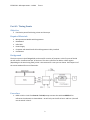
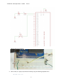
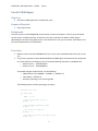
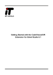
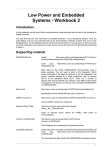
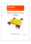
Microprocessor Module with Programmer Breadboard USB Cable Power Supply Computer with Atmel Studio 6.2 and Programmer Utility installed Push Button Background The timer system in the ATMega644P can be used for a variety of purposes. In this first part of the lab we will use the ‘overflow interrupt’ of the timer. The timer system has an 8‐bit or 16‐bit register (depending on the timer being used), which is incremented on a rate you can choose. See Chapter 11 of the course textbook for more information. Procedure 1. Build a similar circuit from Part #1 of Lab #3, except connect the switch to PORTD.6. For reference the schematic is shown below – we will only use the LED in Part 1 and Part 2, but will use the switch in Part 3. 2 ECED 3204 – Microprocessors – Lab #4. Timers Which might look as follows: 2. Start a new C/C++ project (see Lab #1 for details), copy the following template into it: #include <avr/io.h>
3 ECED 3204 – Microprocessors – Lab #4. Timers #include <avr/interrupt.h>
volatile unsigned int tick;
#define LED_ON() PORTD |= 1<<7
#define LED_OFF() PORTD &= ~(1<<7)
int main(void)
{
DDRD |= 1<<7;
//Timer configuration
TCCR0A = ?
TCCR0B = ?
//Interrupt mask enables
TIMSK0 = ?
//Enable global interrupts
sei();
while(1);
}
ISR(SPECIFY_NAME_HERE)
{
//Code here
;
}
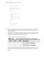
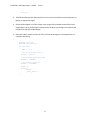
3. Before being able to compile this code, we need to finish a few things. The first is to determine the setup of TCCR0A and TCCR0B. We want the timer to overflow somewhere between 100‐
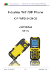
5000 times per second. The clock source for the AVR is a 14745600Hz crystal (we learned this in Lab #1). If you used this to directly drive an 8‐bit counter, the counter would overflow at the rate of 14745600 ÷ 28 = 14745600 ÷ 256 = 57600 times per second. That is too fast! Finding Table 13‐9, you can see some prescaler settings: Using a prescaler of 64 would mean the timer now overflows 900 times per second. This tells us the setting for two bits in the TCCR0B register, as these CS00/CS01/CS02 bits are present in this register: 4 ECED 3204 – Microprocessors – Lab #4. Timers We will use the default (all‐0) settings for TCCR0A: See the datasheet for a description of those bits. This means our setup area of the code looks like this: //Timer configuration
TCCR0A = 0;
TCCR0B = (1 << CS00) | (1 << CS01);
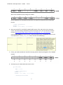
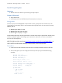
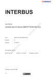
4. Next you need to fill in the SPECIFY_NAME_HERE section of the code, which is the interrupt vector. This routine will get called every time the interrupt occurs. You can find a list of all the names at http://www.nongnu.org/avr‐libc/user‐manual/group__avr__interrupts.html ‐ you must be VERY CAREFUL to ensure you use a name that exists on the ATmega644P device! In this case look for the TIMER0_OVF_vect name, as shown in the following: 5. Finally, you need to enable the ‘overflow’ interrupt, which is done by setting bit 1 of the TIMSK0 register: 6. At this point, your code should look similar to this: int main(void)
{
DDRD |= 1<<7;
//Timer configuration
TCCR0A = 0;
TCCR0B = (1 << CS00) | (1 << CS01);
//Interrupt mask enables
5 ECED 3204 – Microprocessors – Lab #4. Timers TIMSK0 |= 1 << TOIE0;
//Enable global interrupts
sei();
while(1);
}
ISR(TIMER0_OVF_vect)
{
//Code here
;
}
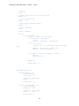
7. Finally, program the interrupt service routine (ISR) to toggle the LED. An example implementation is as follows, using the ‘tick’ variable to keep track of how many runs through the interrupt routine have occurred: ISR(TIMER0_OVF_vect)
{
tick++;
if(tick == 1){
LED_ON();
} else if (tick == 400){
LED_OFF();
} else if (tick > 900){
tick = 0;
}
}
8. Adjust the delay to blink 5 seconds on, 5 seconds off. 6 ECED 3204 – Microprocessors – Lab #4. Timers Part #2: PWM Output Objective
Generate a PWM signal with a variable duty cycle. Required Materials
Setup from Part #1 Background The timer system in the ATMega644P can be used for a variety of purposes. In this first part of the lab we will use the ‘overflow interrupt’ of the timer. The timer system has an 8‐bit or 16‐bit register (depending on the timer being used), which is incremented on a rate you can choose. See Chapter 11 of the course textbook for more information. Procedure 1. Build the same circuit from Part #1 of this lab, or if you just completed Part #1 leave your circuit as‐is. 2. Using Timer 2, generate a Pulse Width Modulation (PWM) signal of around 2‐10 kHz. Output this on in PD7 (which is the OC2A pin). You will need the following references in the datasheet: o Section 15.11.1 – TCCR2A Register o Section 15.11.2 – TCCR2B Register You should configure timer/counter 2 as the following: o PWM, Phase Correct (WGM2 = 0, WGM1 = 1, WGM0 = 0) o Clock divider = IOClock / 8 o OC2A pin operating in non‐inverting mode The following shows the basic operating instructions: #include <avr/io.h>
int main(void)
{
DDRD |= 1<<7;
//Set clock divider to be /8
TCCR2B = ??
//Set waveform generation mode
TCCR2A |= ??
//Set output on OC2A pin
TCCR2A |= ??
//Set PWM to half-way (50% duty cycle)
OCR2A = 127;
7 ECED 3204 – Microprocessors – Lab #4. Timers while(1);
}
3. The LED should be partially illuminated now. You can also check with an oscilloscope you are getting an appropriate signal. 4. Set the OCR2A register to various values in the range 0‐255, and observe the effect on the output signal. Use an oscilloscope to measure how the duty cycle changes, and measure the frequency as well of the PWM output. 5. Add some code to slowly increase the value, and see what happens. For example here is a complete code listing: #include <avr/io.h>
#include <util/delay.h>
int main(void)
{
DDRD |= 1<<7;
//Set clock divider to be /8
TCCR2B = 1<<CS21;
//Set waveform generation mode
TCCR2A |= 1<<WGM20;
//Set output on OC2A pin
TCCR2A |= 1<<COM2A1;
OCR2A = 0;
while(1){
OCR2A++;
_delay_ms(50);
}
}
8 ECED 3204 – Microprocessors – Lab #4. Timers Part #3: Input Capture Objective
Measure the time a button is pressed using the input capture Required Materials
Setup from Part #1 Push‐Button wired into PORTD.6 (should have been done in Part #1) Background The timer system in the ATMega644P can be used for a variety of purposes. This section will use the ‘Input Capture’ functionality, which is used to measure the length of a pulse. You can use this for many features, such as: 1) Measuring the width of a pulse 2) Measuring the duty cycle of a signal 3) Measuring the frequency of a signal We will measure the length of time a push‐button is pressed. If the button is pressed for a length of time inside our ‘allowed’ range, an LED will light up. If you press the button for too short or too long of a time, the LED will not light up. NOTE: This lab has a video overview at http://www.youtube.com/watch?v=OEyqhfrqMgo&hd=1 . It may be useful to see the system operating to understand the push button operation. Procedure 1. Ensure you have the same setup as previous parts, including the button connect to PORTD.6 2. Start a new project (or re‐use the project from the previous parts), and load the following template: #include
#include
#include
#include
<avr/io.h>
<avr/interrupt.h>
<stdint.h>
<util/delay.h>
#define LED_ON() PORTD |= 1<<7
#define LED_OFF() PORTD &= ~(1<<7)
volatile unsigned char current_edge = 0;
volatile uint16_t
starting_cnt;
volatile uint16_t
ending_cnt;
int main(void)
{
//LED as output
DDRD = 1<<7;
//Pull-up on ICP
PORTD |= 1<<6;
9 ECED 3204 – Microprocessors – Lab #4. Timers //Defaults
TCCR1A = 0;
//Enable noise cancel, look for falling edge
TCCR1B = ???
//Clock divided by 1024
TCCR1B |= ???
//Input capture interrupt Enable
TIMSK1 |= ???
//Enable interrupts
sei();
uint16_t timediff;
while(1){
if(current_edge == 2){
//Check for normal (no wrap-around)
if (starting_cnt < ending_cnt){
//A - B
timediff = ending_cnt - starting_cnt;
} else {
//wrap around
//(0xffff + A) - B, done without requiring signed
math
timediff = starting_cnt - ending_cnt;
timediff = 0xffff - timediff;
}
if ((timediff > 10000) && (timediff < 30000)){
LED_ON();
_delay_ms(5000);
}
LED_OFF();
current_edge = 0;
}
}
}
ISR(TIMER1_CAPT_vect)
{
if(current_edge == 0){
//Save timestamp
starting_cnt = ???;
//Switch to rising edge
TCCR1B |= ????
current_edge = 1;
} else if (current_edge == 1){
//Save timestamp
ending_cnt = ICR1;
//Switch to falling edge
TCCR1B &= ~(????);
current_edge = 2;
10 ECED 3204 – Microprocessors – Lab #4. Timers }
TIFR1 |= (1<<ICF1);
}
3. Using the register settings for TIMER1 from the ATMega644A datasheet, fill in the blanks above. The objective of this code is to measure the length of time the push‐button signal is low, as when the button is pressed the input capture line goes low. 11 ECED 3204 – Microprocessors – Lab #4. Timers Lab Questions 1.
2.
3.
4.
In Part 1, we uses an interrupt which is called periodically. What is the fastest number of times we could call that interrupt using the timer overflow interrupt (i.e. using the lowest possible clock prescaller, giving you the fastest clock operation)? Would you foresee any issues calling the interrupt that quickly? What was the frequency of the PWM signal? How would you use the input capture feature to measure the distance to an object if you have a “Time of Flight” sensor, which generates a pulse indicating how long it took a sound echo to reflect off an object? In Part 3, the button must be pressed for between 10 000 and 30 000 counts of the input capture register. Based on the Timer1 prescaler settings and the system operating frequency, what duration does that correspond to? 12