1
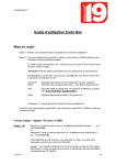
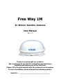
Free Way 1M
In Motion Satellite Antenna
User Manual
Ver. 1.0
Thanks to have bought our products.
We recommend to read all this instructions manual before
installing and making use of the l'antenna.
Please, fill in the gap beneath with the antenna's serial number.
In case of problems, please transmit the following number:
Serial Nr. : _________________________________
Free Way 1M
T
1
User Manual Ver. 1.0
able of contents
Introduction
1.1 Specifications..............................................................................................6
1.2 Antenna systems overview............................................................................7
1.3 Direct broadcast satellite overview................................................................. 8
1.4 System components.....................................................................................9
2
Installation
2.1 Unpacking the unit..................................................................................... 11
2.2 Preparing for the installation ....................................................................... 12
2.3 Selecting the location................................................................................. 13
2.4 Equipment and cable installaion .................................................................. 14
2.5 Setting the LNB Skew................................................................................. 15
3
Operation
3.1 Receiving satellite TV signals....................................................................... 18
3.2 Turning the systems On / Off ...................................................................... 18
3.3 Changing channels..................................................................................... 19
3.4 Watching TV ............................................................................................. 19
3.5 Switching between satellites ....................................................................... 19
3.6 Operating the Control Box .......................................................................... 20
4
Troubleshooting
4.1 Simple check............................................................................................. 25
4.2 Causes and remedies ................................................................................. 26
-2-
http://www.continental-corporation.com
Free Way 1M
i
User Manual Ver. 1.0
Appendix A
How to set the Skew angle............................................................................... 28
ii
Appendix B
Satellite coverage map..................................................................................... 33
iii
Appendix C
Firmware Upgrade........................................................................................... 37
iii
Appendix D
Antenna drawing............................................................................................. 40
-3-
http://www.continental-corporation.com
Free Way 1M
User Manual Ver. 1.0
Figures
Figure 1-1
System diagram ..............................................................7
Figure 1-2
Satellite blockage ............................................................8
Figure 1-3
Systems components .......................................................9
Figure 2-1
Unpacking the unit ........................................................ 11
Figure 2-2
Selecting the location..................................................... 13
Figure 2-3
Satellite signals ............................................................. 15
Figure 2-4
Best Skew angle............................................................ 15
Figure 3-1
Control Boc LCD screen.................................................. 19
Figure 3-2
Appearance of Control Box ............................................. 20
Figure 3-3
Functions of LCD display ................................................ 20
Figure A-1
Europe position grid....................................................... 29
Figure A-2
The back of the reflector ................................................ 31
Figure A-3
LNB Skew angle adjustment ........................................... 32
Figure B-1
Astra 2N coverage map.................................................. 34
Figure B-2
Astra 2S coverage map .................................................. 34
Figure B-3
Astra 1 coverage map .................................................... 35
Figure B-4
Hotbird coverage map.................................................... 35
Figure B-5
Sirius coverage map ...................................................... 35
Figure B-6
Thor coverage map ....................................................... 35
Figure B-7
Atlantic Bird 4 coverage map .......................................... 36
Figure B-8
Hipasat coverage map ................................................... 36
Figure C-1
SD Memory Card ........................................................... 38
Figure C-2
Formatting SD Memory Card........................................... 38
Figure C-3
The back of Control Box................................................. 39
Figure C-1
Antenna drawing........................................................... 40
Tables
Table 1-1
Specifications ................................................................... 6
Table 2-1
Parts included................................................................. 11
Table A-1
Regional Skew angle ....................................................... 30
-4-
http://www.continental-corporation.com
Free Way 1M
User Manual Ver. 1.0
Notes, Cautions, and Warnnings
Caution – Improper handling by unqualified personnel can
cause serious damage to this equipment. Unqualified
personnel who tamper with this equipment may be held liable
for any resultant damage to the equipment.
Install under DRY condition ONLY! Do not install this system in
the rain, or under any wet conditions. Moisture may affect
electronics and void warrenty!
Warning – Need 2 people to install the antenna onto the roof.
Do not try to install the antenna by yourself.
Note – Before you begin, carefully read each of the
procedures in this manual. If you have not performed similar
operations on comparable equipment, do not attempt to
perform these procedures.
-5-
http://www.continental-corporation.com
Free Way 1M
I
User Manual Ver. 1.0
ntroduction
The Free Way 1M satellite antenna system is the innovative and a technologically
advanced satellite In-Motion system. The Free Way 1M has a unique combination of
state-of-the art components with the most sophisticated satellite acquisition and tracking
programs to provide the following features:
• Fast satellite acquisition
• Compatible with any Satellite Receiver
• Compatible with all Direct Broadcast Satellites (DBS)
• Built-in Digital Broadcast Receiver(DVB)
• Capable of High Definition receiving
1.1 Specifications
Antenna Type
Parabola
Frequency Band
Banda Ku
Frequency Range
11,7 GHz – 12,75 GHz
Dish Dimension
390 x 700 mm
Antenna Weight
9 Kg
Antenna Gain
33 dBi
Minimum EIRP
49 dBW
Polarization
V/H o RHCP/LHCP
Type of Stabilization
2-axis Step Motor
Elevation Range
19° - 64°
Azimuth Range
Unlimited
Tracking Rate
50° /sec
Temperate Range
da -20° a 70°
Power
12-24 V DC
Table 1-1
Specifications
-6-
http://www.continental-corporation.com
Free Way 1M
User Manual Ver. 1.0
1.2 Antenna system overview
A complete satellite TV system, illustrated in Figure 1-1, includes the Free Way 1M
antenna connected to a IDU, a satellite TV receiver, and a television set.
ITA-082-000-004
Antenna
12~24 V DC
Satellite Receiver
Control Box
(IDU)
Monitor
TV
Figure 1-1
System diagram
-7-
http://www.continental-corporation.com
Free Way 1M
User Manual Ver. 1.0
1.3 Direct broadcast satellite overview
Direct Broadcast Service (DBS) satellites broadcast audio, video and data information
from satellites located 22,000 miles in space. A receiving station, such as the Free Way
1M antenna, should include a dish and satellite receiver to receive the signals and
process them for use by the consumer audio and video equipment. The system
requires a clear view of the satellite to maximize the signal reception.
Segnale bloccato !
Figure 1-2
Satellite blockage
Objects such as tall houses, bridges and big trees that block this view will cause a loss
of signal. The signal will be quickly restored once the antenna has a clear line of sight
again. Heavy rain, cloud, snow or ice may also interfere with the signal reception quality.
If the satellite signal is lost due to blockage or severe weather condition, services from
the receiver will be lost (picture will freeze frame and may disappear). When the
satellite signal strength is again high enough, then the receiver will resume providing
desired programming services.
-8-
http://www.continental-corporation.com
Free Way 1M
User Manual Ver. 1.0
1.4 System components
Antenna
The antenna unit houses the antenna
positioning mechanism, LNB (low noise
block), and control elements within a
radome. Weathertight connectors join the
power, signal, and control cabling from the
belowdecks units.
Control Box
The Control Box (IDU – Indoor Unit) is the
system’s user interface, providing access to
the system and its functions. The Control
Box also serves as the vehichle’s junction
box, allowing the system to use vehicle
power, and supply and receive data to/from
the antenna unit.
Figure 1-3
System components
-9-
http://www.continental-corporation.com
Free Way 1M
I
User Manual Ver. 1.0
nstallation
This section offers a general explanation of how properly to install the Free Way 1M
antenna. Installation of the Free Way 1M antenna must be accomplished by or under
the supervision of an authorized dealer for the Limited Warranty to be valid and in force.
The steps in the installation and setup process are as follows:
Unpacking the unit..................................................................................11
Preparing for the installation....................................................................12
Selecting the location ..............................................................................13
Equipment and cablae installation ............................................................15
Setting the LNB Skew angle.....................................................................14
- 10 -
http://www.continental-corporation.com
Free Way 1M
User Manual Ver. 1.0
2.1 Unpacking the unit
1. Open the box and removing the packing material
The following items are included in the packaging of the Free Way 1M antenna.
Item
Description
Quantity
1
Free Way 1M Antenna Unit
1 pc
2
IDU(In Door Unit)
1 pc
3
Power Cable
1 pc
4
Coaxial Cable (10 cm)
1 pc
5
Coaxial Cable (1 m)
1 pc
6
User Manual
1 set
Table
2-1 Parts included
2. Lift dome out of box vertically. Do not turn box and “roll” out, or turn
upside down to remove.
Figure 2-1 Unpacking the unit
- 11 -
http://www.continental-corporation.com
Free Way 1M
User Manual Ver. 1.0
2.2 Preparing for the installation
1. Install Tools and Materials
The Free Way 1M antenna system is designed for simple installation and setup. However,
the following list of equipment or items should be available during installation of the Free
Way 1M antenna.
§ Electric drill and drill bits
§ Socket wrench
§ Silicon sealant
§ Fastener suitable for specific application
2. Verification of the vehicle's power supply
§ Confirm that the vehicle’s power supply is 12VDC~24VDC.
3. Verification of the satellite receiver and Control Box's attachment and the
electricity supply
§ Attach satellite receiver and Control Box in the interior of the vehicle of the
trunk
§ Connect the power of satellite receiver and Control Box
§ Once the power of Satellite Receiver and Control Box is verified, it confirms
that both Satellite Receiver and Control Box are working normally.
4. Procedure of the satellite's attachment and installation
§ Attach the satellite on the flat surface area of the vehicle’s roof.
§ Connect each end of the Coaxial antenna cable to the satellite’s terminal and
the Control Box.
§ Connect the Control Box and the Satellite Receiver box together through the
coaxial cable.
§ Make sure that the satellite is working normally, once the power is supplied.
Warning: things to consider when installing the antenna:
§
Turn off the power when attaching or detaching the antenna.
§
Make sure that the attached satellite is fixed on the flat
surface.
§
Ensure that all the cables are connected properly.
- 12 -
http://www.continental-corporation.com
Free Way 1M
User Manual Ver. 1.0
2.3 Selecting the location
Determine the optimum mounting location for the antenna radome assembly. It should be
installed where :
1. The antenna has a clear line-of-sight view to as much of the sky as is practical.
Choose a location where masts or other structures do not block the satellite signal
from the dish as the vehichle turns.
2. The antenna is at least 5 feet away from other transmitting antennas (HF, VHF and
radar) that may generate signals that may interfere with the Free Way 1M antenna.
The further away the Free Way 1M antenna is from these other antennas, the less
impact their operation will have on it.
3. Direct radiation into the antenna from vehicle radar, especially high power surveillance
radar arrays, is minimized. The radome should be as far away from the vehicle Radar
as possible and should NOT be mounted on the same plane as the vehicle Radar.
4. The antenna radome assembly should be rigidly mounted to the vehichle. If necessary,
reinforce the mounting area to assure that it does not flex due to the vehichle motion
or vibration.
If these conditions cannot be entirely satisfied, the site selection will inevitably be a
“best” compromise between the various considerations.
Best
position
Poor position
Figure 2-2 Selecting the location
- 13 -
http://www.continental-corporation.com
Free Way 1M
User Manual Ver. 1.0
2.4 Equipment and cable installation
This offers a general explanation of how to install the Control Box and satellite receiver
properly to the inside of vehichle connecting with coaxial cable.
1. The coaxial cable is routed from the antenna to the Control Box inside the vehicle.
2. After once deciding where to place the Control Box and satellite receiver, make sure
that both units are placed in a dry and protected area.
3. The Control Box and satellite receiver should be placed away from any heat source
and in an area with proper ventilation.
4. Ensure that there are at least 3cm of space around both units for ventilation and
connection of cables. Do not stack the units on top of each other.
5. Connect the coaxial cable to the Free Way 1M antenna port on the back of the Control
Box
6. Connect the secondo coaxial cable between the Control Box and the satellite receiver
- 14 -
http://www.continental-corporation.com
Free Way 1M
User Manual Ver. 1.0
2.5 Setting the LNB skew angle automatically
(only models with Auto-Skew function)
Figure 2-3 Satellite signals
Signals transmitted in vertical(red) and horizontal(blue) wave offset exactly 90º from
each other. Since linear satellite signals are oriented in a precise cross pattern, the Free
Way 1M antenna’s receiving element, called an LNB (low-noise block) must be oriented in
the same way to optimize reception. This orientation adjustment is referred to as the
LNB’s “skew angle.” Figure 2-4 illustrates how skew determines the amount of signal the
LNB collects. The more signal, the better reception.
: Convertitore LNB
: Satellite Signal
Bad Skew
Good Skew
Best Skew
Figure 2-4 Best Skew Angle
- 15 -
http://www.continental-corporation.com
Free Way 1M
User Manual Ver. 1.0
The correct skew setting varies depend on your geographic location, since the
orientation of your antenna to the satellite changes as you move. Free Way 1M is
automatically set by GPS and skew motor. GPS gives skew controller location
information. Then, skew controller command to skew motor. The skew motor changes
the LNB angle and hold on the LNB. If you move to other area, the skew angle may be
changed.
- 16 -
http://www.continental-corporation.com
Free Way 1M
User Manual Ver. 1.0
O
peration
The Free Way 1M antenna system is easy to use. Under normal conditions, operation
of the Free Way 1M antenna requires no intervention from the user. Antenna unit
initialization and satellite acquisition is completely automatic.
Receiving satellite TV signal.................................................................. 18
Turning the System On/Off ................................................................... 18
Changing Channels .............................................................................. 19
Watching TV ........................................................................................ 19
Switching between Satellites................................................................. 19
Operating the Control Box .................................................................... 20
- 17 -
http://www.continental-corporation.com
Free Way 1M
User Manual Ver. 1.0
3.1 Receiving Satellite TV signals
Television satellites are located in fixed positions above the Earth’s equator and beam TV
signals down to certain regions of the planet. To receive TV signals from a satellite, you
must be located within that satellite’s unique coverage area. To check it, see “Appendix B
– Satellite Coverage Map” In addition, since TV satellites are located above the equator,
the Free Way 1M antenna must have a clear view of the sky to receive satellite TV signals.
Anything that stands between the antenna and the satellite can block the signal, resulting
in lost reception. Common causes of blockage include tall houses, bridges, builidings and
big trees. Heavy rain, ice, or snow might also temporarily interrupt satellite signals.
3.2 Turning the system On/Off
Since power to the Free Way 1M system is controlled by the Control Box, you can turn
the antenna on or off by applying/removing operating power to the Control Box.
Turning on the system
Follow the steps below to turn on your Free Way 1M System.
1. Make sure the antenna has a clear view of the sky.
2. Turn on your satellite TV receiver and TV.
3. Apply operating power to the Control Box.
4. Wait one minute for system startup. The Control Box will display the
Tracking Satellite screen after system testing is complete.
Turning off the System
Follow the steps below to turn off your Free Way 1M System.
1. Remove operating power from the Control Box.
2. Turn off your satellite TV receiver and TV.
- 18 -
http://www.continental-corporation.com
Free Way 1M
User Manual Ver. 1.0
3.3 Changing channels
If you have followed the installation instructions, your system should be set to the
satellite of your choice and the system should have downloaded the appropriate channel
guides. When the Free Way 1M antenna system and satellite receiver is properly
configured, it is easy to change the channel using the remote control that normally
comes with the receiver unit.
3.4 Watching TV
The Free Way 1M antenna is designed to operate as efficiently and as reliably as
possible when the vehichle is moved and anchored. It is also the quickest satellite
acquisition system available among the Free Way 1M antennas. If you have anchored
the vehichle and the antenna has completed to searching selected satellite, turn off
Control Box Power to avoid unnecessary use of power. Because the LNB receives its
power from the Satellite Receiver through the Control Box, the antenna will continue to
receive the satellite TV signals.
3.5 Switching between Satellites
You can switch between satellites using the IDU by pressing Satellite select buttons.
Follow the steps below to switch to another satellite.
1. Ensure that the Control Box's leds are on.
HOTBIRD
ID: HOT
AUTO_SLP S : 280
Figure 3-1
Control Box Leds
2. Press the Satellite select buttons to switch to another satellite.
3. The antenna shifts to track selected satellite. Wait for the ending of
Tracking Satellite operation.
- 19 -
http://www.continental-corporation.com
Free Way 1M
User Manual Ver. 1.0
3.6 Operating the Control Box
Appearance
Power S/W
ON
OFF
POWER
Display LCD
SATELLITE
SELECT
VDO
SLEEP
Satellite select button
Figure 3-2
Sleep button
Appearance of Control Box
Functions of LCD Display
ON
OFF
POWER
SATELLITE
SELECT
VDO
SLEEP
Zoom in
User selected
Satellite ID
satellite
Current operational
Intensità of received
status
signal
Figure 3-3
Functions of LCD Display
- 20 -
http://www.continental-corporation.com
Free Way 1M
User Manual Ver. 1.0
Explanation of words in LCD
-
INIT : It shows condition of initializing the antenna.
INIT-SCH : It shows condition of initial search mode.
SAT-MOVE: It shows condition of moving to another satellite.
S:xxx : It shows intensity of signal.
ID:xxx : It shows ID of acquired satellite.
GYRO-CAL : It shows condition of calibrating the Gyro Sensor.
SEARCH : It shows condition of searching.
TRACKING : It shows condition of tracking the satellite.
RE_SEARCH : It shows condition of researching the satellite.
AUTO_SLP : It show condition of auto-sleep mode
General Operation Order
ON
Turn the power switch on
OFF
POWER
Information of IDU
SATELLITE
SELECT
LCD shows information of Control Box
Push the satellite select button to choose
satellite
- 21 -
http://www.continental-corporation.com
Free Way 1M
HOTBIRD
User Manual Ver. 1.0
It notices the start
START !!!
HOTBIRD
The antenna is being initialized
INIT
HOTBIRD
Gyro sensor is being calibrated
GYRO-CAL
The antenna is searching the selected satellite
HOTBIRD
SEARCH…
HOTBIRD
ID : HOT
TRACKING
S : 288
HOTBIRD
ID : HOT
AUTO-SLP
S : 288
It shows ID and intensity of signal. The
antenna is tracking the satellite
The Antenna stops to track the satellite
- 22 -
http://www.continental-corporation.com
Free Way 1M
User Manual Ver. 1.0
In case of search failure
HOTBIRD
The antenna is searching the selected satellite
SEARCH…
If the antenna cannot search the signal, it
stops to search during 2 minutes and repeat
searching the satellite
HOTBIRD
INIT-SLP
HOTBIRD
The antenna is searching the selected satellite
SEARCH…
HOTBIRD
ID : HOT
TRACKING
S : 288
HOTBIRD
ID : HOT
AUTO-SLP
S : 288
It shows ID and intensity of signal. The
antenna is tracking the satellite
The Antenna stops to track the satellite.
- 23 -
http://www.continental-corporation.com
Free Way 1M
User Manual Ver. 1.0
T
roubleshooting
There are a number of common issues that can affect the signal quality or the operation
of the Free Way 1M antenna system. The following sections address these issues and
potential solutions.
Simple check ....................................................................................... 25
Causes and remedies ........................................................................... 26
- 24 -
http://www.continental-corporation.com
Free Way 1M
User Manual Ver. 1.0
4.1 Simple check
Can the antenna see the satellite?
The antenna requires an unobstructed view of the sky to receive satellite TV
signals. Common causes of blockage include trees, buildings, bridges, and
mountains.
Is there excessive dirt or moisture on the antenna dome?
Dirt buildup or moisture on the dome can reduce satellite reception. Clean the
exterior of the dome periodically.
Is it raining heavily?
Heavy rain or snow can weaken satellite TV signals. Reception should improve
once the inclement weather subsides.
Is everything turned on and connected properly?
Make sure your TV and receiver are both turned on and set up for the satellite
input. Finally, check any connecting cables to ensure none have come loose.
- 25 -
http://www.continental-corporation.com
Free Way 1M
User Manual Ver. 1.0
4.2 Causes and Remedies
Receiver Fault
Your satellite TV receiver might be set up incorrectly or defective. First check the
receiver’s configuration to ensure it is set up for the desired programming. In the
case of a faulty receiver, refer to your selected receiver’s user manual for service
and warranty information.
Satellite Coverage Issue
Television satellites are located in fixed positions above the Earth’s equator and
beam TV signals down to certain regions of the planet (not worldwide). To
receive TV signals from a satellite, you must be located within that satellite’s
unique coverage area. See “Appendix-B Satellite Coverage Map”
Satellite Signal Blocked
The Free Way 1M Antenna needs a clear line of sight (LOS), view to the satellite
for uninterrupted reception. Objects such as tall houses, bridges and big trees
that block this view will cause a loss of signal. The signal will be quickly
restored once the antenna has a clear line of sight again. Heavy rain, cloud,
snow or ice may also interfere with the signal reception quality. If the satellite
signal is lost due to blockage or severe weather condition, services from the
receiver will be lost (picture will freeze frame and may disappear). When the
satellite signal strength is again high enough, then the receiver will resume
providing desired programming services.
Satellite Frequency Data Changed
If some channels work, while one or more other channels do not, or if the
antenna cannot find the selected satellite, the satellite’s frequency data might
have changed. Please, in this case refer to your VDO-authorized dealer or
distributor for assistance.
- 26 -
http://www.continental-corporation.com
Free Way 1M
User Manual Ver. 1.0
Improper Wiring
If the system has been improperly wired, the antenna will not operate correctly.
Refer to the User Manual for complete system wiring information.
Loose Cable Connectors
We recommends periodically checking the antenna unit’s cable connections. A
loose cable connector can reduce signal quality or prevent automatic satellite
switching using the receiver’s remote control. Fasten the cable connector.
- 27 -
http://www.continental-corporation.com
Free Way 1M
User Manual Ver. 1.0
Appendix A
How to Set up the Skew Angle
Signals transmitted in vertical and horizontal wave offset
exactly 90º from each other. Since linear satellite signals are
oriented in a precise cross pattern, the Free Way 1M antenna’s
receiving element, called an LNB (low-noise block) must be
oriented in the same way to optimize reception. This orientation
adjustment is referred to as the LNB’s “skew angle.” The correct
skew setting varies depending on your geographic location,
since the orientation of your antenna to the satellite changes as
you move. This appendix provides how to set up the skew angle.
- 28 -
http://www.continental-corporation.com
Free Way 1M
User Manual Ver. 1.0
European Position Grid
If you wish to determine the Skew Angle(LNB), use the position grid(Figure A-1
European Positon Grid) and table (Table A-1 Regional Skew angle) on page 30.
Figure A-1
Europe Position Grid
- 29 -
http://www.continental-corporation.com
Free Way 1M
User Manual Ver. 1.0
The correct skew setting varies depending on your geographic location, since the
orientation of your antenna to the satellite changes as you move.
Grid
ASTRA2N
ASTRA2S
ASTRA1
HOTBIRD
SIRIUS
THOR
AB3
HISPASAT
Num.
28.2°E
28.2°E
19.2°E
13.0°E
4.8°E
0.8°W
5.0°W
30°W
1
13°
13°
10°
7°
3°
1°
-1°
-11°
2
10°
10°
6°
4°
0°
-3°
-4°
-14°
3
6°
6°
2°
-1°
-4°
-7°
-9°
-18°
4
1°
1°
-3°
-5°
-9°
-11°
-12°
-20°
5
-2°
-2°
-6°
-9°
-12°
-14°
-15°
-22°
6
17°
17°
12°
9°
4°
1°
-1°
-15°
7
13°
13°
8°
5°
0°
-3°
-6°
-18°
8
8°
8°
2°
-1°
-6°
-9°
-11°
-22°
9
2°
2°
-3°
-7°
-11°
-14°
-16°
-25°
10
-3°
-3°
-8°
-11°
-15°
-18°
-20°
-27°
11
21°
21°
16°
12°
6°
2°
-2°
-19°
12
17°
17°
10°
6°
0°
-4°
-8°
-23°
13
10°
10°
3°
-2°
-7°
-11°
-14°
-28°
14
2°
2°
-4°
-9°
-15°
-18°
-21°
-32°
15
-4°
-4°
-10°
-14°
-20°
-23°
-25°
-34°
16
27°
27°
20°
15°
8°
2°
-2°
-23°
17
21°
21°
14°
8°
0°
-6°
-10°
-29°
18
12°
12°
4°
-2°
-10°
-15°
-18°
-34°
19
3°
3°
-6°
-11°
-18°
-23°
-26°
-38°
20
-5°
-5°
-13°
-18°
-25°
-28°
-31°
-41°
21
33°
33°
25°
19°
9°
3°
-2°
-29°
22
26°
26°
17°
10°
0°
-7°
-12°
-35°
23
16°
16°
5°
-2°
-12°
-18°
-23°
-41°
24
4°
4°
-7°
-14°
-23°
-28°
-32°
-45°
25
-6°
-6°
-16°
-23°
-30°
-34°
-37°
-48°
Table A-1
Regional Skew Angle
- 30 -
http://www.continental-corporation.com
Free Way 1M
User Manual Ver. 1.0
Setting the Skew Angle
If you have determine the correct skew angle, follow the steps below to adjust the
antenna’s LNB skew angle.
Caution – To avoid bodily injury, be sure tu turn off the antenna and
disconnect the power to all wored components.
1. Turn off the antenna and disconnect power to all wired components
2. Using the screwdriver, remove the screws securing the radome. Then remove
and set it aside in a safe place
3. Localite the LNB assembly on the back of the antenna reflector
LNB
Figure A-2
The back of the reflector
- 31 -
http://www.continental-corporation.com
Free Way 1M
User Manual Ver. 1.0
4. Loosen the four screws fastening the LNB
5. Adjust the LNB clockwise or counter-clockwise, until the skew arrow on the
LNB points to the skew angle that you determined earlier
LNB Center Line
(-) Direction
Figure A-3
(+) Direction
LNB Skew Angle Adjustment
Caution – Be sure to keep the LNB fully inserted into the hall to ensure
the optimum performance
6. Tighten the four screws
7. Reinstall the radome.
- 32 -
http://www.continental-corporation.com
Free Way 1M
User Manual Ver. 1.0
Appendix B
Satellite Coverage Map
Television satellites are located in fixed positions above the
Earth’s equator and beam TV signals down to certain regions of
the planet (not worldwide). To receive TV signals from a
satellite, you must be located within that satellite’s unique
coverage area.
- 33 -
http://www.continental-corporation.com
Free Way 1M
User Manual Ver. 1.0
Satellite TV broadcast spot beams are aimed at land masses where the bulk of
subscribers can be found. Thus, the signal strength decreases as you travel away from
the land masses. The further you travel offshore you will require a larger size antenna.
Signal strength and reception can be affected by the weather conditions.
Here in succession are reported the coverage map of the main satellites used for TV
broadcasting.
Although this information is believed to be correct, Continental Automotive Trading Italia
has no control over the variations on the actual satellite footprint coverage
Astra 2N
Figure B-1
Astra 2S
Astra 2N coverage map
Figure B-2
- 34 -
Astra 2S coverage map
http://www.continental-corporation.com
Free Way 1M
Astra 1
Figure B-3
Hotbird
Astra 1 coverage map
Figura B-4
Sirius
Figure B-5
User Manual Ver. 1.0
Hotbird coverage map
Thor 2/3
Sirius coverage map
Figure B-6
- 35 -
Thor 2/3 coverage map
http://www.continental-corporation.com
Free Way 1M
Atlantic Bird 3
Figure B-7
User Manual Ver. 1.0
Hispasat
Atlantic Bird 3 coverage map
- 36 -
Figura B-8
Hispasat coverage map
http://www.continental-corporation.com
Free Way 1M
User Manual Ver. 1.0
Appendix C
Firmware Upgrade
If satellite beam is changed or eliminated, you have to
upgrade firmware of Control Box. The update will be free
supplied from Continental Automotive Trading Italia.
- 37 -
http://www.continental-corporation.com
Free Way 1M
User Manual Ver. 1.0
To perform the updating, follow the steps below.
1. Prepare the SD memory card
Figure C-1
SD memory card
2. Before you use the SD memory card, you should format it to "FAT16 (default)"
Figure C- 2
Formatting SD memory card
3. After formatting your SD card, copy the new software file received from
Continental Automotive Trading Italia
4. Turn off the Control Box
- 38 -
http://www.continental-corporation.com
Free Way 1M
User Manual Ver. 1.0
5. Put your SD memory card into the SD slot of back side of the Control Box
SD Memory
Card Slot
SD_CARD
RS-232
RECEIVER
Figure C-3
ANTENNA
12~24VDC DC
IN
OUT
The back of the IDU
6. Turn on the Control Box. You can see the message “WRITING SOFTWARE” in
LCD Display.
7. If you see the message “FINISH TO WRITE”, the Control Box is finishing the
software upgrade. You have to wait until the Control Box is restarted
8. Turn off the Control Box. Take your SD memory card away from the slot.
9. Turn on the Control Box
- 39 -
http://www.continental-corporation.com
Free Way 1M
User Manual Ver. 1.0
Appendix D
Antenna Drawing
Figure D-1
Antenna Drawing
- 40 -
http://www.continental-corporation.com