1
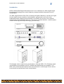
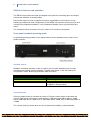
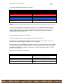
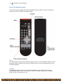
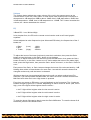
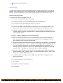
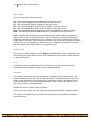
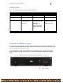
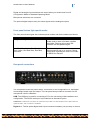
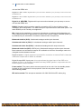
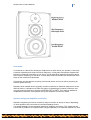
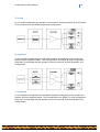
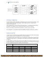
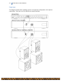
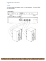
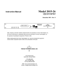
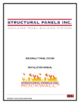
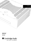
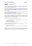
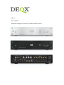
HDP-4 User's Manual Professional Digital Correction for Installers and End Users 2 DEQX HDP-4 Users Manual Copyright © 2012 DEQX Pty. Ltd. DEQX Calibrated is a trademark of DEQX Pty Ltd. All other product or brand names may be trademarks or registered trademarks of their respective owners. Disclaimer and Limitation of Liability DEQX Pty. Ltd. assumes no responsibility for loss or damage resulting from the use of its products. Please refer to the license supplied with the DEQX Calibration software. Warning To prevent fire or shock hazard, do not expose the unit to rain or moisture. To avoid electrical shock, do not open the unit. No user-serviceable parts are inside. Please refer any servicing to qualified personnel. Caution: Damage may result to your speaker drivers and other equipment if your audio system is connected incorrectly or if the unit is used incorrectly. Read this user manual in full before configuring your hardware and refer to your speaker manufacturer's specifications to ensure correct connection. If you are in doubt as to as the connection of your audio equipment please seek assistance from a professional audio installer or contact DEQX at [email protected]. The exclamation point within a triangle is intended to alert the user to the presence of important operating and maintenance instructions in the literature accompanying the product. The lightning with arrowhead symbol within a triangle is intended to alert the user to the presence of un-insulated “dangerous voltage” within the products’ enclosure that may be of sufficient magnitude to constitute a risk of electrical shock to person. DEQX HDP-4 Users Manual 3 Important Safety Instructions Read these instructions entirely before installing or operating this product. Keep these instructions. Heed all warnings. Follow all instructions. Do not use this product near water. Clean only with a dry cloth. Do not block any ventilation openings. Install in accordance with the manufacturer’s instructions. Do not install near any heat source such as radiators, heat registers, stoves, or other apparatus (including amplifiers) that produce heat. Do not defeat the safety purpose of the grounding-type safety plug. A grounding-type plug has two blades and a third grounding prong or blade. The third prong or blade is provided for your safety. If the provided plug does not fit into your outlet, consult an electrician for replacement of the obsolete outlet. Protect the power cord from being walked on or pinched, particularly at the plug and the point where the cord exits from this product. Do not use this product with a damaged cord or plug. Only use attachments and accessories specified by the manufacturer. When using rackmounting brackets, use only the brackets supplied or specified by the manufacturer. Unplug this product during lightning storms or when unused for long periods of time. Refer all servicing to qualified service personnel. Servicing is required when the product has been damaged in any way, such as when the power cord or plug are damaged, liquid has been spilled or objects have fallen into the product, the product has been exposed to rain or moisture, does not operate normally, or has been dropped. 4 DEQX HDP-4 Users Manual Cleaning and Maintenance Always unplug the product from the electrical outlet before cleaning. Do not use abrasive cleaners. Simply wipe the exterior with a clean soft cloth. A small amount of non-abrasive cleaner may be used on the cloth to remove any excessive dirt or fingerprints. Document Version Release date 1st June 2012. This document relates to version 3.0 of the DEQX Calibration Software and version 201.05 of the firmware. The colors of button lights when the PDC is used with earlier versions of the firmware may differ from those described herein. For the latest software, firmware and documentation check www.deqx.com Table of Contents Unpacking the unit 6 Accessories 6 About this manual 6 Introduction 7 DEQX unit features and operation 8 Front panel standard operating mode 8 Standby button 8 Volume Button 8 Profile selection buttons P1, P2 & P3 9 Use of the Remote Control 10 Mute 10 Standby 10 Volume 11 EQ 11 Advanced EQ 12 Input Select 14 Profile Select 14 User 14 Batteries 14 Factory Settings 15 Front panel IO configuration mode 15 Volume 16 P1 - Analogue input selection 16 P2 - Microphone selection 16 IO configuration notes 16 Front panel button light special modes 17 Rear panel connections 17 DEQX HDP-4 Users Manual 5 Installation 19 Determining speaker placement 19 Determining speaker configuration 19 Number of speakers 20 Number of drivers in each speaker 20 Crossovers 21 Speaker wiring and amplifier connection 21 Single-wired 22 Tri-wired 23 Bi-amplified 23 Choosing a configuration 24 Speaker connection 24 Single-amp 26 Bi-amp 27 Tri-amp 28 Glossary 29 Specification 30 Installation Information 31 Additional notes 32 Speaker room layout diagram 33 Connection diagram 34 Installation Warranty 35 Index 36 6 DEQX HDP-4 Users Manual Unpacking the unit Carefully remove the unit and the accessory kit from the shipping carton. Check visually for shipping damage. Contact both the shipper and DEQX immediately if the unit or any of the accessories bear any sign of damage from mishandling. All DEQX equipment is carefully inspected before leaving our factory. Keep the shipping carton and packing materials for future use or in the unlikely event that the product needs servicing. If the product is shipped without the original packaging, damage could occur and void the warranty . Accessories You should find the following in the accessory kit: One (1) AC mains cord One (1) USB cable One (1) microphone lead (Only with Calibration Kit) One (1) CD-ROM with the DEQX Calibration software One (1) measurement microphone, microphone holder (Only with Calibration kit) One (1) remote control Two (2) AAA batteries One (1) User’s manual and the Installer’s Manual are located on the DEQX CD. About this manual This manual is intended for both installers and users. The HDP-4, Express Mk2. For simplicity, in this manual both models are referred to as the DEQX unit. Please read this manual in full before installing or using the DEQX unit. Installers should also read the DEQX Calibration Installer’s Manual. The manual provides comprehensive details and operating instructions for all the features of the DEQX unit. Installers should record information specific to the Installation Information on page 31. Users should refer to Installation Information on page 31, for information specific to their installation, recorded by the installer. DEQX HDP-4 Users Manual 7 Introduction DEQX CalibratedTM-Digital EQualization and X-over Calibrated is a DSP (Digital Signal Processing) technology that corrects frequency response and time alignment errors in loudspeakers. The HDP (High Definition PDC) PDC (Professional Digital Calibration) units take the signal from the signal source, possibly via a preamplifier, and process it prior to the main amplification stage. Digital signal processing in the DEQX unit corrects for the specific characteristics of the speakers and room. The result is reduced distortion, coherent phase, a wider sound stage and improved imaging and accuracy. This diagram shows a typical home configuration, using the HDP-4. The CD player signal is preamplified, processed by the PDC, amplified and distributed to the speakers. The HDP-4 can provide dramatic performance improvements to a wide range of home stereo, home theatre and professional audio configurations. 8 DEQX HDP-4 Users Manual DEQX unit features and operation The DEQX unit provides a simple and elegant front panel for controlling input and output, volume and selection of stored profiles. Each profile stores one set of speaker correction, equalization and crossover curves. Setting up profiles and other configuration of the DEQX unit requires connecting a PC and running the configuration software. Your professional installer may have performed this setup. The rear panel offers connectors for input, output, PC connection and power Front panel standard operating mode In standard operating mode the front panel buttons control standby mode, volume, and profile selection. Standby button Disables or enables operation of the unit. When the unit exits standby mode, the last selected profile setting remains selected. Together with button 5, this also selects IO Configuration mode. Button light indicates state as follows: Button Light Green Yellow Red White SState On - Digital input On – Analogue input Standby Clipping – signal overloaded (analog input, or digital or analog output) Volume Button Press the upper button to increase the volume. Press the lower button to decrease the volume. Each press increments or decrements in 1dB steps from 0dB to above - 24dB, then in 2dB steps above -36dB, then in 3dB steps above -48dB, then in 6dB steps down to -120dB. The volume setting is saved when the unit is placed into standby or powered down. DEQX HDP-4 Users Manual 9 The button light indicates the gain as follows: Button Light Gain Off Red Yellow Green Blue Purple/Pink White From -120 dB to –60 dB From –60 dB to –50 dB From -50 dB to –40 dB From -40 dB to -30 dB From -30 dB to –20 dB From -20 dB to –10 dB From -10 dB to 0 dB The volume button light will flash when the unit is muted, except when the gain is below 60 dB. The unit can be muted with the software (ie with a PC connected) with either digital or analogue input selected. Furthermore, if digital input is selected but the unit does not detect a digital signal, as will usually happen if a CD player is paused, the unit will automatically go into mute mode . Profile selection buttons P1, P2 & P3 These three buttons select stored calibration profiles for operation. Pressing any two profile buttons together selects a fourth profile, typically set up as a bypass profile to pass signals through the unit unchanged. Users, please refer to Installation Information on page 31, to determine how your installer set up these three profiles. Installers, please record installation information in the space provided in Installation Information. Please refer to Factory Settingson page 15 for the profile default settings. Button lights indicate state as follows: Button Light All off State Unit is not in filtering mode. Refer to standby light to determine mode No filter profiles are loaded Bypass mode – Profile 0 selected Profile corresponding to this button is active All Yellow All lights white Only one button light white 10 DEQX HDP-4 Users Manual Use of the Remote Control The remote control supplied with the Express Mk2 and the HDP-4 controls a number of functions of the unit. Refer to the figure below. Mute The mute button mutes and unmutes the output of the unit. Press the Mute button to mute the output, press it again to turn mute off. When mute is on, the volume light on the unit front panel flashes. Standby The Standby button puts the unit in and out of standby, in the same manner as the Standby (I/0) button on the unit front panel. When in standby the light on the Standby button on the unit front panel is red. DEQX HDP-4 Users Manual 11 Volume The Volume button adjusts the output volume of the unit in the same manner as the volume button on the unit’s front panel. In other words, each button press increments or decrements in 1dB steps from 0dB to above -24dB, then in 2dB steps above -36dB, then in 3dB steps above - 48dB, then in 6dB steps down to -120dB. The ^ button increases the volume, the v button decreases the volume. EQ 3-Band EQ – Low, Mid and High In its simplest form, the EQ on the remote control can be used as a 3-band graphic equalizer. Unless adjusted to other frequencies (see Advanced EQ below), the frequencies of the 3 bands are § Bass § Mid: § Treble (Low): (High): 110Hz 440Hz 3500Hz To adjust the boost of the bass (low) band, press the Low button, then press the Gain+ button to boost the bass, or the Gain– button to cut the bass. Similarly, to adjust the boost of the mid band, press the Mid button, then press the Gain+ button to boost it, or the Gain– button to cut it. And to adjust the boost of the treble (high) band, press the High button, then press the Gain+ button to boost it, or the Gain– button to cut it. Each press of the Gain+ or Gain- buttons changes the boost of the relevant band by 1 dB. Holding down either of these buttons for more than 1 second will cause the boost to be changed continuously until the button is released. Whichever band you have selected will stay active until you select another band. For example, if you have pressed the Mid button, the Gain+ and Gain- buttons will affect the Mid band until either the Low or High button is pressed. Every time you press an EQ button, you get feedback on the front panel. The 3 rightmost buttons will light up green for 1 second. Depending on which control is 'active' (low, mid or high), one of the lights will be brighter than the others – § the P1 light will be brighter when the low control is active § the P2 light will be brighter when the mid control is active § the P3 light will be brighter when the high control is active To reset the boost of the active band, press the Gain 0dB button. To reset the boost of all the bands, press the EQ Reset button. 12 DEQX HDP-4 Users Manual Advanced EQ The EQ controls on the remote control allow the user to store and retrieve up to 100 EQ profiles, each consisting of up to three EQ settings. The EQ profiles are not the same as the four correction profiles (P1, P2, P3 and bypass) which can be stored on the unit. Outline of the EQ controls: There are 100 profiles, numbered 00 to 99 § There are 3 bands of EQ: bass, mid, treble § The bass and treble controls have adjustable gain and frequency § The mid control has adjustable gain, frequency and Q. § Q refers to the width of the EQ effect in octaves. Q can be 10 options from 1/12th octave to 4 octaves. Refer to the table of Q ‘quicksets’ on the remote control. § Frequency can be any value in the range 20 Hz to 24 kHz in semitone steps. You can also quickly jump from one frequency to another using the 'quicksets' as listed on the remote control. § Gain is +-12dB in 1dB steps. Using the EQ controls: § When you set the EQ controls, they are independent of the correction profiles, i.e. they remain like that for every correction profile (P1, P2, P3, Bypass). They will stay the same even if you turn off the power. § You can save the current EQ controls into an EQprofile, using SAVExx. For example, pressing ‘SAVExx’ then ‘5’ then ‘7’ saves the current EQ controls into EQprofile 57. You can load EQ controls from a previously saved EQprofile using EQxx. For example, pressing ‘EQxx’ then ‘0’ then ‘5’ loads EQprofile 05 into the current EQ controls. Note – two digits are required to save or load an Eqprofile § There is an 'active' EQ/tone control which is either bass, mid or treble. You select this by choosing "Low", "Mid" or "High". This controls what the Gain+, Gain-, Freq-, Freq+, Qx and Gain 0dB buttons do. § To reset the gain of a single control to 0dB, press Gain 0dB. This applies to the active tone control. § The default settings for the 3 bands are: § Low: 110Hz § Mid: 440Hz, 1 Octave bandwidth § High: 3500Hz DEQX HDP-4 Users Manual 13 The figure below shows the 3 tone controls in their default settings, each with 6 dB of boost. Also shown are the phase consequences of the default settings with 6 dB of boost. To reset all 3 tone controls to their defaults, use EQ Reset. This doesn't affect saved EQprofiles. Every time you do an EQ operation, you get feedback on the front panel. The 3 rightmost buttons will light up green for 1 second. Depending on which control is 'active' (low, mid or high), one of the lights will be brighter than the others – § the P1 light will be brighter when the low control is active § the P2 light will be brighter when the mid control is active § the P3 light will be brighter when the high control is active The DEQX unit has a total of 10 eq settings per correction profile. 3 of these are reserved for the remote control’s EQ controls and 7 are reserved for the parametric EQ accessible from the DEQX Cal software. There is an option to disable the remoteEQ and use 10bands of parametric EQ instead. If this option is turned on, then the EQ controls cannot be used. 14 DEQX HDP-4 Users Manual Input Select There are eight input selection buttons: A1 – this selects analogue RCA (unbalanced) as the input source A2 – this selects analogue XLR (balanced) as the input source D1 – this selects digital Toslink (Otpical) as the input source D2 – this selects digital BNC (also known as SPDIF) as the input source D3 – this selects digital RCA (also known as SPDIF) as the input source D2 – this selects digital XLR (balanced also known as AES/EBU) as the input source USB – this selects the optional USB Audio input. (if installed) as the input source Auto – this switches between the last selected analogue source and the last selected digital source. It will use the digital source if there is a signal received at the digital input, otherwise it will use the analog source. For example, if you were to press the An A1 or A2 button then the D2 button, then press the Auto button, the unit will use the digital D2 (BNC) signal if there is one, regardless of whether there is an analogue RCA signal or not, and use the analogue RCA signal if there is no digital D2 signal. Profile Select There are four profile selection buttons, Bypass, P1, P2 and P3. These correspond to the four profiles that can be stored on the unit and selected using the profile selection buttons on the unit front panel. User This button is for a user-defined function. This button is currently not functional. Its functionality will be available through a future software upgrade. Batteries The remote control takes two AAA size batteries, supplied with the remote control. The battery compartment is in the top of the remote control. To install the batteries, open the battery cover at the back of the remote control by sliding it upwards, as indicated by the arrow on the battery cover. Install the batteries with + and – signs matching the + and – signs of the figures in the compartment. Replace the cover by sliding it back into place. If the remote control does not work check that the batteries have been installed correctly. The charge of the batteries will run down over time and with use. Replace the batteries when this occurs DEQX HDP-4 Users Manual 15 Factory Settings The unit is shipped with the following factory settings: Profile L1, R1 (Sub) L2, R2 (Mid/Woofer) L3, R3 (Tweeter) Profile 0/ Bypass Bypass Bypass Bypass Profile 1 Bypass Bypass Bypass Profile 2 100Hz 24dB/Octave Linkwitz-Riley low pass filter 100Hz 24dB/Octave Linkwitz-Riley low pass filter 2000 Hz, 102 dB/Octave Linear Phase high pass filter 2000 Hz, 102 dB/Octave Linear Phase low pass filter Front panel IO configuration mode The front panel can operate in normal mode, described above, and IO configuration mode. To enter or exit IO Configuration mode, hold down the P3 button on the far right and press the 1/0 Standby button on the far left. In IO Configuration mode you can select rear panel digital inputs, rear panel analogue inputs, microphone mode, and digital sync source. Button lights indicate the selection made. 16 DEQX HDP-4 Users Manual Volume button -‐ Digital input selection Selects which rear panel digital input connector is in use. Button light Selection Off Green Blue No Selection Digital 4 Digital 3 P1 -‐ Analogue input selection Selects which rear panel analogue input connector is in use. Button light Selection Off Green Blue No Selection XLR RCA P2 -‐ Microphone selection Selects microphone input mode for calibration phase of installation. Button Light Off Red Green Blue White or Yellow Selection No Selection Microphone + Gain Microphone only Microphone + Gain + Phantom Power Microphone + Phantom Power IO configuration notes If using digital mode exclusively (analogue input set to No Selection), and there is no valid input source, the unit mutes. If digital and analogue modes are selected simultaneously, the unit uses the digital input if a valid digital source is detected, and if not defaults to analogue input. When the microphone input is selected, the unit is automatically placed in analogue mode. The unit defaults to the analogue condition when going from microphone to no-input DEQX HDP-4 Users Manual 17 Digital and analogue input selections are saved when you switch back from IO Configuration Mode to Standard Operating Mode. Microphone selections are not saved. The optional digital outputs carry the same signals as the analogue outputs. Front panel button light special modes The front panel button lights also indicate special modes and fault conditions as follows. Button Lights Selection All lights flashing blue Unit was booted in 'safe' mode - a special mode used in case a firmware upgrade has failed. Filtering will not work but firmware can be updated again. Red, Red, Red, Yellow, Red Red, Yellow, Red, Yellow, Red Red, Blue, Red Blue, Red, Blue Fault mode Unit has faulted and needs to be powered off and on to recover. Debug information regarding the fault can be sent to DEQX for analysis. Rear panel connections The rear panel houses the power switch, connectors for the configuration PC, and digital and analogue audio input and output. The rear panel also provides a connector for the microphone used in calibration. USB: The USB port is used for connecting a PC to the unit during initial installation and configuration. The RS232 serial port is provided as an alternative option. USB Audio: USB audio connector is used when the HDP-4 or HDP-Express II are fitted with the optional USB – I2S convertor is installed. Digital In 1: Toslink optical digital audio input connection between your pre-amp or source 18 DEQX HDP-4 Users Manual unit and the DEQX unit. Digital In 2: BNC S/PDIF digital audio input connection between your pre-amp or source unit and the DEQX unit. Digital In 3: RCA S/PDIF digital audio input connection between your pre-amp or source unit and the DEQX unit. Digital In 4: AES/EBU: Digital audio input connection between your pre-amp or source unit and the DEQX unit. RS232: Standard serial connector used for connecting a PC to the unit during initial installation and configuration. The USB serial port is provided as an alternative option. The lower RS232 port is currently not supported. Mic: Used during installation to connect a microphone to measure the loudspeaker and room response so that an appropriate correction filter can be created. Phantom power (on by default) may be selected for condenser measurement microphones. Balanced Audio In (XLR): 2 balanced analogue audio input channels. Unbalanced Audio In (RCA): 2 unbalanced analogue audio input channels Unbalanced Audio Out (RCA): 6 unbalanced analogue audio output channels Balanced Audio Out (XLR): HDP-4(only) 6 balanced analogue audio output channels. Both balanced and unbalanced outputs are available at all times. No settings need to be changed to select between the two. Digital outputs: 3 digital outputs are provided for connection to external DACs. Note that maxiumim sample-rate of 96kHz is available. Digital Output DSP input pass: this output allows the signal input of the DSP to be passed out with no processing to enalble multi way DEQX system in conjunsion with the RS232 system control interface. Power switch: The power switch removes power from the unit. Use the standby button located on the front panel for most purposes. Use the rear power switch when disconnecting cables. IEC mains socket: This accepts a standard 110-240V 50-60 Hz IEC mains plug. DEQX HDP-4 Users Manual 19 Installation End users should refer to their installer’s Installer Information on page 31 for details specific to their installation. Read below for more background information on how the DEQX system works. The hardware installation steps for professional installers are: § Determine the required speaker placement. See below. § Determine the required speaker configuration. See below. § Connect the components according to the chosen speaker configuration. Seeon page 24. The next phase of installation is software configuration. This involves setting up profiles for your configuration, room and primary listening position. The unit can produce output without software configuration, using the factory settings (See Factory Settings on page 15). However, the output will be optimized for your speakers or room only after software configuration has been successfully completed. Refer to the DEQX Calibration Software Manual for software configuration details Determining speaker placement Speaker placement within a room can have a dramatic effect on the overall sound quality. If DEQX's parametric equalizer has been used to reduce room effects, it is important to leave the room and speakers configured as they were when the room measurement was made. When you have determined the optimum speaker placement, record it in a diagram in the space provided in this manual under Speaker room layout diagram on page 33. Determining speaker configuration Configurations vary according to: § the number of speakers § the number of drivers in each speaker § the type of crossover in each speaker § speaker wiring - single wiring, bi-wiring or tri-wiring See the topics below for details. Depending on these factors, choose for each speaker a DEQX Speaker configuration according to the following table: 20 DEQX HDP-4 Users Manual Speaker Wiring Single-wired Bi-wored Bi-Amplified DEQX Speaker Configuration Single Amp Single Amp Bi-Amp Tri-wired Tri-Amplified Single Amp Tri Amp Single-wired Subwoofer Uses Speaker Internal Crossover YES YES Optional –depends on model YES Optional – depends on model Optional – depends on model Users DEQX Digital Crossover NO NO YES NO YES YES For example, if you have a stereo system consisting of two bi-amped speakers and a subwoofer, you would choose the Bi Amp DEQX speaker configuration for each of the biamped speakers and the Subwoofer configuration for the subwoofer. More details are given in the DEQX Installer’s Manual and online help. Number of speakers In this document the word speaker refers to loudspeaker cabinet. A stereo configuration has left and right speakers with optional subwoofer. A home theatre configuration usually has four or five loudspeakers plus one or two subwoofers. Number of drivers in each speaker In this document the word driver refers to an electro-mechanical speaker cone, dome, ribbon or horn unit within a speaker cabinet. For example, a speaker may contain a tweeter driver, a midrange driver and a woofer driver, with a crossover circuit that distributes low frequencies (bass) to the woofer, middle frequencies to the midrange driver, and high frequencies (treble) to the tweeter. DEQX HDP-4 Users Manual 21 Crossovers A crossover is a device for limiting the frequencies to each driver in a speaker. A two-way crossover operates at a single crossover frequency. A low-pass filter passes frequencies below the crossover frequency to one driver. A high-pass filter passes frequencies above the crossover frequency to the other. A three-way crossover divides the frequencies three ways at two crossover frequencies. Crossovers may be passive (requiring no external power source) or active (requiring an external power source). Speakers with multiple drivers typically contain crossovers to distribute frequencies to the internal drivers. A speaker may offer the option of bypassing the internal crossover and using an external crossover such as the DEQX PDC or HDP3. This requires additional amplification channels. See Speaker wiring and amplifier connection, below. Speaker wiring and amplifier connection Speakers containing more than one driver may be wired in a variety of ways, depending on how amplifiers are connected to individual speaker drivers. A bi-wired speaker has two separate cables for amplifier connection. The cables can be connected in parallel to a single amplifier (single-amplified) or a separate amplifier for each 22 DEQX HDP-4 Users Manual cable (bi-amplified). A tri-wired speaker has three separate cables for amplifier connection. The cables can be connected in parallel to a single amplifier (single-amplified) or a separate amplifier for each cable (tri-amplified). The diagrams below show a three driver speaker. Two driver speakers can also be singlewired, bi-wired and bi-amplified. Single-‐wired In a single-wired configuration, a single cable connects the amplifier to the speaker. An internal crossover within the speaker filters the signal to distribute the appropriate frequencies to each driver. This corresponds to the DEQX Single Amp configuration. Bi-‐wired In a bi-wired configuration the speaker is connected to a single amplifier by two cables. This corresponds to the DEQX Single Amp configuration. DEQX HDP-4 Users Manual 23 Tri-‐wired In a tri-wired configuration the speaker is connected to a single amplifier by three cables. This corresponds to the DEQX Single Amp configuration. Bi-‐amplified In a bi-amplified configuration two separate amplified channels are connected to the speaker by two separate cables. This corresponds to the DEQX Bi Amp configuration. Note that it is preferable that the speaker’s internal crossover be disconnected in this configuration. Tri-‐amplified In a tri-amplified configuration three separate amplified channels are connected to the speaker by three separate cables. This corresponds to the DEQX Tri Amp configuration. Note that it is preferable that the speaker’s internal crossover be disconnected in this configuration. 24 DEQX HDP-4 Users Manual Choosing a configuration Using individual amplifier channels for each driver results in improved sound quality. It also offers the opportunity to take advantage of DEQX digital crossovers, bypassing the speaker internal crossover. Some speakers offer a choice of wiring. By adding links to, or removing links from wiring terminals on the speaker you can choose single wiring, bi-wiring or tri-wiring. Refer to the speaker manufacturer's specification to ensure correct connection. For bi-amplified or tri-amplified configurations additional amplifier channels are required. Speaker connection A large variety of configurations are possible. Sample configurations shown demonstrating options available using a single DEQX unit, with stereo speakers. The illustrations below show single amp, bi amp and tri amp configurations using the RCA unbalanced audio outputs. For a description of the DEQX unit connectors see Rear panel on page 17. The table below shows the signal present at each DEQX unit rear panel connector in each possible configuration. Left channel outputs are numbered L1-L3 and right channel outputs R1- R3. Left and right inputs are named L and R respectively. Output Speaker Configuration Low L1 (left) Low R1 (right) Mid L2 (left) Mid R2 (right) High L3 (left) High R3 (right) Single Amp No connection No connection Left Speaker Right Speaker No connection No connection Bi-Amp No connection No connection Left Woofer Right Woofer Left Tweeter Right Tweeter Tri-Amp Left Woofer Right Woofer Left Mid-range Right Mid-range Left Tweeter Right Tweeter Subwoofer Left Sub Right Sub No connection No connection No connection No connection DEQX HDP-4 Users Manual 25 The table below lists the configurations and shows the connections for each channel. When using multiple DEQX units for home cinema applications these connections may not be the correct and the actual loudspeaker connected to a channel will depend on the installation. DEQX unit configuration Allocated Output “L” Channels L2 – Left Speaker “R” Channels R2 – Right Speaker L1 – Left Subwoofer R1 – Right Subwoofer Single Amp with Mono Subwoofer L2 – Left Speaker R2 – Right Speaker L1 – Left Subwoofer R1 – Same as L1 Bi Amp with Stereo Subwoofer L3 – Left Tweeter R3 – Right Tweeter L2 – Left Woofer R2 – Right Woofer L1 – Left Subwoofer R1 – Right Subwoofer L3 – Left Tweeter R3 – Right Tweeter L2 – Left Woofer R2 – Right Woofer L1 – Left Subwoofer L3 – Left Tweeter R1 – Same as L1 R3 – Right Tweeter L2 – Left Mid-range R2 – Right Mid-range L1 – Left Woofer R1 – Right Woofer Single Amp with Stereo Subwoofers Bi Amp with Mono Subwoofer Tri Amp When you have determined the optimum speaker connection and configuration, record it in a diagram in the space provided in this manual. See Installation Information, on page 31. 26 DEQX HDP-4 Users Manual Single-‐amp The diagram shows stereo speakers, each in a single-amp configuration, with optional subwoofers. This uses up to four DEQX unit output channels. DEQX HDP-4 Users Manual 27 Bi-‐amp The diagram shows stereo speakers, each in a bi-amp configuration, with optional subwoofers. This uses up to six DEQX unit output channels. 28 DEQX HDP-4 Users Manual Tri-‐amp The diagram shows stereo speakers, each in a tri-amp configuration. This uses six DEQX unit output channels. DEQX HDP-4 Users Manual 29 Glossary Bi-amp - a DEQX speaker configuration corresponding to a bi-wired speaker connected to two separate amplifier channels. Bi-amped speakers may have their internal passive crossovers by- passed. Bi-wired - A speaker configuration in which two cables connect the speaker to a single amplifier. Crossover -a device for limiting the frequencies to each driver in a speaker Crossover Frequency - the frequency at which a crossover operates Driver - One of the electro-mechanical cone (or ribbon) speakers located in a speaker cabinet HDP - (High Definition Processor) The DEQX CalibratedTM HDP-4 Processor is a 2-input, 6-output digital processor offering individual driver correction, high order digital crossovers, and room correction parametric equalisation. Single-amp -a DEQX speaker configuration corresponding to a single amplifier channel connected to a speaker in a single-wired, bi-wired or tri-wired configuration Single-wired - A speaker configuration in which a single cable connects the speaker to a single amplifier. Speaker -A loudspeaker cabinet containing one or more drivers Subwoofer - a DEQX speaker configuration corresponding to a subwoofer connected to a single amplifier channel Tri-amp - a DEQX speaker configuration corresponding to a tri-wired speaker connected to three separate amplifier channels. Tri-amped speakers may have their internal passive crossovers by-passed. Tri-wired - A speaker configuration in which the speaker is connected by three cables to a single amplifier. 30 DEQX HDP-4 Users Manual Specification Mains input voltage: 100-240VAC, 50-60Hz Power consumption: 60VA Dimensions: Height: 2U / 97mm Depth: 325mm Width: 430mm Signal to Noise Ratio: 107 dB, A-weighted Total Harmonic Distortion: 0.00045% Analogue input maximum levels: Balanced: +17 dBu differential (5.5 Vrms) Unbalanced: Default Level: +9 dBu (2.2 Vrms) Maximum Level: +13 dBu (3.5 Vrms) Analogue output maximum levels: Balanced: Default Level: +12 dBu differential (3.0 Vrms) Minimum Level: +8 dBu differential (2.0 Vrms) Maximum Level: +21 dBu differential (8.8 Vrms) Unbalanced: Default Level: +6 dBu (1.5 Vrms) Minimum Level: +2 dBu differential (1.0 Vrms) Maximum Level: +15 dBu (4.4 Vrms) Crossover slope (software selectable): up to 300dB/octave Latency: from 2.33ms depending on filter configuration A/D converter: 24-bit, 96kHz D/A converters: 32-bit, 192kHz Microphone: 48V bias Digital inputs: S/PDIF or AES/EBU or Optical PC connections: USB or RS232 Input Impedance (Balanced and Unbalanced): 50 kohms Output Impedance (Balanced): 150 ohms Output Impedance (Unbalanced): 75* ohms into an earth referenced amplifier i.e. one where the RCA GND pin connects to mains ground. This is normally the case. It is 75 ohms, plus 75 ohms in parallel with whatever the amplifier puts in series between its RCA connector and mains ground. If this is open then the impedance can be as high as 150 ohms (two pin power connector). Due to our policy of continuous product improvement the above specifications may change without notice. DEQX HDP-4 Users Manual 31 Installation Information Installer: Date: Serial Number: Profile 1: (Front panel button 3) Profile 2: (Front panel button 4) Profile 3: (Front panel button 5) Profile 4: (Any 2 front panel profile buttons) Single Amp/Bi Amp/Tri Amp/Subwoofer Single Amp/Bi Amp/Tri Amp/Subwoofer Single Amp/Bi Amp/Tri Amp/Subwoofer Single Amp/Bi Amp/Tri Amp/Subwoofer Single Amp/Bi Amp/Tri Amp/Subwoofer Speaker 1 configuration Speaker 2 configuration Speaker 3 configuration Speaker 4 configuration Speaker 5 configuration Speaker 6 configuration 32 DEQX HDP-4 Users Manual Additional notes DEQX HDP-4 Users Manual 33 Speaker room layout diagram (We suggest that you number speakers on this diagram to match corresponding entries in the Installation Information table above) 34 DEQX HDP-4 Users Manual Connection diagram DEQX HDP-4 Users Manual Installation Warranty 35 36 DEQX HDP-4 Users Manual Index Advanced EQ, 11, 12 AES/EBU, 14, 18, 30 Analogue input, 8, 16, 30 Bi-amp, 27, 29 Bi-amplified, 23 Bi-wired, 22, 29 Crossovers, 21 Digital input, 8, 16 IEC mains socket, 18 IO configuration, 15, 16 Microphone, 16, 17, 30 Profile, 9, 14, 15, 31 RS232, 17, 18, 30 Single-amp, 26, 29 Single-wired, 20, 22, 29 Speaker configuration, 19 Speaker connection, 24 Speaker placement, 19 Speaker wiring, 21 Specification, 30 Tri-amp, 28, 29 Tri-wired, 20, 23, 29 Volume, 8, 11, 16