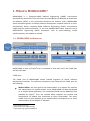
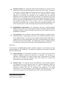
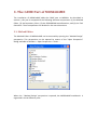
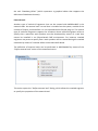
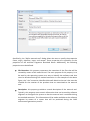
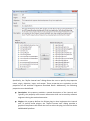
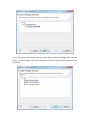
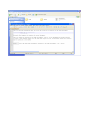
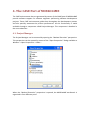
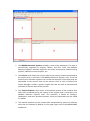
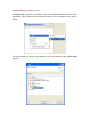
1
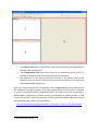
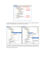
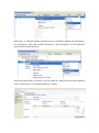
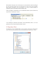
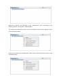
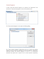
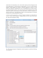
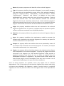
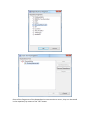
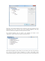
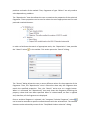
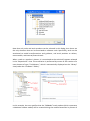
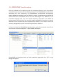
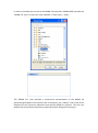
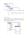
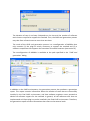
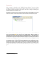
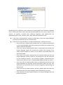
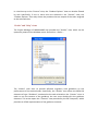
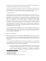
Introduction, Installation, and User Manual
Version 1.0
Contents
1. What is MOSKitt4ME? ............................................................................................................... 3
1.1. MOSKitt4ME Architecture .................................................................................................. 3
2. MOSKitt4ME Installation ........................................................................................................... 5
3. The CAME Part of MOSKitt4ME ................................................................................................ 7
3.1. Method Editor .................................................................................................................... 7
3.2. Repository Client .............................................................................................................. 14
3.3. SPEM2BPMN Transformation .......................................................................................... 34
3.4. Tool Generator ................................................................................................................. 37
4. The CASE Part of MOSKitt4ME ................................................................................................ 41
4.1. Project Manager ............................................................................................................... 41
Appendix A. Building the Eclipse plug-ins. .................................................................................. 51
1. What is MOSKitt4ME?
MOSKitt4ME is a Computer-Aided Method Engineering (CAME) environment
developed by researchers from the Centro de Investigación en Métodos de Producción
de Software (PROS) at the Universitat Politècnica de València (UPV). MOSKitt4ME
allows method engineers to define software development methods and also to semiautomatically obtain Computer-Aided Software Engineering (CASE) environments
supporting the method execution. To this end, MOSKitt4ME makes intensive use of
Model-Driven Engineering (MDE) techniques, such as meta-modeling, model
transformations, and models at runtime.
1.1. MOSKitt4ME Architecture
MOSKitt4ME is built on Eclipse1 and is composed of two main parts: the CAME part
and the CASE part.
CAME part
The CAME part of MOSKitt4ME allows method engineers to define software
development methods. The software components that comprise the CAME part are
the following:
Method Editor: the main goal of the method editor is to support the creation
and manipulation of method models. Since MOSKitt4ME has been developed
as an Eclipse-based application, this component builds on the Modeling Tools
provided by Eclipse2. Thus, the method editor supports the creation and
manipulation of models that instantiate an Ecore meta-model. The metamodel that has been defined in the method editor corresponds to an Ecore
representation of the SPEM 2.03 standard.
1
http://www.eclipse.org/
http://www.eclipse.org/modeling/
3
http://www.omg.org/spec/SPEM/2.0/
2
Repository Client: this component allows method engineers to connect to FTP
repositories containing method fragments that can be of two types: conceptual
or technical. Technical fragments encapsulate tools such as graphical editors
and model transformations. By means of the repository client, method
engineers can associate the elements of the methods with the technical
fragments that will support them during execution. The repository client also
allows users to create and store new technical fragments developed as Eclipse
plug-ins by means of MOSKitt4ME. On the other hand, conceptual fragments
are reusable method parts, such as tasks, roles, or work products. The
repository client allows user to create and store conceptual fragments, and
also to retrieve them in order to facilitate the construction of new methods.
SPEM2BPMN Transformation: this component provides a Model-to-Model
(M2M) transformation that automatically obtains executable representations
of SPEM 2.0 models. These executable representations are defined in terms of
the BPMN 2.0 standard4.
Tool Generator: this component allows method engineers to obtain Eclipsebased applications supporting the execution of the methods defined by means
of the Method Editor. The construction of these Eclipse-based applications is
supported by the Java Development Tools (JDT)5 and automated by the Plug-in
Development Environment (PDE)6. The applications that are produced by the
Tool Generator constitute the CASE part of the MOSKitt4ME architecture.
CASE part
The CASE part of MOSKitt4ME provides software support to the execution of the
methods defined in the CAME part. The software components that comprise the CASE
part are the following:
Project Manager: This component provides a set of Eclipse views that assist
software engineers during the execution of methods. The execution of
methods is automated by a process engine, which orchestrates the method
tasks and also invokes the software tools that enable the creation and
manipulation of the method products.
Software tools: The creation and the manipulation of the method products
are supported by a set of software tools (i.e., technical fragments, which are
represented in the figure above as Tool 1, Tool2, …, Tool n) that the Tool
Generator retrieves from the FTP repository and integrates in the CASE
environment. The Tool Generator only integrates the tools that are strictly
necessary to support the method defined by means of the Method Editor.
4
http://www.omg.org/spec/BPMN/2.0/
http://www.eclipse.org/jdt/
6
http://www.eclipse.org/pde/
5
2. MOSKitt4ME Installation
MOSKitt4ME has been conceived as an extension of the Eclipse-based MOSKitt tool7. In
order to install MOSKitt4ME in MOSKitt, the following steps must be performed:
Step 1. Download MOSKitt 1.3.10 from:
http://www.moskitt.org/eng/off/moskitt-descargas/.
The installation details of MOSKitt can be found at:
http://www.moskitt.org/eng/manuales/
Problems downloading MOSKitt? MOSKitt4ME also works on Eclipse, so an alternative
is to download Eclipse (Modeling Tools) Galileo and then proceed to Step 2.
Step 2. Install MOSKitt4ME from the following update site:
http://www.pros.upv.es/moskitt4me/Updates
To install MOSKitt4ME from this update site, open MOSKitt (or Eclipse) and select
“Install New Software…” from the “Help” menu. Then, push the “Add…” button to add
the MOSKitt4ME update site, and follow the wizard to install the tool. It is important to
activate the checkbox “Contact all update sites during install to find required software”
so that all the MOSKitt4ME dependencies can be resolved during the installation. One
of these dependencies is Graphiti (https://eclipse.org/graphiti/); it is important to add
the Graphiti update site (in the same way as the MOSKitt4ME update site) so that this
dependency can be resolved during the installation process. MOSKitt4ME has been
tested using Graphiti 0.7.3. The operating system was Windows 7.
7
http://www.moskitt.org/
3. The CAME Part of MOSKitt4ME
The installation of MOSKitt4ME adds the CAME part to MOSKitt. As described in
section 1, this part is composed of the following software components: (1) the Method
Editor, (2) the Repository Client, (3) the SPEM2BPMN transformation, and (4) the Tool
Generator. These components are detailed in the next subsections.
3.1. Method Editor
The Method Editor of MOSKitt4ME can be accessed by opening the “Method Design”
perspective. This perspective can be opened by means of the “Open Perspective”
dialog available at Window -> Open Perspective -> Other …
When the “Method Design” perspective is opened, the MOSKitt4ME workbench is
organized in three different parts:
1. The Library view offers a hierarchical view of the elements that compose the
method under construction.
2. The Configuration view only shows some of the method elements, that is, it
provides a mechanism for defining partial views on methods.
3. The properties of the method elements selected in the Library view can be
edited by means of specific editors that are opened by default on the right side
of the MOSKitt4ME workbench.
Both the Library view and the Configuration view of MOSKitt4ME are provided by the
EPF Composer. The EPF Composer is an open-source SPEM 2.0 editor that is provided
as part of the Eclipse Process Framework8 (EPF). This editor has been integrated in
MOSKitt4ME to support the creation and the manipulation of method models. In this
section, we provide a very brief summary of how methods are defined by means of the
EPF Composer. More details can be found at:
http://www.eclipse.org/epf/general/EPF_Installation_Tutorial_User_Manual.pdf
8
http://www.eclipse.org/epf/
EPF Composer
Defining software development methods by means of the EPF Composer comprises
two main steps:
Step 1.
Definition of the method content: the content of a SPEM 2.0 method is
primarily expressed using tasks, work products, and roles. Also, guidance can
be associated to these elements. The method content elements are generic,
that is, they do not take into account the particularities of specific processes.
Step 2.
Definition of processes: the generic method content is instantiated in
specific development processes. The main SPEM 2.0 process elements are
activities, which can be nested to define breakdown structures as well as
related to each other to define a flow of work. Activities contain references to
tasks (defined in step 1), which in turn reference their input/output work
products and their performing roles.
Method content and processes are defined within method libraries. Method libraries
can be created in MOSKitt4ME by means of the File menu: New -> Method Library. This
action opens the “New Method Library” wizard:
The “New Method Library” wizard allows the user to specify the destination path9 of
the method library and also the library description. Once the library is created, it can
be edited by means of the Library view.
9
The library path must not contain blanks.
The user can also open existing method libraries by means of the File menu: Open ->
Method Library, which opens the “Open Method Library” wizard:
When a method library is opened, it can be edited by means of the Library view. Note
that the Library view can only show one method library at a time.
In a method library, method content and processes are organized in hierarchical
structures named method plug-ins. Method plug-ins can be created by means of the
contextual menu of the Library view:
Method plug-ins contain content packages, which define method content, and process
packages, which define processes:
In content packages and process packages, new elements can be added and existing
elements can be deleted by means of the contextual menu:
The properties of the method content elements can be edited by means of form-based
editors that are opened by selecting “Edit” on the contextual menu (or double-clicking
the method content elements):
These form-based editors provide different tabs, which allow the user to edit different
types of properties. For instance, the “Roles” tab of the editor that is opened for tasks
(see image above) allows setting the performing roles of the tasks.
Unlike method content elements, processes are defined by means of a process editor,
which is also opened by selecting the “Edit” action (or double-clicking the process
elements):
By means of this editor, processes are defined as work breakdown structures. These
tree structures define activities, which contain references to method content elements
(i.e., taks, roles, and work products). Activities can be created by means of the
contextual menu:
References to method content elements can be created by adding task descriptors,
role descriptors, and work product descriptors. Task descriptors can be added by
means of the contextual menu:
Once a task descriptor is created, it can be linked to a specific task via the Properties
view -> General tab -> Link Method Element… button:
Work product descriptors and role descriptors are automatically created according to
the roles and work products that are associated to the task in the content packages.
Work product descriptors and role descriptors can also be created, deleted, or
modified by means of the Roles and Work Products tabs.
Finally, precedence relationships can be established between process elements by
means of the “Predecessors” column:
In this example, the “Business Logic Design” activity (identified by index = 1) is set as
predecessor of the “Data Persistence Design” activity.
3.2. Repository Client
The Repository Client of MOSKitt4ME can be accessed by opening the “Repositories”
view. This view can be opened by means of the Window menu: Show View -> Other …
The “Repositories” view allows method engineers to connect to FTP repositories that
store either technical method fragments or conceptual method fragments. Thus, the
functionality provided by the “Repositories” view is twofold. On the one hand, it allows
method engineers to associate technical fragments with elements of the method so as
to indicate the software tools that will support the method during its execution. On
the other hand, it allows method engineers to reuse method parts, which makes the
method construction process less error-prone, and more rapid and cost-effective.
In order to connect to a FTP repository, the Repositories view provides the “Add
Repository Location” action
, which can be found in the toolbar of the view. This
action opens the “Add Repository Location” dialog, which allows the user to enter the
host that contains the repository, the repository path, and his username/password:
When the connection with the FTP repository is established, a new repository location
is added to the Repositories view:
Repository locations are displayed in the “Repositories” view according to the
following pattern: user @ host : repositorypath.
The content of a repository location can be refreshed by means of the “Refresh” action
of the contextual menu.
Repository locations can be deleted by means of the “Discard location” action of the
contextual menu.
Technical Fragments
In order to add new technical fragments to a repository, the “Repositories” view
provides the “Create technical fragment” action of the contextual menu.
The “Create technical fragment” action opens the following dialog.
The “Create technical fragment” dialog allows the user to create new technical
fragments and also to specify their dependencies with other fragments. A dependency
relationship between two technical fragments, F1 and F2, is an unidirectional
association that implies that F1 requires F2 for its correct operation. Dependency
relationships form dependency trees, where nodes represent technical fragments and
all the descendants of a node represent its dependencies. Thus, the “Create technical
fragment” dialog supports the creation of technical fragments by means of a Tree
Viewer that represents a dependencies tree. This dependencies tree initially contains
one technical fragment (which is the root of the tree) and also allows the user to add
additional fragments representing its software dependencies. Additional fragments are
added by means of the “Add dependency” button, and existing fragments are deleted
by means of the “Remove dependency” button.
In order to edit the properties of a technical fragment selected in the dependencies
tree, the “Create technical fragment” dialog provides the “Edit” button, which opens
the “Edit technical fragment” dialog.
The “Edit technical fragment” dialog allows method engineers to specify the following
set of properties:
Name: this property represents the identifier of the technical fragment.
Type: this property classifies the technical fragment in one specific category.
The types that can be specified by means of the “Edit technical fragment”
dialog are “Graphical Editor”, “Meta-Model”, “Form-based Editor”, “Model
Transformation”, “Guidance”, and “Others”. In addition to these types,
MOSKitt4ME also supports two other types of technical fragments: “External
Tool” and “Internal Tool”. The main difference between the technical
fragments that can be created by means of the “Create technical fragment”
dialog and external/internal tools is that the latter do not encapsulate Eclipse
plug-ins. External and internal tools will be detailed at the end of this section.
Origin: this property establishes where the tool contained in the technical
fragment originates from. For instance, a software tool can represent a specific
software component extracted from the MOSKitt platform.
Objective: this property defines the goal that the technical fragment helps to
achieve.
Input: this property establishes the requirements needed to execute the
software tool contained in the technical fragment. For instance, the input of a
model transformation is its input model.
Output: this property defines the artifacts that can be produced by means of
the software tool contained in the technical fragment. For instance, the output
of a model transformation is its output model.
Plugins: this property defines the Eclipse plug-ins that implement the software
tool encapsulated in the technical fragment. To specify the plugins that will be
contained in the fragment, the “Edit technical fragment” dialog provides a
graphical component that allows the user to select the plug-ins from the
MOSKitt4ME workspace. In appendix A, we provide further details about how
these Eclipse plug-ins must be developed, since they have to meet a set of
requirements depending on the type of tool they implement.
Once all these properties are specified, errors may appear due to software
dependencies. That is, the plug-ins of the technical fragment may require other plugins that are not included in the fragment. In order to see the errors of a technical
fragment, the user can place the cursor over the fragment area in the dependencies
tree:
To solve the dependency errors, the user can add/remove technical fragments in the
dependencies tree by means of the “Add Dependency” and “Remove Dependency”
buttons. The “Add Dependency” button creates a new technical fragment and adds it
to the tree as a child of the fragment that is selected. Thus, the child fragment
represents a dependency of the parent fragment (i.e., the parent fragment requires
the use of the child fragment for its correct operation). On the other hand, the
“Remove button” allows the user to remove the fragment that is selected in the
dependencies tree and also all its nested fragments.
In addition, the user can establish dependencies between technical fragments by
means of the “Import” button. This button opens the “Import technical fragment”
dialog, which allows the user to import technical fragments from the repository. When
a fragment is imported, it is added to the dependencies tree as a child of the selected
fragment. Note that, unlike regular fragments, the icon of the imported fragments
contains a yellow arrow. This arrow represents that these fragments are references to
fragments that already exist in the repository.
Once all the fragments of the dependencies tree contain no errors, they can be stored
in the repository by means of the “OK” button.
Note that a new technical fragment will be created for each of the fragments of the
dependencies tree. This is not the case of the imported fragments, since they
represent references to fragments that were previously created.
The technical fragments that are stored in the repository are shown in the
“Repositories” view as childs of the repository location element:
Note that the fragments of type “Others” are not shown in this view. The reason for
this is that only the other types of fragments (i.e., editors, meta-models, model
transformations, guidance, external tools, and internal tools) can be associated to the
products and tasks of the method. Thus, fragments of type “Others” are only used to
solve dependency problems.
The “Repositories” view also allows the user to examine the properties of the technical
fragments. These properties can be used to select the most appropriate tool for each
particular method element:
In order to facilitate the search of appropriate tools, the “Repositories” view provides
the “Search” action
in the toolbar. This action opens the “Search” dialog:
The “Search” dialog allows the user to enter different values for the properties of the
fragments. Then, the “Repositories” view is filtered to show only the fragments that
match the specified properties. Thus, the “Search” action acts as a toggle button.
When it is activated, the “Repositories” view only shows the fragments matching the
property values that have been specified. When it is deactivated, no filter is applied
and, therefore, all the fragments are displayed.
Once a technical fragment is selected, the “Integrate Technical Fragment” action
can be used to associate a specific method element with the selected tool. The method
element can be selected by means of the “Task/Work Product selection” dialog:
Note that only tasks and work products can be selected in this dialog since these are
the only elements that can be associated to software tools. Specifically, tasks can be
associated to model transformations and guidance, and work products to editors,
meta-models, and external/internal tools.
When a task or a product is chosen, it is associated to the technical fragment selected
in the “Repositories” view. This association is performed by means of the creation of a
new element of type “Tool Mentor”, which is automatically displayed on the “Library”
view (under the “Guidance” folder):
In this example, the user specifies that the “DBModel” work product (which represents
a database schema model) will be created during the method execution by means of
the tool “Database_Editor” (which represents a graphical editor that supports the
definition of database schemas).
External tools
Another type of technical fragments that can be created with MOSKitt4ME is the
external tools. An external tool is a tool that is installed on the system, outside of the
context of Eclipse, and therefore it is not implemented as Eclipse plug-ins. This special
type of technical fragments support the situations where method engineers want to
specify that a particular work product must be developed by means of a tool that
cannot be installed in an Eclipse-based CASE environment. For instance, method
engineers may want to specify that a work product will be created during the method
execution by means of a textual editor such as Microsoft Word.
The definition of external tools can be performed in MOSKitt4ME by means of the
“Define external tool” action of the contextual menu.
This action opens the “Define external tool” dialog, which allows the method engineer
to specify the properties of the external tool:
Specifically, the “Define external tool” dialog allows the user to specify the properties
name, origin, objective, input, and output. These properties are equivalent to the
properties of the technical fragments described above. Additionally, the following
properties must be defined:
File Extension: this property represents the extension of the files that will be
created by means of the external tool. The main purpose of this property is to
be used by the operating system as a way to identify the software tool that
must be launched during the method execution. In the example of the above
figure, the “.doc” extension identifies Microsoft Word as the tool that must be
invoked for the creation of the products that are associated to the external
tool.
Description: this property provides a textual description of the external tool.
Typically, this property must contain information that can be used by software
engineers to configure the system so that the external tool is available during
the method execution. This information will be made available to the software
engineer by means of a report that will be produced during the CASE
environment generation process.
Internal tools
Another type of technical fragment are the internal tools. An internal tool is a tool that
is already installed in the CAME part of the MOSKitt4ME environment; for instance, a
specific component of MOSKitt such as the Transformation Manager or FEFEM, or an
Eclipse framework such as the Graphical Modeling Framework or the Java
Development Tools. Unlike external tools, these tools are implemented as Eclipse plugins. Nonetheless, since these tools are already installed, technical fragments
representing internal tools do not need to encapsulate the plug-ins but rather contain
references to them. One important advantage of internal tools is that they are not
subject to the same requirements as regular technical fragments (see appendix A).
Therefore, they can represent any type of software tool that can be conceived as
Eclipse plug-ins. The disadvange is that the Project Manager of MOSKitt4ME will not be
able to launch them automatically when the method is being executed.
The definition of internal tools can be performed in MOSKitt4ME by means of the
“Define internal tool” action of the contextual menu.
This action opens the “Define internal tool” dialog, which allows the method engineer
to specify the properties of the internal tool:
Specifically, the “Define internal tool” dialog allows the user to specify the properties
name, origin, objective, input, and output. These properties are equivalent to the
properties of the technical fragments described above. Additionally, the following
properties must be defined:
Description: this property provides a textual description of the internal tool.
Typically, this property must contain information that can be used by software
engineers during the method execution.
Plugins: this property defines the Eclipse plug-ins that implement the internal
tool. To specify these plugins, the “Define internal tool” dialog provides a
graphical component that allows the user to select the plug-ins from the whole
MOSKitt4ME platform.
Conceptual Fragments
In order to add new conceptual fragments to a repository, the “Repositories” view
provides the “Create conceptual fragment” action of the contextual menu.
The “Create conceptual fragment” action opens the following dialog.
The “Create conceptual fragment” dialog allows the user to create new conceptual
fragments. In order to do so, method engineers must specify the following set of
properties:
Name: this property represents the identifier of the conceptual fragment.
Type: this property classifies the conceptual fragment in one specific category.
The conceptual fragment types supported in MOSKitt4ME are “Task”, “Role”,
“Work Product”, “Content Element”, and “Process”. The first three types of
fragments contain respectively tasks, roles, and work products. Conceptual
fragments of type “Content Element” can contain any combination of these
elements; for instance, a task and its associated input/output products. Finally,
fragments of type “Process” contain reusable processes, which are represented
in SPEM 2.0 by means of the primitive “Capability pattern”.
Origin: this property establishes where the method element contained in the
conceptual fragment originates from. For instance, a conceptual fragment can
contain a task extracted from the gvMetrica method10.
Objective: this property defines the purpose of the element contained in the
conceptual fragment.
Content: this property defines the method elements encapsulated in the
conceptual fragment. To specify the elements contained in the fragment, the
“Create conceptual fragment” dialog provides a graphical component that
allows the user to select the elements from the Method Library that is opened
in the Method Editor. This graphical component only shows the elements that
can be contained in the fragment according to the type of fragment that is
selected. For instance, if the type of fragment that is selected is “Task”, then
the graphical component only shows the tasks defined in the Method Library.
In a similar way to technical fragments, the conceptual fragments that are created by
means of the “Repositories” view are shown as children of the repository location.
10
http://www.gvpontis.gva.es/fileadmin/conselleria/images/Documentacion/migracionSwAbierto/gvMET
RICA/introduccion/gvMetrica_Introduccion.htm
Also, the “Repositories” view allows method engineers to examine the fragment
properties. These properties can be used to select the most appropriate method
element for the method under construction.
Once a conceptual fragment is selected, the “Integrate conceptual fragment” action
can be used to integrate the selected fragment into the method under construction.
The integration of a conceptual fragment is performed in two different ways
depending on the type of fragment being integrated. The integration of conceptual
fragments of type “Task”, “Role”, “Work Product”, and “Content Element” is
performed by means of the “Content Package Selection” dialog.
The “Content Package Selection” dialog allows users to select the content package
where the tasks, roles, and work products will be stored.
The conceptual fragments of type “Process” are integrated by means of the “Process
fragment integration” wizard. This wizard takes the user through three steps. First, the
user must select an element of a method process. The element that is selected will be
the destination of the process encapsulated in the process fragment.
The integration of the process fragment can be performed in two different ways:
“Extend” and “Copy”. If “Extend” is selected, the process fragment will not be included
in the process but rather copied separately and referenced. If “Copy” is selected, all
the content of the process fragment will be copied into the selected process element.
In the second step of the wizard, the user must select the process package where the
process contained in the process fragment will be stored. If the process already exists
in the package, the process will not be copied. In this case, the third step of the wizard
is omitted.
In the third step of the wizard, the user must select a content package of the method
library. In this package, the content elements referenced by the process fragment will
be stored.
3.3. SPEM2BPMN Transformation
Once the method and its supporting tools are completely defined, users must obtain
executable representations of the method processes. The SPEM2BPMN transformation
automates this task. Specifically, the SPEM2BPMN transformation automatically
obtains BPMN 2.0 processes from the SPEM 2.0 model. Complementing the SPEM 2.0
method definition with BPMN 2.0 has two main advantages. First, BPMN 2.0 is an
executable language and, thus, the method becomes executable by a BPMN 2.0
process engine. Second, users can manually modify the BPMN 2.0 processes to specify
workflows more complex than those supported by SPEM 2.0. For instance, users can
manually add gateways, which cannot be represented in SPEM 2.0.
In order to invoke the SPEM2BPMN transformation, open the contextual menu of the
root element and select Diagrams -> Open BPMN 2.0 Diagram.
If the BPMN 2.0 processes have not been previously generated, click “OK” on the
dialog that appears:
This action generates a BPMN 2.0 process for each SPEM 2.0 activity. For instance, the
BPMN 2.0 process generated for the “Data Persistence Design” activity is the following:
Note that each BPMN 2.0 task corresponds to a SPEM 2.0 task. In addition, BPMN 2.0
call activities are created to connect all the processes that are generated.
The Activiti Designer11 is the editor that has been integrated in MOSKitt4ME to support
BPMN 2.0. By means of this editor, method engineers can manually modify the
generated processes. For instance, they can add BPMN 2.0 gateways to enhance the
process workflows.
In addition to the “Open BPMN 2.0 Diagram” action, MOSKitt4ME also provides the
“Delete BPMN 2.0 Diagram” action, which deletes the generated BPMN 2.0 processes:
11
http://www.activiti.org/
In order to facilitate the access to the BPMN 2.0 processes, MOSKitt4ME provides the
“BPMN 2.0” view. To open this view: Window -> Show View -> Other …
The “BPMN 2.0” view provides a hierarchical representation of the BPMN 2.0
processes generated for the process that is selected in the “Library” view. Each of the
elements of the hierarchy represents one specific BPMN 2.0 process. The user can
double-click any of these processes to open the Activiti Designer file storing it.
3.4. Tool Generator
Once the executable representation of the method is obtained, the Tool Generator of
MOSKitt4ME automates the construction of a supporting CASE environment. The Tool
Generator can be invoked by opening the contextual menu of the “Library” view and
selecting the “Generate CASE Tool” action.
This action opens the “CASE tool generation” dialog, which allows the user to enter the
destination path and the name of the CASE tool.
The CASE tool generation process automatically performs two main steps:
Step 1.
The Eclipse plug-ins contained in the technical fragments associated to
the method elements are downloaded from the FTP repository and imported
into the workspace (if they are not already imported).
Step 2.
An Eclipse Product Export process12 is launched. This process produces
the final Eclipse-based CASE environment. Once this tool is produced, the plugins that were imported into the workspace in step 1 are deleted so that the
workspace returns to its original state.
12
http://help.eclipse.org/galileo/index.jsp?topic=/org.eclipse.pde.doc.user/guide/tools/export_wizards/
export_product.htm
The duration of step 1 and step 2 depends on the size and the number of software
tools that are required to support the method. Thus, the CASE tool generation process
may take from a few minutes to more than one hour.
The result of the CASE tool generation process is a reconfiguration of MOSKitt that
only contains (1) the plug-ins strictly necessary to support the method and (2) a
software component that supports the execution of method instances (see section 4).
The reconfiguration of MOSKitt is available at the path specified in the “CASE tool
generation” dialog.
In addition to the CASE environment, the generation process also produces a generation
report. This report contains information about the number of tools that are successfully
installed in the final CASE environment, and how software engineers must proceed to
obtain full software support for the method. In general, all the software tools that are
implemented as Eclipse plug-ins can be installed in the final CASE environment. Therefore,
the generation report contains information that refers to the external tools.
4. The CASE Part of MOSKitt4ME
The CASE environments that are generated by means of the CAME part of MOSKitt4ME
provide software support for software engineers performing software development
projects. These CASE environments guide them throughout the development process
and also partially automate the process performance. All this functionality is made
available through a component called Project Manager. This component is detailed in
the next subsection.
4.1. Project Manager
The Project Manager can be accessed by opening the “Method Execution” perspective.
This perspective can be opened by means of the “Open Perspective” dialog available at
Window -> Open Perspective -> Other …
When the “Method Execution” perspective is opened, the MOSKitt4ME workbench is
organized in four different parts:
1. The MOSKitt Resource Explorer provides a view of the workspace. This view is
hierarchically organized in projects, folders, and files. From the MOSKitt
Resource Explorer, software engineers can create new projects, delete existing
projects, add files to these projects, etc.
2. The Process view shows the current state of the process instance associated to
the project that is selected in the MOSKitt Resource Explorer view. From the
Process view, software engineers can invoke the execution of the tasks that are
executable at the current state of the process. Once a task is finished, the
Project Manager invokes a process engine that sets the task as executed and
proceeds to the next state of the process.
3. The Product Explorer view shows a hierarchical picture of the artifacts that
have been produced during the course of the project that is selected in the
MOSKitt Resource Explorer view. This hierarchy is based on domains,
subdomains, and work product elements, which are obtained from the SPEM
2.0 model.
4. The method products can be created and manipulated by means of software
tools that are opened by default on the upper-right side of the MOSKitt4ME
workbench.
MOSKitt Resource Explorer view
In MOSKitt4ME, projects are created by means of the MOSKitt Resource Explorer view.
Specifically, new projects can be created by means of the contextual menu: New ->
Other …
This action opens the "New" wizard, where the user must select the type "MOSKitt4ME
Project".
Then, on the next page of the wizard, enter the project name and select the process to
be associated to the project. This page allows the user to choose among all the
processes that are defined in the method library.
When the wizard is finished, a new MOSKitt4ME project is added to the MOSKitt
Resource Explorer view.
Process view
When a project is selected on the “MOSKitt Resource Explorer” view, the Project
Manager automatically invokes the Activiti Engine13, which returns the current state of
the process instance associated to the project. The view in charge of showing this
process instance is the “Process” view.
By default, the Process view only shows those tasks that are executable at the current
state of the process. These tasks (and their parent activities) are displayed in green.
To see all the activities and tasks of the process, users can make use of the “All Tasks”
action of the toolbar
. This action acts as a toggle button. When the button is
deactivated, the Process view only displays the executable tasks (i.e., the tasks that can
be performed in the current state of the process). When it is activated, all the tasks of
the process are displayed. In this case, non-executable tasks are displayed in red,
executable tasks are displayed in green, and the tasks that have already been executed
are displayed in blue. The color of the activities depends on their nested tasks and subactivities. An activity is shown in blue if and only if all its tasks and sub-activities have
already been executed. On the other hand, the activity is shown in red if and only if all
its tasks and sub-activities are non-executable. Otherwise, the activity is shown in
green.
13
http://www.activiti.org/
Displaying tasks in different colors represents a useful guidance for software engineers
since it tells them which tasks must be executed based on the current state of the
project. To execute a specific task, software engineers must double-click the
(executable) task in the “Process” view. Then, different possibilities exist:
If the task is associated to a model transformation, then the Project Manager
launches the execution of the transformation.
If the task is not associated to a model transformation, there are six cases:
o If the task has an output work product that has an editor associated to
it, the Project Manager opens the wizard that enables the creation of an
empty model for that editor.
o If the task has an output product with an associated meta-model, the
Project Manager opens the wizard that enables the creation of an
empty model editable by means of the default tree-based editor for
that meta-model.
o If the task has an output product with an associated external tool, the
Project Manager creates a new file. The extension of the file name will
be the extension stored in the technical fragment representing the
external tool. Once the file is created, MOSKitt4ME attempts to open it.
o If the task has an output product with an associated internal tool, the
Project Manager just provides textual information about the tool. This
information is retrieved from the technical fragment representing the
internal tool.
o If the task has an output product, but this product does not have any
associated tool, the Project Manager does not perform any action.
o If the task does not have output products, the Project Manager does not
perform any action.
When the execution of a task has been requested and the output products are already
created, subsequent execution requests for the same task do not have the same
effect. Specifically, when the user double-clicks an executable task that has already
been started, the Project Manager opens its output products so that the user can
modify them.
Once a task is considered finished, the user must manually set the task as executed.
This can be performed by means of the “Run” action of the toolbar
. When a task is
set as executed, the Project Manager automatically notifies the Activiti Engine, which
takes the process instance to its next state.
In addition to the “Run” action, the Process view also provides the “Run Repeatable”
action . This action is only enabled for tasks that were set as “repeatable” during the
method definition. When the “Run Repeatable” action is invoked for a task, then the
task is considered again as not started. This means that subsequent execution requests
will have again the same effect as if the task had never been executed.
The “Process” view also provides support to task filtering based on the role performed
by the user. To select a specific role, users can make use of the “Role Selection” action
of the toolbar . Similarly to the “All Tasks” action, this action acts as a toggle button.
When the button is deactivated, tasks are not filtered. When it is activated, tasks are
filtered based on the selected roles. The role selection is performed by means of the
“Role Selection” dialog:
For instance, if the “Analyst” role is selected, the Process view only shows the tasks
performed by this role (note that the toolbar always shows the roles that are selected).
The Process view also provides support to returning to previous states of the process
by means of the “Undo” action of the toolbar
. This action allows the user to go
back in the process execution but does not delete the files that have already been
created.
Product Explorer view
When a project is selected on the “MOSKitt Resource Explorer” view, the “Product
Explorer” view shows a hierarchical representation of the method products that have
been created for the project. This hierarchy is based on the elements of type “Domain”
and “Work Product” defined in the SPEM 2.0 method model. In SPEM 2.0, domains are
defined as hierarchies grouping related work products. Domains can be further divided
into sub-domains, with work product elements at the leaf-level of this hierarchy. Based
on this idea, the “Product Explorer” view shows the domains defined in the method
and the sub-domains and work products contained in these domains. Also, the
“Product Explorer” shows the files that represent each particular work product.
In a similar way to the “Process” view, the “Product Explorer” view can also be filtered
by role. Specifically, if one or more roles are selected in the “Process” view, the
“Product Explorer” view only shows the products that are output of the tasks assigned
to the selected roles.
“Guides” and “Help” views
The Project Manager of MOSKitt4ME also provides the “Guides” view, which can be
opened by means of the Window menu: Show View -> Other ...
The “Guides” view aims to provide software engineers with guidelines on the
performance of the method tasks. Specifically, the “Guides” view shows the SPEM 2.0
elements of type “Guidance” associated to the task selected on the “Process” view. In
order to see the content of the guidance, the user must double-click the guidance
elements. This action opens the “Content” view provided by the EPF Composer, which
provides an HTML representation of the guidance contents:
As another type of guidelines, the Project Manager also provides support to the Eclipse
dynamic context help, which is shown in the “Help” view provided by Eclipse.
Specifically, when a task is selected in the “Process” view, the Project Manager obtains
the technical fragments of type “Guidance” that are associated to this task. Then, the
guidelines contained in these fragments are displayed in the “Help” view.
Appendix A. Building the Eclipse plug-ins.
MOSKitt4ME is an Eclipse-based CAME environment that supports the development of
Eclipse plug-ins that can be encapsulated as reusable software assets (i.e., the
technical fragments). Then, these assets can be reused during the definition of
methods and the construction of the supporting CASE environments.
In general, eclipse plug-ins can implement different types of tools, such as graphical
editors, form-based editors, or model transformations. For each of these types of
tools, MOSKitt4ME provides different Eclipse-based technologies that facilitate the
development of the plug-ins.
The plug-ins that are developed with MOSKitt4ME must meet a set of requirements so
that they are compatible with the Project Manager (i.e., the Project Manager can
automatically invoke the tools that the plug-ins implement). In the following, we
describe for each type of tool the Eclipse technologies that can be used for their
development and also the requirements that the tools must meet.
Meta-Models
Meta-Models can be specified in MOSKitt4ME by means of the Ecore language, which
is provided as part of the Eclipse Modeling Framework (EMF14). EMF supports the
definition of meta-models, and also provides generation facilities to obtain (1) the set
of Java classes implementing the meta-model, along with (2) a set of classes that
enable editing of the models, and also (3) a basic tree editor.
In order to be compatible with the MOSKitt4ME requirements, the plug-ins contained
in a technical fragment of type “Meta-Model” must define an Ecore meta-model. In
addition, the Java classes, the editing classes, and the tree editor must have been
generated.
Graphical Editors
Graphical Editors can be developed in MOSKitt4ME by means of the Eclipse Graphical
Modeling Framework (GMF15). GMF is framework that is built on EMF and applies a
model-driven approach to obtain fully-functional graphical editors. Specifically, GMF is
based on the specification of a set of models that define (1) an Ecore meta-model, (2)
the graphical elements to display in the editor, and (3) the tools that will appear in the
palette, menus, and toolbars. Once these models are defined, a set of generative tools
14
15
http://www.eclipse.org/modeling/emf/
http://www.eclipse.org/modeling/gmp/
automatically obtain a graphical editor supporting the construction of models that are
compliant with the Ecore meta-model that has been specified.
There are no particular requirements to be met by the plug-ins contained in the
technical fragments of type “Graphical Editor”. All graphical editors developed by
means of GMF are compatible with the Project Manager of MOSKitt4ME.
Form-based Editors
Form-based Editors can be developed in MOSKitt4ME by means of Fefem16. Fefem is a
development framework that facilitates the construction of form-based editors by
implementing a set of patterns that are typically found when developing this kind of
editors (e.g., the need to show in a Textbox the value of a property of type String).
Thus, the development of Form-based editors is reduced to simple pattern
composition. Fefem is based on the use of the SWT17 and JFace18 libraries, which are
two libraries of graphical components that are provided by the Eclipse community.
Form-based editors can directly be built by means of these libraries. However, we
recommend the use of Fefem since it significantly reduces the workload inherent to
the development of this kind of tools.
There are no particular requirements to be met by the plug-ins contained in the
technical fragments of type “Form-based Editor”. All form-based editors developed by
means of Fefem (or directly by means of SWT and JFace) are compatible with the
Project Manager of MOSKitt4ME.
Model Transformations
Model transformations can be developed in MOSKitt4ME by means of the ATL 19 and
Xpand20 languages, which are two programming languages especially designed by the
Eclipse community to implement Model-to-Model and Model-to-Text transformations
respectively.
To be compatible with MOSKitt4ME, the model transformations can be implemented
in any language. Nonetheless, the plug-ins contained in a technical fragment of type
“Model Transformation” must meet two requirements:
1. The model transformation must be declared by means of the extension point
“es.cv.gvcase.trmanager.transformation”. This extension point is provided by
the Transformation Manager of MOSKitt. The MOSKitt Transformation
Manager is a software component that provides a set of Java classes for the
16
http://www.moskitt.org/eng/fefem-creacion_de_formularios/
http://www.eclipse.org/swt/
18
http://wiki.eclipse.org/JFace
19
http://www.eclipse.org/atl/
20
http://www.eclipse.org/modeling/m2t/?project=xpand
17
specification and invocation of model transformations, and also implements a
graphical user interface to make these transformations available in the MOSKitt
workbench.
2. In the declaration of the transformation by means of the extension point, the
user must provide a Java class extending the class “Transformation” of the plugin “es.cv.gvcase.trmanager”. This class is an abstract class that declares two
abstract methods: “transform” and “inputsValid”. The first method must
implement the invocation of the transformation. The second method must
implement validation rules for the input model of the transformation.
Guidance
Contextual help can be developed in MOSKitt4ME by means of the HTML and XML
languages21. In order for this help to be compatible with MOSKitt4ME, the Eclipse plugin(s) that implement the help must make use of two extension points:
1. The “org.eclipse.epf.authoring.ui.helpcontextprovider” extension point must be
used to declare a help context identifier. This context identifier will be passed
to the Eclipse “Help” view when the task associated to the “Guidance”
fragment is selected in the MOSKitt4ME “Process” view.
2. The “org.eclipse.help.contexts” extension point must be used to declare a
“contexts.xml” file. This file associates the help context identifier with the
HTML files implementing the help.
21
http://help.eclipse.org/juno/index.jsp?topic=%2Forg.eclipse.platform.doc.isv%2Fguide%2Fua_help_con
text.htm